Delta 36-075 User manual

l0" Compound
Power
Miter
Saw
(Model
36-075)
2
a
{
F
C
o
{
o
z
=
z
c
r
t,'t
PARTNO.1349819
ODelta
Internationall\,4achineryCorp.1998
A
AA trIELTA

TABLEOFCONTENTS
SAFETY
RULES.
ADDITIONALSAFETYRULES
FORCOMPOUND
MITERSAWS. ........4
UNPACKING
ASSEMBLYINSTRUCTIONS. .....5
AssemblingTable
LockHandle .....5
RotatingTableTogO
Degree
Position ......5
MovingCuttinghead
ToTheUp
Position ....6
Assembling
Dust
Bag .......6
FASTENING
MACHINETOSUPPORTING
SURFACE .....6
CONNECTING
SAW
TOPOWERSOURCE
PowerConnections..... -...7
MotorSpecifications... -----7
Grounding
Instructions -----.7
EXTENSTONCORDS ......8
OPERATING
CONTROLS
AND
ADJUSTMENTS
StartingAnd
Stopping
Machine .-...8
LockingSwitch
lnThe"OFF"
Position .... .8
RotatingTableForMiterGutting.... """9
PointerAndScale ....9
AdjustingPointer ....9
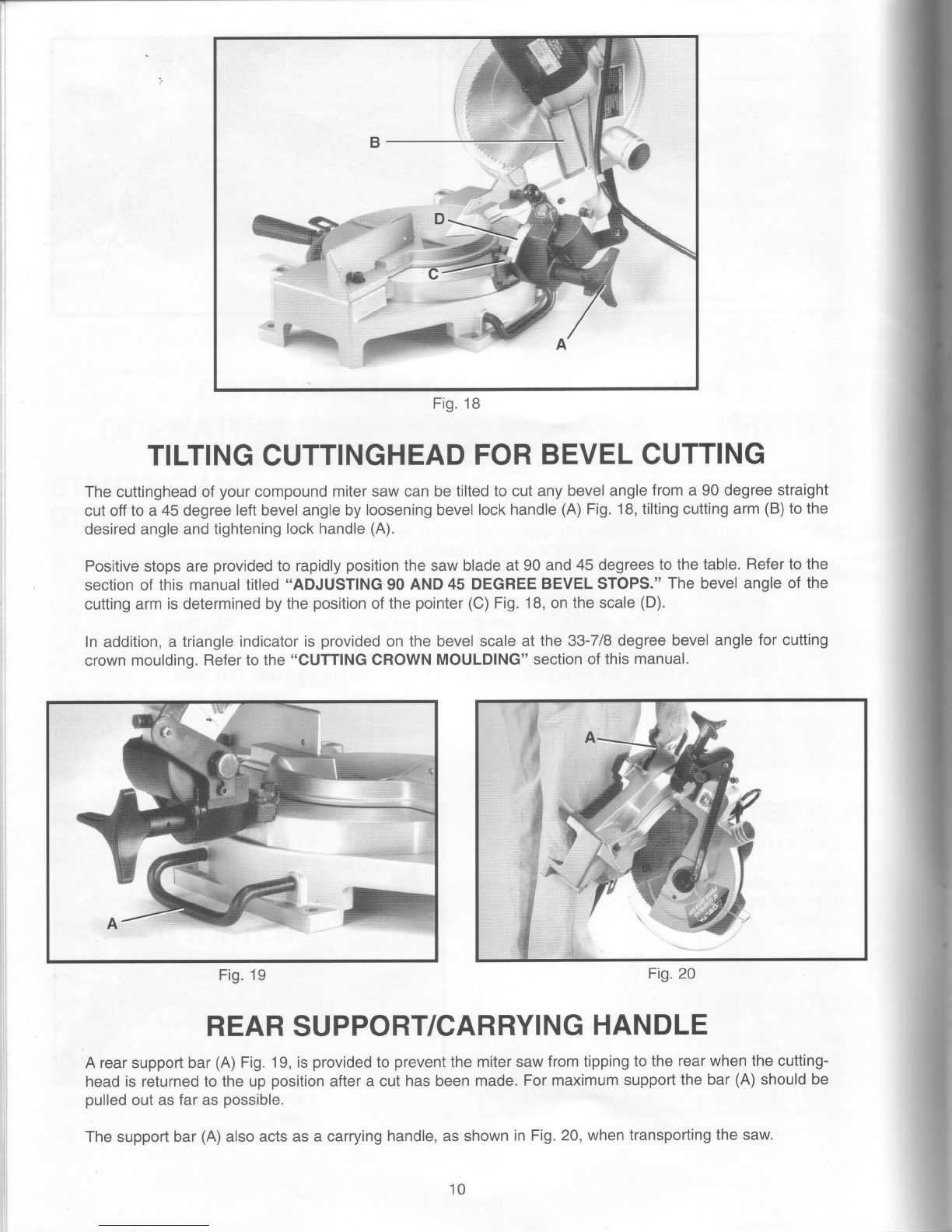
TiltingCuttinghead
ForBevelCutting .....10
RearSupporVCarrying
Handle .....10
Adjusting
BladeParallel
ToTableSlot.. ... 11
Adjusting
Fence90
Degrees
ToBlade . ....11
Adiusting
DownwardTravel
OlSaw
Blade. .......11
Adjusting
90And
45Degree
BevelStops
.... ---.12
AdjustingTension
OfCuttinghead
ReturnSpring '.. -.. -.12
LockingCuttinghead
lnTheDown
Position ......13
TYPICALOPERATIONSAND
HELPFULHINTS. ........13
AuxiliaryWood
Fence. .--. -14
GeneralCutting
Operations .......14
CuttingAluminum ...15
Cutting
BowedMaterial ....15
Gutting
Crown
Moulding. ...16
MAINTENANCE
ChangingThe
Blade .----- -17
BrushInspectionAnd
Replacement. -'....18
rArtrlELTA
Delta
Building
Tradesand
HomeShop
Machinery
Two
YearLimited
Warranty
Deltawill repairor replace,at its expenseand at its option, any Deltamachine,
machinepart,or machineacces-
sory which in normai use has proven to be delective in workmanship or material,
provided that the customer
returnsthe product prepaid
to a Delta
factory servicecenteror authorized
servicestationwith proof of purchase
ol the product withih two years and provides Delta
with reasonable
opportunity to verify the allegeddefect by
inspeciion.Deltamay requirethat electric motors be returnedprepaid
to a motor manufacturer's
authorized
sta-
tion for inspeclion and repair or replacement.
Deltawill not be responsiblefor any asserteddefect which has
resulted
from normalwear,misuse,
abuseor repairor alteration
madeor specifically
authorized
by anyoneother
than an authorizedDeltaService
facility or representative.Under no circumstanceswill Deltabe liablefor inci-
dental or consequentialdamagesresulling from defectiveproducts,This warranty is Delta'ssole warranty and
sets forth the customer's exclusive remedy,
with respectto defectiveproducts; all other warranties,
express or
implied,
whetherof merchantability,
fitness for purpose,or otherwise,
areexpresslydisclaimedby Delta.

SAFETYRULES
Woodworking
can be dangerousif safeandproper
operating
procedures
arenotfollowed.
As withall machinery
therearecertain
hazards
invOlved
withthe
operation
ofthe
product.
Usingthemachinewith
respectandcautionwill
considerablylessen
the
possi-
bilityof personal
injury.However,
if normal
safety
precautions
areoverlookedor ignored,
personal
injurytotheoperatormayresult.
Safetyequipment
such
as
guards,push
sticks,hold-downs,
featherboards,
goggles,
dust
masks
andhearing
protection
canreduce
your
potential
for
injury.But
eventhe
best
guard
won't
make
up
for
poor
judgment,
carelessnessorinattention.
Always
usecommon
sense
andexercise
cautionintheworkshop.
lfa procedure
feels
dangerous,
don'ttryit.Figureoutanalternative
procedure
thatfeels
safer.REMEMBER:
Your
personal
safetyis
your
responsibility.
Thismachine
was
designedfor
certainapplications
only.DeltaMachinery
stronglyrecommends
thatthismachine
not
bemodified
and/oj
yse! ]or anyapplication
otherthanthatforwhichit wasdesigned.lf you haveanyquestions
relative
to a particular
applica-
tion,DONOT
usethemachine
until
you
havefirst
contacted
Deltatodetermineifit
canorshouldbe
performed
onthe
product.
DELTA
INTERNATIONAL
MACHINERY
CORP.
MANAGER
OFTECHNICAL
SERVICES
246ALPHA
DRIVE
PITTSBURGH,
PENNSYLVANIA
1
5238
(lN
CANADA:
644IMPERIAL
ROAD,
GUELPH,ONTARION1H6M7)
WARNING:
FAILURE
TO
FOLLOW
THESE
RULES
MAY
RESULT
IN
SERIOUSPERSONAL
INJURY
1.FOR
YOUR
OWNSAFETY,
READINSTRUCTION
MANUAL
BEFORE
OPERATINGTHE
TOOL.Learn
the
tool's
application
and limitations
as wellas the specific
hazards
peculiar
toit.
2. KEEP
GUARDSlN
PLACE
andinworking
order.
3, ALWAYS
WEAREYEPROTECTION.
4. GROUNDALL
TOOLS.
lftoolisequipped
withthree-
prongplug,
it
should
be
plugged
into
athree-hole
electrical
receptacle.
lf an adapteris usedto accommodate
a two-
prong
receptacle,
the adapterlug mustbe attached
to a
known
ground.
Never
remove
thethird
prong.
5. REMOVE
ADJUSTING
KEYS
ANDWRENCHES,
Form
habit
ofcheckingto
seethatkeys
and
adjustingwrenches
are
removed
from
tool
beforeturningit
"on."
6. KEEPWORK
AREA
CLEAN.
Cluttered
areas
and
benchesinvite
accidents.
7. DON'T
USEILLDANGEROUS
ENVIRONMENT.
Don't
use
power
tools
in
damporwetlocations,
orexpose
them
torain.
Keepwork
areawell-lighted.
8. KEEP
CHILDREN
ANDVISITORS
AWAY.
Att
chitdren
andvisitors
should
bekept
a safedistancefrom
work
area.
9. MAKE
WORKSHOP
CHILDPROOF
- with padtocks,
master
switches,
orbyremoving
starterkeys.
10.DON'TFORCE
TOOL.
ltwill
dothe
jobbetterand
be
safer
attheratefor
whichit
was
designed.
11.USERIGHT
TOOL.Don't
force
toolorattachment
to
do
a
job
forwhich
itwas
notdesigned.
12.
WEARPROPER
APPAREL.
No
looseclothing,
gtoves,
neckties,
rings,
bracelets,
orother
jewelry
toget
caught
in
moving
parts.Nonslip
footwear.
is recommended.
Wear
protective
hair
coveringto
containlong
hair.
13. ALWAYS
USE
SAFETY
GLASSES.Wear
safety
gtasses.
Everyday
eyeglasses
only haveimpact
resistant
lenses;
theyarenotsafety
glasses.
Alsouseface
or dustmaskif
cutting
operation
isdusty.
14.
SECUREWORK.
Use
clampsor a vise
to hotd
work
whenpractical.
lt'ssaferthanubing
yourhand
andfrees
bothhands
tooperate
tool.
15.DON'T
OVERREACH.Keep
proper
footing
andbalance
at
all
times.
16.MAINTAINTOOLS
lNTOP
CONDITION.
Keeptoots
sharpandcleanforbestandsafest
performance.
Follow
instructions
forlubricating
andchanging
accessories.
17.DISCONNECTTOOLS
before
servicing
and when
changing
accessoriessuchas
blades,bits,
cutters,
etc.
18.
USERECOMMENDEDACCESSORIES.
The use of
accessories
andattachmentsnotrecommended
by
Delta
may
causehazardsorrisk
ofinjurytopersons.
19.REDUCE
THERISK
OFUNINTENTIONAL
START.
lNG,
Make
sureswitchisin
"OFF"
position
before
plugging
in
power
cord.
20. NEVER
STANDONTOOL.
Seriousinjury
could
occur
if the tool is tipped
or if the cuttingtoolis accidentally
contacted.
21, CHECKDAMAGED
PARTS.Before
further
use
ofthe
tool,
a guard
orother
part
that
isdamaged
should
becare-
fully
checkedto ensurethatit willoperate
properly
and
perform
its
intendedfunction
- checkfor
alignment
ofmoving
parts,
bindingof
moving
parts,
breakage
of
parts,
mounting,
and any other
conditionsthat may affectits operation.
A
guard
or other
part
thatis damaged
shouldbe properly
repaired
orreplaced.
22. DIRECTION
OFFEED.Feed
workinto
ablade
orcutter
againstthe
directionofrotation
ofthe
bladeorcutter
only.
23.NEVERLEAVETOOL
RUNNING
UNATTENDED.TURN
POWER
OFF.
Don'tleave
tool
until
it comesto a complete
stop.
24. DRUGS,ALCOHOL,
MEDICATION.
Do not operate
toolwhile
underthe influence
of drugs,
alcohol
or any
medication.
25. MAKE
SURETOOLISDISCONNECTED
FROM
POWER
SUPPLYwhilemotoris beingmounted,
connectedor re-
connected.
26. WARNING:Thedust
generated
by certainwoods
and
wood
products
canbeinjurioustoyour
health.
Always
oper-
atemachineryin
wellventilated
areas
and
provide
for
proper
dustremoval.
Usewood
dustcollection
svstems
whenever
possible.

ADDITIONAL
SAFETY
RULES
FOR
COMPOUND
MITER
SAWS
1. WARNING:
USE
ONLY
CROSS-CUTTING
SAW
BLADES.
WHENUSING
CARBIDE
TIPPED
BLADES,
MAKE SURE
THEY HAVE
A NEGATIVE
HOOK
ANGLE.
DONOTUSE
BLADES
WITHDEEPGULLETS
AS
THEYCAN
DEFLECT
ANDCONTACT
GUARD.
2. WARNING:
Do notoperate
the mitersaw until
it is
completely
assembled
and installedaccording
to the
instructions.
3. lF
YOUARE
NOTthoroughly
familiar
withtheoper-
ationof compound
mitersaws,obtain
advice
from
your
supervisor,
instructororother
qualifiedperson.
4. DO
NOT
pedorm
anyoperation
freehand.
Secureor
clamp
workpiece
firmlyagainst
fence.
5. WARNING:
Keep
handsout
of path
ofsawblade.
lf
the
workpiece
you
arecutting
wouldcause
your
handto
be within4 inchesof the saw blade,
the workpiece
should
beclamped
inplace
before
making
cut.
6. BESURE
blade
is sharp,
runs
freelyandisfreeof
vibration.
7. ALLOWthe motorto comeupto fullspeed
before
starting
cut.
B. KEEP
motorairslots
clean
and
freeofchips.
L ALWAYS
MAKESUREall clamphandlesaretight
before
cutting,
even
ifthetable
is
positioned
inone
ofthe
positive
stops.
10.
BE
SURE
blade
and flanges
are cleanand that
arbor
screw
istightened
securely.
11
. USE
only
blade
flangesspecif
ied
for
your
saw.
12.
NEVERuse
blades
largeror
smaller
indiameter
than
ten
inches.
13.
NEVER
apply
lubricants
to the blade
when it is
runnrng.
14.ALWAYS
check the blade for cracksor damage
before
operation.
Replace
crackedor damaged
blade
immediately.
15.NEVERuse blades
recommended
for operation
at
lessthan
6000
RPM.
16.DONOT
operate
thesaw
without
guards
inplace.
17.ALWAYS
keep
the lowerblade
guard
in place
and
operating
properly.
18.NEVER
reacharound
orbehind
saw
blade.
19.
MAKESURE blade is not contacting
workpiece
before
switch
isturned
on.
20. NEVER
lockthe
switch
inthe
"ON"
position.
21. IMPORTANT
After completing
cut, release
power
switch
and
waitforcoasting
blade
to stop
before
return-
ingsaw
to raised
Position.
22.TURNOFF
tooland
wait
forsaw
blade
tostop
before
moving
workpiece
orchanging
settings.
23. DO
NOT
remove
jammed
or
cut-off
pieces
untilblade
hasstopped.
24. NEVER
cut
ferrous
metals
ormasonry'
25.NEVER
recutsmall
Pieces.
26. PROVIDE
adequate
support
tothesides
ofthesaw
table
for
long
workPieces.
27. NEVER
use
the
miter
saw
inanarea
withflammable
liquidsor
gases.
28. NEVER
usesolvents
toclean
plasticpafts.
Solvents
could
possibly
dissolve
orothenruise
damage
the
material.
Only
a soft
damp
cloth
should
be used
to clean
plastic
pans.
29. DISCONNECT
power before changingblades or
servicing.
30. DISCONNECT
saw from power
source
and clean
themachine
before
leaving
it.
31. MAKE
SURE
theworkarea
iscleaned
before
leav-
ingthe
machine.
32.THE
USE
of attachments
and accessories
not rec-
ommended
byDelta
may
result
intheriskofinjuries.
33.SHOULD
any part of your mitersaw be missing,
damaged
orfail
inany
way,oranyelectrical
component
fail
to per{orm
properly,
shut
offswitch
andremove
plug
from
power
supply
outlet.
Replace
missing,
damaged
or
failed
parts
before
resuming
operation.
34.
ADDITIONAL
INFORMATION
regarding
the safe
and
proper
operation
of
this
product
isavailable
fromthe
National
Safety
Council,
1121Spring
Lake
Drive,
ltasca,
lL60143-3201,
in the Accident
Prevention
Manual
for
Industrial
Operation
andalso
inthe Safety
DataSheets
provided
bytheNSC.
Please
also
refer
tothe
American
National
Standard
Institute
ANSI
01.1 Safety
Require-
ments
for
Woodworking
Machinery
and
theU.S.
Depart-
mentofLabor
OSHA
1910.213
Regulations.
35. SAVE
THESE
INSTRUCTIONS.
Refer
tothemoften
and
use
them
to instructothers.

UNPAGKING
1. Remove;themiter
sawandalllooseitems
lromthe
carton. IMPORTANT
DONOTLIFTTHE
MITER
SAW
BYTHE
SWITCHHANDLE
AS THIS
MAY
CAUSE
MISALIGNMENT.
ALWAYSLIFT
THEMACHINE
BY
THEBASE
ORCARRYINGHANDLE.
Fig.2, illustrates
the machine
and all looseitems
afterthey havebeen
removed
fromthe
cafton.
1 - Miter
Saw
2 - DustBag
3 - Wrenches
for
changing
theblade
4 - Tablelockhandle
1. Thread
tablelock
handle
(A)
Fig.
3,
into
thethreaded
hole
(B)
ofthe
armbracket
(C).
2. Figure
4,illustrates
the
tablelockhandle
(A)
assem-
bledtothesaw.
ROTATING.TABLE
TO
90
DEGREE
POSITION
1, Loosen
tablelock
handle
(A)
Fig.
4,
oneortwoturns
and
depr,essindexlever
(B)
torelease
45
degree
positive
stop.
2. Rotate
table
totheleft
untilindex
stopengageswith
the90degree
positive
stopasshownin Fig.
5.Then
tightentable
lockhandle
(A).
4
Fig.2
ASSEMBLY
INSTRUCTIONS
WARNING:FOR
YOUR
OWN
SAFETYDO
NOT
CONNECT
THE
MITER
SAW
TO
THEPOWER
SOURCE
UNTILTHEMACHINE
IS
COMPLETELY
ASSEMBLEDAND
YOUHAVE
READAND
UNDERSTOOD
THEENTIRE
OWNER'SMANUAL.
ASSEMBLING
TABLE
LOCK
HANDLE
Fig.
3
Fig.
4Fig.
5

Fig.6 Fig.7
MOVING
CUTTINGHEAD
TO
THE
UP
POSITION
Push
down
onswitch
handle
(A)
Fig.
6,and
pull
out
cuttinghead
lock
knob
(B)'
The
cuttinghead
(c) can
then
bemoved
totheup
position,
asshown
inFig.
7.
1.
2.
ASSEMBLING
DUST
BAG
1. Assemble
dust
bag
(A)
Fig.
8,to
the
dust
spout
(B)
making
sure
the
wire
ring
(C)
isengaged
with
the
groove
inthe
spout.
FASTENING
MACHINE
TOSUPPORTING
SURFACE
Before
operating
your
compound
miter
saw,
make
sure
it
is firmly
mounted
to a workbench
or other
suppofiing
surface.
Four
holes
areprovided,
twoofwhich
areshown
at(A)
Fig.9,for
fastening
thesaw
toasupporting
sudace.
When
frequently
moving
the
saw
from
place
toplace
we
suggestthat the saw be mountedlo a 314"piece of
plywood.The sawcanthenbeeasily
moved
fromplace
to placeand the plywoodclamped
to the supporting
surface
using
"C"
clamPs.
Fig.8
Fig.9

CONNECTING
SAWTO
POWER
SOURCE
POWER
CONNECTIONS
Aseparate
electrical
circuit
should
beused
for
your
tools.This
circuit
shouldnot
belessthan
#12wire
and
should
be
protected
with
a20
Ampfuse.
Have
acerlifiedelectrician
replace
orrepair
aworn
cordimmed-
iately.
Before
connecting
themotor
to
the
power
line,
makesure
theswitchisin
the
"OFF"position
andbe
sure
thatthe
electric
current
is
of
the
same
characteristics
asstamped
onthemotor
nameplate.
Running
on
low
voltage
will
damage
themotor.
WARNING:
DONOT
EXPOSE
THE
TOOL
TORAIN
OROPERATETHE
TOOLIN
DAMP
LocATIoNs.
MOTOR
SPECIFICATIONS
Your
sawis
wiredfor
110-120
volt,
60HZ
alternating
current.Before
connecting
the
sawtothe
power
source,
make
surethe
switch
isin
the
"OFF"position.
The
motor
provides
ano-load
speedof
52OORPM.
GROUNDING
INSTRUCTIONS
CAUTION:
THIS
TOOL
MUST
BE
GROUNDEDWHTLE
tN
USE
.
TOPROTECT
THE
OPERATOR
FROM
ELECTRIC
SHOCK.
In
the
eventofa malfunction
orbreakdown,
grounding
provides
a path of least resistance
for electric
current
toreduce
the
risk
ofelectric
shock.
The
motoris
equipped
with
an electric
cordhaving
an equipment-
grounding
conductor
anda grounding
plug.
Theplug
must
beplugged
into
a matching
outletthat
isproperly
installed
and
grounded
in
accordance
with
alllocalcodes
and
ordinances.
Donot
modify
the
plugprovided
-ifitwiil
notfit
the
ouilet,
have
the
proper
outletinstalled
by
aqualified
electrician.
lmproper
connection
ofthe
equipment-grounding
conduc-
tor
canresult
inrisk
ofelectric
shock.The
conductor
with
insulation
having
anoutersurface
that
is green
with
or
without
yellow
stripesis
the
equipment-grounding
conduc-
tor.
lfrepair
orreplacement
ofthe
electric
cordorplug
is
necessary
donot
connect
the
equipment
grounding
con-
ductorto
aliveterminal.
Checkwith
aqualified
electrician
or
service
personnel
if
the grounding
instructions
are notcompletely
under-
stood,
or if indoubt
astowhether
the
toolisproperly
grounded.
GROUNDED
OUTLET
BOX
ISLONGEST
OFTHE
3BLADES
Useonly3-wireextension
cords
that have
3-prong
grounding
type
plugs
and
3-holereceptacles
that
accept
thetool's
plug,
as
showninFig.
10.
Repair
orreplace
damaged
orworn
cordimmediately.
This
toolisintended
for
use
onacircuit
thathas
an
ouflet
and
a plug
thatlooks
like
the
oneshowninFig.
10.A
temporary
adapter,which
looks
like
the
adapterillustrated
inFig.11,
may
beusedtoconnect
this
plug
to
a2-pole
receptacle,
asshowninFig.
11,ifa properly
grounded
outletisnot
available.The
temporary
adapter
should
be
used
onlyuntil
a properly
grounded
outletcanbe in-
stalledby a qualified
electrician.
TH|S
ADAPTER
lS
NOT
APPLICABLE
lN
CANADA.The green-cotored
rigid
ear,lug,
andthelike,
extending
from
the
adapter
must
beconnected
toa permanent
ground,
such
asa
properly
grounded
outlet
box,,as
shownin
Fig.11,
CAUTION:
lNALL
CASES,
MAKE
CERTATN
THE
RE-
CEPTACLEIN
QUESTIONISPROPERLY
GROUNDED.
IFYOUARE
NOT
SURE,HAVE
ACERTIFIED
ELEC.
TRICIAN
CHECKTHE
RECEPTACLE.
GBOUNDED
OUTLETBOX
GROUNDING
MEANS
ADAPTER
11
Fig.10 Fig.

Use
proper
extension
cords.
Makesure
your
extension
cord
is ingood
condition
andisa 3-wire
extension
cord
whichhasa 3-prong
grounding
typeplug
anda 3-pole
receptacle
which
willaccept
thetool's
plug.
Whenusing
anextension
cord,
besure
to useoneheavyenough
to
carry
the current
of the saw.
An undersized
cord will
causea drop
in linevoltage,
resulting
in lossof power
andoverheating.
Fig.12,shows
thecorrect
gage
to use
depending
on thecordlength.
lf in doubt,
use
the next
heavier
gage.
Thesmaller
the
gage
number,
the
heavier
thecord.
TOTAL
LENGTHOF GAGE
OFEXTENSION
CORD
INFEET CORD
TOUSE
0-25 14AWG
26
-50 12AWG
Over
50 Not
Recommended
Fig.
12
13
Fig.
EXTENSION
CORDS
OPERATING
CONTROLS
AND
ADJUSTMENTS
STARTING
AND
STOPPING
MACHINE
Tostart
themachine,
depressswitch
trigger
(A)
Fig.
13.
To
stop
the
machine,
releasetheswitch
trigger.
Thismitersaw
is equipped
withan automatic
electric
bladebrake.
Assoon
astheswitch
trigger
(A)
Fig.
13,is
released,
theelectric
brake
isactivatedand
stops
the
blade
inseconds.
DANGER:
A
TURNINGSAW
BLADECAN
BE
DANGER.
OUS.
AFTER
COMPLETING
CUT,
RELEASE
SWITCH
TRTGGER
(A)
FlG.13,
TOACTIVATE
BLADE
BRAKE.
KEEPCUTTINGHEAD
DOWNUNTIL
BLADE
HAS
COME
TOACOMPLETE
STOP.
WARNING:
THETORQUE
DEVELOPED
DURING
BRAKING
MAYLOOSEN
THE
ARBORSCREW.
THE
ARBOR
SCREW
SHOULD
BECHECKED
PERIOD.
ICALLY
ANDTIGHTENED
IFNECESSARY.
LOCKING
SWITCH
IN
THE
"OFF''
POSITION
IMPORTANT
Wesuggest
that
whenthe
mitersaw
isnot
inuse,
theswitchbe
locked
inthe
"OFF"
position
using
a
padlock(B),
asshown
in
Fig.14.
Fig.
14

16Fig.
15Fig.
ROTATING
TABLE
FORMITER
CUTTING
Yourmiter
sawwill
cutanyanglefrom
astraight
90degreecullo47degreesright
and
left.
Simplyloosen
lockhandle
(A)
Fig.15,
oneortwoturns,
depressindexlever
(B)
and
move
the
controlarmto
thedesired
angle.THENTIGHTENLOCK
HANDLE
(A).
The
miter
sawisequipped
with
positive
stops
at
the
0,22-112,and45degreeright
and
left
positions.
Simplyloosenlock
handle
(A)
Fig.15,
and
move
thecontrolarm
untilthe
bottom
oftheindexlever
(B)
engagesinto
oneofthe
positive
stops,four
of
which
are
shownat (C).
THEN
TIGHTEN
LOCKHANDLE
(A).
To
disengagethe
positive
stop,
depressindexlever
(B).
In
addition,
atriangleindicator
(D)
Fig.16,
is
provided
onthe
miter
scaleatthe
31-5/8
right
andleftmiter
positions
forcutting
crownmoulding.Refer
to the"CUTTING
CROWNMOULDING"
sectionofthismanual,
IMPORTANT
ALWAYS
TIGHTEN
LOCKHANDLE
(A)
Ftc.16,BEFORE
CUTT|NG.
POINTER
AND
SCALE
A pointer
(E)
Fig.
17,is supplied
whichindicates
the
actualangle
ofcut.Eachline
onthe
scale
(F)
represents
112
degree.Ineffect,
whenthe
pointer
ismoved
from
one
lineto
thenext
onthescale,
theangle
ofcutischanged
by112degree.
ADJUSTING
POINTER
lfit
becomes
necessary
to
adjustthe
pointer
(E)
Fig.
17,
simplyloosen
screw
(G),
adjust
the
pointer
accordingly
andtighten
screw
(G). Fig.17

1BFig.
TILTING
CUTTINGHEAD
FOR
BEVELCUTTING
Thecuttingheadof
your
compound
miter
saw
canbetiltedtocut
anybevel
angle
from
a90
degreestraight
cutofftoa
45
degree
leftbevelangleby
looseningbevel
lockhandle
(A)
Fig.18,tiltingcutting
arm
(B)
tothe
desiredangle
andtightening
lockhandle
(A).
Positivestopsare
provided
torapidly
position
the
saw
bladeat90
and
45
degrees
tothe
table.Refer
tothe
sectionof
thismanualtitled
"ADJUSTING90
AND45DEGREE
BEVELSTOPS."
Thebevelangle
ofthe
cuttingarm
isdeterminedby
the
position
ofthe
pointer(C)
Fig,
18,
on
thescale
(D),
In
addition,
atriangle
indicatoris
provided
onthebevelscale
at
the
33-718
degree
bevelangle
forcutting
crown
moulding.
Refertothe"CUTTINGCROWN
MOULDING"
sectionof
thismanual.
REAR
SUPPORT/CARRYING
HANDLE
A rearsupportbar
(A)
Fig.
19,is
provided
toprevent
the
mitersaw
fromtipping
totherear
whenthecutting-
headis returnedto theupposition
after
a cuthasbeen
made.For
maximumsupport
thebar(A)
shouldbe
pulled
outasfar
aspossible.
The
support
bar
(A)
alsoactsasa carrying
handle,
asshown
inFig.20,
whentransporting
thesaw.
Fig.
19 Fig.20
10

ADJUSTINGBLADE
PARALLELTOTABLE
SLOT
1. DISCONNECT
THESAWFROMTHEPOWER
SOURCE.
2. NOTE:Thisadjustment
shouldbecheckedwiththe
cuttingarm moved
all the way to the right(blade
90
degreesto the table)
and the table in the 90 degree
straight
cut-off
position
(blade
90degreestothefence).
3. Lower
the cuttingarm.The saw blade
(A)
Fig.21,
should
be
parallel
tothe
left
edge
(B)
of
thetable
opening.
4. lf an adjustment
is necessary,
loosenthree
screws
(C)Fig.21, andmovethe cuttingarmuntilthebladeis
parallel
with
theleft
edge
(B)
ofthetable
opening.Then
tightenthethreescrews
(C).
ADJUSTING
FENCE
90
DEGREES
TOBLADE
lfthefence
(A)
Fig.
22,iseverremovedfrom
thesawit
shouldbeadjusted
so
itis
90degreestothe
blade
when
itisreplaced,
as
follows:
1. DISCONNECTTHE
SAW
FROM
THEPOWER
SOURCE.
2. This
adjustmentshouldbemade
onlyaftertheblade
has
beenadjusted
parallelto
tableopening,
as
previous-
lyexplained.
3. Usinga square
(B)
Fig.22, place
oneendof the
squareagainstthefence
(A)
andtheother
endagainst
the
slot
inthe
tableasshown.
4. lfanadjustmentisnecessary,
loosenthetwo
screws
(C)
Fig.23,andadjustfence
90 degreesto thetable
opening.Then
tightenthetwo
screws
(C).
ADJUSTING
DOWNWARD
TRAVEL
OFSAW
BLADE
1. DISCONNECTTHE
SAWFROMTHEPOWER
SOURCE.
2. The
downwardtravelofthe
sawbladecanbelimited
to prevent
the saw bladefrom contactingany metal
surfacesof the machine.This adjustmentis madeby
looseninglocknut
(A)
Fig.24,andturning
adjustingscrew
(B)
in
orout.
3. When making
this adjustment,
MAKESURETHE
MACHINE
ISDISCONNECTED
FROMTHEPOWER
SOURCE
and
lower
thebladeasfar
as
possible.
Rotate
thebladebyhand
to makecertainthe
teethdonotcon-
tactanymetal
surfaces
andadjust
if necessary.
4. After
thedownwardtravel
ofthesawbladehasbeen
adjusted,tighten
locknut
(A)
Fig.21
Fig.22
Fig.23
Fig.24

rr
IADJUSTING
90
AND
45
DEGREE
BEVEL
STOPS
1. DISCONNECT
THE
SAW
FROM
THE
POWER
SOURCE.
2. Loosen
bevel
lock
handle
and
move
the
cutting
arm
allthe
way
tothe
right,
then
tighten
the
bevel
lockhandle'
3. Using
a square
(A)
Fig.25, place
one end of the
square
on
the
table
and
the
other
end
against
theblade'
Check
tosee
iftheblade
isat
90
degrees
tothe
table,
as
shown
in
Fig.
25.
4. lf an adjustment
is necessary,
loosen
locknut
(B)
Fig.
26,
and
turn
screw
(C)
until
head
ofscrew
(C)
con-
tacts
casting
(D)
when
blade
is90degrees
tothe
table'
Then
tighten
locknut
(B).
5. Loosen
bevel
lock
handle
and
move
the
cutting
arm
all
the
wayto
the
leftbevel
position
and
tighten
bevel
lock
handle.
6. Using
acombination
square
(A)
Fig.
27,check
tosee
iftheblade
isat45degrees
tothe
table,
asshown.
7. lf an adjustment
is necessary,
loosen
locknut
(E)
Fig.
28,and
turn
screw
(F)
until
screw
(F)
contacts
casting
(G)
when
blade
is45 degrees
to thetable.
Then
tighten
locknut
(E).
8. These
positive
stops
enable
youto rapidly
position
the blade
at the 90 and 45 degree
bevel
angle
to the
table.
ADJUSTING
TENSION
OF
CUTTINGHEAD
RETURN
SPRING
The
tension
ofthecuttinghead
return
spring
hasbeen
adjusted
at
the
factory
so
the
cuttinghead
returns
tothe
up
position
after
acut
has
been
made.
lfitever
becomes
nec-
essary
tore-adjust
thespring
tension,
proceed
as
follows:
1. Loosen
locknut
(A)
Fig.
28A,
andturnscrew
(B)
clockwise
to increase
orcounterclockwise
to decrease
thespring
tension.
After
thespring
tension
hasbeen
adjusted,
tighten
locknut
(A). Fig.2BA
Fig.
25
Fig,
26
Fig.27 Fig.
28
12

LOCKING
CUTTINGHEAD
INTHE
DOWN
POSITION
When
transporting
the
saw,the
cuttinghead
shouldalways
belockedin
thedown
position.
This
canbeaccomplished
by lowering
thecuttingarm (A)
Fig.29, andpushing
in
plunger
(B)
until
otherend of plunger
(B)engages
with
holein cutting
arm.IMPORTANT
NEVER
CARRYTHE
COMPOUND
MITER
SAW
BYTHE
SWITCHHANDLE.
THISMAY
CAUSEMISALIGNMENT.
ALWAYS
LIFT
THE
MACHINE
BYTHE
BASE.
29Fig.
TYPICAL
OPERATIONS
ANDHELPFUL
HINTS
1. Before
cutting,
make
certainthe
cutting
armandtable
areattheircorrect
settings
and
firmly
locked
in
place.
2. Before
cutting,
determine
thattheworkpiece
is
the
right
sizeforthe
saw,
3. Place
the workpiece
on the tableand holdor clampit firmly
againstthe fence.
Fig.
30,
illustrates
the
accessory
36-221work
clamp
(A)
beingusedtoclamp
aworkpiece
tothefence.
The
clamp
(A)
canalso
beusedontheright
sideofthemachine.
4. For
best
results,
cutata slow,even
cuttingrate.
5. WARNING:
lfthe
workpiece
youarecuttingwould
cause
your
hand
to bewithin4 inches
of
the
sawblade,the
workpiece
should
beclamped
inplace
before
making
cut.
See
Fig.
30.
6. Never
attempt
anyfreehand
cutting
(wood
thatisnotheldfirmly
againstthefence
and
table).
Fig.
30
13

AUXILIARY
WOOD
FENCE
When
performihg
multiple
or
repetitive
cut-off
operations
that
result
insmall
cut-off
pieces,
one
inchorless,
itis
possible
forthe
sawblade
tocatch
the
cut-off
pieces
and
project
them
out
ofthe
machine
orintothe
blade
guard
and
housing,
possibly
causing
damage
or
injury.
Inorder
to limit
the
possibility
ofpersonalinjury
orblade
guard
damage,
an auxiliary
wood
fencecanbe mounted
to
your
saw
as
follows:
Holes
are
provided
inthe
fence
to attach
anauxiliary
fence
(A)
Fig.31.
This
auxiliary
fence
isconstructed
of
straight
wood
approximately
112
inchthick
by
3 inches
highby
20inches
long.
NOTE:
Theauxiliary
fence
(A)
is
used
ONLY
withthe
saw
blade
inthe0 degree
bevel
position
(90
degrees
tothe
table).
Whenbevel
cutting
(blade
tilted)
theauxiliary
fence
willhave
tobe
removed.
GENERAL
CUTTING
OPERATIONS
1. Your
compound
mitersaw
hasthe
capacity
to cut
standard
2
x6's
at
the
straight
90
degree
cut-off
position,
as
shown
inFig.32,
or
atthe
45degree
bevel
position,
as
shown
inFig.33.
2. Cutting
astandard
4x4iseasily
accomplished
with
your
compound
mitersaw,
as
shown
inFig.34.
Fig.31
Fig.32
Fig.
33
Fig.34

CUTTING
ALUMINUM
Aluminumextrusions
suchas
usedfor
makingaluminum
screens
andstorm
windowscaneasily
becut
with
your
compound
mitersaw.
Whencuttingaluminum
extrusions,
orothersections
thatcanbecut
withasawbladeand
are
withinthecapacity
ofthemachine,
position
thematerial
so the bladeis cutting
through
the smallestcross-
section,as shown in
Fig. 35. The wrongway to cut
aluminum
angles
isillustratedin
Fig.
36.
Besuretoapply
a stick
wax
(similar
toJohnson's
stick
wax#140)tothe
blade
beforecuttingany
aluminumstock.
Thisstick
wax
is availableat mostindustrial
millsupply
houses.The
stick
wax
providesproper
lubricationand
keepschips
from
adhering
totheblade.
NEVER
APPLYLUBRICANT
TO
THEBLADEWHILE
THEMACHINEIS
RUNNING.
t=*"=*
RIGHT
FENCE
+
WRONG
Fig.36
35
Fig.
CUTTING
BOWED
MATERIAL
Whencutting
flat
pieces,
firstcheck
to
see
ifthematerial
isbowed.
lfitis,makesure
thematerialis
positioned
on
thetableasshown
inFig.37.
lfthe
materialis
positioned
the
wrongway,asshown
inFig.38,
theworkpiece
will
pinch
theblade
nearthecompletion
ofthecut.
RIGHT
Fig.37
WRONG
38Fig.
tc

'll
til
lt
CUTTING
CROWN
MOULDING
Oneof the many
features
of your
sawis theease
of
cutting
crown
moulding.The
following
isanexample
of
cutting
both
inside
and
outside
corners
on53/38
degree
wallangle
crown
moulding.
NOTE:
When
cutting
45degree
wall
angle
crown
moulding,
the
following
procedurefor
inside
and
outside
corners
isthe
same
withthe
exception
that
the
bevel
position
willalways
be
at30
degrees
and
the
miter
position
will
be35-114
degrees
tothe
rightor
left.
1
. Move
thetable
tothe
31-5/B
degree
right
miter
posi-
tion
and
lock
the
table
in
position.
NOTE:
Atriangle
indi-
cator
is providedonthemiter
scale
to find
this
angle
quickly.
2. Tilt
thesawblade
to the 33-718
degree
leftbevel
position
and
tighten
bevel
lock
handle.
NOTE:
Atriangle
indicator
is
provided
on
the
bevel
scale
to
find
thisangle
quickly.
3. Place
the crown
moulding
on the table
with
the
CEILING
EDGE
of
the
moulding
against
the
fence,
and
make
thecut,
as
shown
in
Fig.39.
NOTE:
The
piece
of
crown
moulding
used
for
theoutside
corner
willalways
be
on
the
right
hand
side
of
the
blade,
as
shown
at(A)
Fig.
39.
The
piece
of
crown
moulding
used
forthe
inside
corner
will
always
beon
the
left
handside
of
theblade,
as
shown
at
(B)
Fig.39.
4. To
make
the
matching
halves
of
the
inside
and
out-
side
corners,
simply
rotate
the
table
tothe
31-5/B
degree
left
miter
position
and
tighten
table
lock
handle.
NOTE:
A
triangle
indicator
isprovided
onthemiter
scaletofind
this
angle
quicklY.
5. Place
the crown
moulding
on the table
with
the
WALL
EDGE
ofthecrown
moulding
against
the
fence
and
make
the
cut.
Again,
the
piece
ofcrown
moulding
used
for
theoutside
corner
will
always
beonthe
right
side
of
the
blade,
as
shown
at
(C)
Fig.
40.
The
piece
of
crown
moulding
used
forthe
inside
corner
will
always
be
on
the
left
side
of
the
blade,
as
shown
at
(D)
Fig.
40.
6. Fig.
41,
illustrates
the
two
outside
corner
pieces;
(A)
being
the
piece
cut
at
(A)
Fig.
39,
and
(C)
being
the
piece
cut
at
(C)
Fig.
40.
7. Fig.42,
illustrates
the
two
inside
corner
pieces;
(B)
being
the
piece
cut
at
(B)
Fig.39,
and
(D)
being
the
piece
cut
at
(D)
Fig.
40.
Fig.
39
Fig.
40
Fig.
41
Fig.42

MAINTENANCE
CHANGING
THEBLADE
WARNING:USE ONLYCROSS-CUTTING
SAW
BLADES.
WHEN
USING
CARBIDE
TIPPEDBLADES,
MAKE SURE
THEY HAVEA NEGATIVE
HOOK
ANGLE.DO
NOT
USE
BLADESWITH
DEEP
GULLETS
ASTHEY
CAN
DEFLECT
AND
CONTACT
THE
GUARD.
USEONLY
10" DIAMETER
SAW
BLADES
WHICHARE
RATED
FOR
6000
RPMOR HIGHER
AND HAVE
5/8"
DIAMETERARBOR
HOLES.
1. DISCONNECT
THE MACHINE FROM THE
POWER
SOURCE.
2. Loosen
screw
(A)
Fig.
43,
and
rotatecover
(B)
tothe
rearasshown
inFig.44.
3. To removethe saw blade,
inserthex wrench
(C)
Fig.
45,intothehexholelocatedonthe rear
endofthe
arbor
shaft,tokeep
theshaft
fromturning.
4. Usingwrench
(D)
Fig.46,loosenarborscrew
(E)
by
turningitclockwise.
5. Remove arbor screw (E)
Fig. 46, outsideblade
flange
(F)
andsawblade
(G)
from
sawarbor.
6. Assemblenewsawblade
MAKING
CERTAIN
TEETH
OFSAW
BLADEARE POINTINGDOWNATTHE
FRONTand
reassembleoutsideblade
flange
(F)
Fig.a6,
andarborscrew
(E)
byturningitcounterclockwiseusing
wrench
(D)
Fig.
46.At
thesame
time
use
hexwrench
(C)
Fig.45,tokeepthearbor
from
turning.
7. Reolacecoverthat
wasrotatedtotherearinSTEP2.
8. WARNING:
REMOVEWRENCHES
(C)
FIG.45,AND
(D)
FrG.46,BEFORE
TURNTNG
ON
THEPOWER.
Fig.43
Fig.45
17

BRUSH
INSPECTION
AND
REPLACEMENT
CAUTION:
BEFORE
INSPECTING
THE
BRUSHES'
DISCONNECT
THE
MACHINE
FROM
THE
POWER
SOURCE.
Brush
lifevaries.
lt depends
on the load
on the motor.
Check
the brushes
after
thefirst
50 hours
of usefor a
new machine
or after
a newset of brushes
has been
installed.
Afterthe
first
check,
examine
them
after
about
1O
hours
of use
until
such
time
that
replacement
isnec-
essary.
To
inspect
thebrushes,
proceed
as
follows:
1. Remove
three
screws
(A)
Fig.
47,and
remove
motor
cover
(B).
2. Thebrushes
are
located
inthe
two
holders
(C)
Fig.
aB.
Remove
spade
type
terminal
connector
(D)
and
pull
out
brush
holders
(C).
3. Fig.
49,
illustrates
one
ofthebrushes
(E)
removed
from
the
holder
(C).
When
thecarbon
oneither
brush
(E)
is
worn
to 3116"
inlength
orifeither
spring
(F)
or
shunt
wire
is burned
or damaged
in any
way,
replace
both
brushes.
lfthe
brushes
are
found
serviceable
after
re-
moving,
reinstallthern
in
thesame
position
as
removed'
Fig.47
Fig.
48
Fig.
49

r-r l-l E t rrr a 36-075 h-r r MB4D
--ts-E
^r"",",,"".*";
IA tO"
COfUlpOUtto
pOWen
rulfen
SnW Pi]*?ollirersrll
o
/ \zl-\ \o\.o
#{
u"/-
AVAILABLE
AS AN ACCESSORY
18-r \
)N-,/
^\ I
r' ooX-
,'' -./. " /_ 37 (3)
"' u"z''-sa (s)
4E
49
50
S7E?,,,
L..-az (z)
(3)
tnr
,ol\
\
ry
21
22
ZJ
gr/ //
42\ V .,-3s
> \ala/r4o (2)
AA
-LJ
/ .r''
-" .r''
.l'
41
(2)
45
46
A1
4 (4)
s (4)
6 (4)
63-\ |
\rllv
84: I
\l
83\
R?--
81\ ----'t-7g
79 ()\
(2)
(t\
Page1/MB-4D/FPB
\80

REPLACEMENT
PARTS
hEr
H'. PARTNUMBER pEscRtpTtoN ff PART
NUMBER DEscRlPTloN
lXSL lJ.Yr
.I 134%21 UPPER
ARMASSY,/NCL.. 4 ,1349810 STUD
.f
A 1
34991O DUSTDEFLECTOR
(SEE
A/OIEA/ 45 13.24ss (DlN
8s)M5X 10MMPANHD
SCR
2 1349826 D|RECT|ONARROW 6 1246102 (DlN12s)
M5.3FLATWASHER
3 1349822 NAMEPLATE 47 1345467 POINTER
4 13!;9823 WARNTNGLABEL 4 '.t2461',17 (DlN
963)M4X 10MM
FLATHDSCR
5 1342930 CLAMP 49 1349808 INSERT
6 ',t243394 (DrN
84)M5X loMM CHEESEHDSCR 50 1349807 TABLE
7 124ffi16 (DtN
933)M8X 2sMMHEXHDSCR 60 1349806 LOVI/ER
GUARD
7A 1243398 (DtN
934)
M8 HEXNUT 61 1243525 (DlN
7980)M4.1LOCK
WASHER
8 1246004 (DtN
912)M6X 16MMHEX
SOCHDSCR 62 ',t243501 (DlN
84)
M4X 10MMCHEESEHD
SCR
9 124,3520 (DlN
7980)
M6.1LOCKWASHER 63 134980s FENCE
10 1349809 BRACKET U 1243530 (DlN
912)M8X30MMHEX
SOCHDSCR
11 1243525 (DtN
7980)M4.1LOCKWASHER 65 124f,157 (DrN
7980)M8.1LOCKWASHER
12 1341235 (DtN
84)M4X 12MMCHEESEHDSCR 66 1243526 (DlN125)M8.4FLAT
WASHER
13 124U56 (DtN
934)M6HEXNUT 67 1330410 (DlN
1481)
MsX 20MMSPRINGPIN
't4 1246015 (DlN
933)M6X 20MM
HEXHDSCR 68 1U7123 EXT
BRACE
1s 1349817 SPRTNG
SLEEVE 69 1349804 BASEASSY/NCL:
16 1349816 SPRTNG 70 1310016 sMMDRIVESCR
17 13103't1 (DtN
1481)
M4X22MMSPRINGPIN 71 1349803 SCALE
18 1349815 HANDLE 72 1U7115 LOCK
PLATE
19 1343545 (DtN
125)M4.1
FLAT
WASHER 73 1310159 (DlN
85)
M4X 6MMPANHDSCR
20 1243501 (DlN
84)M4X 10MMCHEESE
HDSCR 74 1347116 POINTER
21 1246045 (DlN
84)M6X 10MMCHEESE
HDSCR 75 1347'117 BRACKET
22 1340608 M6.4FLAT
WASHER 76 1347118 HANDLE,/NCI:
23 1349493 PINCHGUARD T7 1347'119 PAD
24 1349490 LINK 78 ',t243526 (DrN
12s)M8.4FLATWASHER
25 1343s04 (DtN
985)Ms LOCKNUT 79 12rc157 (DlN
7980)M8.1LOCK
WASHER
26 1349813 PIVOT
BOLT 80 1246016 (DlN
933)M8X 25MMHEXHDSCR
27 1246051 (DtN
912)MsX 12MMHEXSOCHDSCR 81 1341996 (DlN
985)M10LOCK
NUT
28 13!;9812 PLATE 82 1243502 (DlN12s)
M10FLATWASHER
29 1349953 SPECTALSCR 83 1U3275 (DlN
137A)M10.5
WAVEWASHER
30 1349811 BUMPER 84 1243502 (DlN
125)M10
FLATWASHER
31 1345533 PtN 85 1347120 PIVOTSTUD
32 1345534 o-R|NG
33 1313165 (DrN
e8s)M16LocKNUr AVAILABLE AS AN ACCESSORY
34 1345535 KNOB
35 1345/'82 SCALE ', 36-221 CLAMP
ASSYCONSIOF;
36 1310016 IMM
DRTVESCR 90 901-02-0'10-0561
#10-32X3/8',ROUND
HDSCR
37 1246053 (DtN
912)M8X25MMHEXSOCHDSCR 91 1340608 M6.4FLATWASHER
38 1246157 (DlN
7980)M8.1LOCKWASHER 92 1345ss0 CLAMPCUP
39 1246175 (DrN
931)M6X30MMHEXHD
SCR 93 1345s49 SUPPORT
& 1243/;56 (DtN
934)M6HEXNUT 94 1U5547 SHAFT
41 1349772 BRACKET 95 134ss46 KNOB
42 1246127 (DtN
916)M6X30MMHEX
SOCSETSCR 96 134s548 RETAINER
43 1349773 TRUNNTON 97 901-02-010-0561
#10-32X3/8',ROUND
HDSCR
'NOT
SHO\i\NASSEMBLED
NOTE A: pnnr NUMBER134ee1o
(DUsr
DEFLEcToR),
MUSTBE
SECUREDWITHASILICONWPE
ADHESIVE
WFIENBEINGSERVICED.
Page
2MB-4D/FPB
Other manuals for 36-075
1
Table of contents
Other Delta Saw manuals

Delta
Delta UNISAW 422-04-651-0039 User manual

Delta
Delta 36-510 Type II User manual

Delta
Delta 26-2240 User manual

Delta
Delta RS830 User manual

Delta
Delta Horizontal Band Saw User guide

Delta
Delta SS350LS User manual

Delta
Delta 28-641 User manual

Delta
Delta 33-891 User manual

Delta
Delta TS350 User manual

Delta
Delta MS210 User manual

Delta
Delta 36-600 User manual

Delta
Delta 36-444 User manual

Delta
Delta ShopMaster MS250 User manual

Delta
Delta 33-990 User manual

Delta
Delta 40-560 Type II User manual

Delta
Delta 422-04-651-0027 User manual

Delta
Delta ShopMaster MS350 User manual

Delta
Delta 36-5052 T2 User manual

Delta
Delta RS830 User manual

Delta
Delta 28-293 User manual