Clipper TT 180 BM User manual

TT 180 BM
OPERATING INSTRUCTIONS
Translation of the original instructions

VERS. 2017.06.01 TT 180 BM _MAN_EN
2
The undersigned manufacturer:
SAINT - GOBAIN ABRASIVES S.A.
190, BD J.F. KENNEDY
L- 4930 BASCHARAGE
Declares that this product:
Tile saw: TT 180 BM 230V Code: 70184625699
TT 180 BM 230V UK 70184626958
TT 180 BM 110V UK 70184628690
is in conformity with the following Directives:
"MACHINES" 2006/42/CE
"LOW VOLTAGE" 2006/95/CE
"ÉLECTROMAGNÉTIC COMPATIBILITY" 2004/108/CE
"NOISE" 2000/14/CE
and European standard:
EN 12418 –Masonry and stone cutting-off machines –Safety
Valid for machines as of serial number:
70100000
Storage site for the technical documents :
Saint-Gobain Abrasives 190, Bd. J. F. Kennedy 4930 BASCHARAGE, LUXEMBOURG
This declaration of conformity loses its validity when the product is converted or modified
without agreement.
Bascharage, Luxembourg, 01.02.2012.
Olivier Plenert, executive officer.
Declaration of conformity

VERS. 2017.06.01 TT 180 BM _MAN_EN
3
TT 180
OPERATING INSTRUCTIONS
1BASIC SAFETY INSTRUCTIONS 4
1.1 Symbols 4
1.2 Machine plate 5
1.3 Safety instructions for particular operating phases 5
2MACHINE DESCRIPTION 6
2.1 Short description 6
2.2 Purpose of use 6
2.3 Layout 6
2.4 Technical Data 7
2.5 Statement regarding the vibration emission 8
2.6 Statement regarding noise emission 9
3ASSEMBLY AND COMMISSIONING 10
3.1 Tool assembly 10
3.2 Guide-a-cut assembly 10
3.3 Electrical connections 10
3.4 Starting the machine 11
3.5 Water cooling system 11
4TRANSPORT AND STORING 11
4.1 Securing for transport 11
4.2 Long period of inactivity 11
5OPERATING THE MACHINE 12
5.1 Site of work 12
5.2 Cutting methods 12
5.3 General advice for the cutting 12
6MAINTENANCE AND SERVICING 13
7FAULTS: CAUSES AND CURES 14
7.1 Fault-finding procedures 14
7.2 Trouble-shooting guide 14
7.3 Customer service 15

VERS. 2017.06.01 TT 180 BM _MAN_EN
4
1 BASIC SAFETY INSTRUCTIONS
The TT180 is exclusively designed for the cutting of tiles mainly on construction sites.
Uses other than the manufacturer's instructions shall be considered as contravening the regulations.
The manufacturer shall not be held responsible for any resulting damage. Any risk shall be borne
entirely by the user. Observing the operating instructions and compliance with inspection and
servicing requirements shall also be considered as included under use in accordance with the
regulations.
1.1 Symbols
Important warnings and pieces of advice are indicated on the machine using symbols. The following
symbols are used on the machine:
Read operator’s instructions
Ear protection must be worn
Hand protection must be worn
Eye protection shall be worn
Rotation direction of the blade
Danger: risk of cut

VERS. 2017.06.01 TT 180 BM _MAN_EN
5
1.2 Machine plate
Important data can be found on the following plate located on the machine:
1.3 Safety instructions for particular operating phases
Before commencing work
Before commencing work, make yourself familiar with the working environment at the place of
use. The working environment includes: obstacles in the area of work and manoeuvre, the
firmness of the floor, necessary protection at the site relating to public thoroughfares and the
availability of help in the event of accidents.
Site the machine on an even, firm and stable base!
Check for correct mounting of the blade regularly.
Immediately remove damaged or badly worn blades, as they endanger the operator whilst
rotating.
The material to be cut must be held securely in place on the table to allow no unexpected
movement during cutting operation.
Always cut with the blade guard in position.
Only fit CLIPPER diamond blades with continuous rim to the machine! The use of other tools
can damage the machine!
Read the blades’ specifications carefully to choose the correct tool for your application.
Attention is drawn to the use of BS2092 safety goggles in conformity with specified Processes
No.8 of the Protection of Eyes Regulation 1974, Regulation 2(2) Part 1.
Electrical powered machine
Always turn off the machine and separate it from the main source of electricity before any work
on the machine is done.
Make all electrical connections securely to eliminate contact of live wires with spray water or
dampness.
When the machine is used with water, it is IMPERATIVE that you earth the machine properly.
Let a qualified electrician check in case of doubt.
In case of emergency, you can stop the machine by pushing on the front cover of the switch.
In the event of the machine breaking down or stopping for no apparent reason, switch off the
main electricity supply. Only a qualified electrician is allowed to investigate the trouble and
remedy the fault.
Maximum blade
diameter and bore
Motor protection
Blade speed
Voltage
Power
Weight
Machine code
Machine model
Serial number
Year of production

VERS. 2017.06.01 TT 180 BM _MAN_EN
6
2 MACHINE DESCRIPTION
Any modification, which could lead to a change in the original characteristics of the machine, may
be done only by Saint-Gobain Abrasives who shall confirm that the machine is still in conformity with
the safety regulations.
2.1 Short description
The TT180 Tile saw is designed for durability and high performance for onsite wet and dry cutting
operations of a wide range of tiles.
As with all other CLIPPER products, the operator will immediately appreciate the attention given to
detail and quality of materials used in construction. The machine and its component parts are
assembled to high standards assuring long life and minimum maintenance.
2.2 Purpose of use
The machine is designed for wet and dry cutting of a large range of tiles. It is not designed for
cutting wood or metals.
2.3 Layout
1
2
3
4
6
5

VERS. 2017.06.01 TT 180 BM _MAN_EN
7
Frame (1)
The frame is made of steel to ensure perfect rigidity. It supports the motor, the cutting table and the
switch.
Cutting table (2)
Zink coated steel top for an excellent corrosion resistance.
Electrical Motor and switch (3)
Motor with 550W. The ON-OFF switch also serves as emergency stop.
Guide-a-cut (4)
The guide-a-cut can be adjusted to the desired cutting width. It is locked using two screws. A guide
to make mitre cut is also supplied with the machine.
Bevel cut (5)
You can make bevel cuts with the machine by loosening the two screws on the side and pivoting the
table.
Blade protection (6)
To avoid water projection, and protect the operator from the blade, a guard encloses the blade.
2.4 Technical Data
Electric motor
550W
Voltage
230V
Protection rating
IP 44
Max. blade diameter
180 mm
Bore
25,4 mm
Rotation speed of the blade
2950 min-1
Flange diameter
50 mm
Cutting depth mm
34 mm
Sound pressure level
72 dB (A) (ISO EN 11201)
Sound energy level
80 dB (A) (ISO EN 3744)
Table dimension (LxW)
395 x 385 mm
Machine dimensions (LxWxH)
440 x 390 x 230 mm
Weights
Machine cpl.
11 kg
Ready for use (with water)
14 kg

VERS. 2017.06.01 TT 180 BM _MAN_EN
8
2.5 Statement regarding the vibration emission
Declared value of vibration emission following EN 12096.
Machine
Model / code
Measured value of vibration
emission at m/s2
Uncertainty K
m/s2
Tool used
Model / code
TT 180 BM
230V
70184625699
<2.5
0.5
Clipper CLASSIC
CERAM
TT 180 BM
230V UK
70184626958
<2.5
0.5
Clipper CLASSIC
CERAM
TT 180 BM
110V UK
70184628690
<2.5
0.5
Clipper CLASSIC
CERAM
The vibration value is lower and does not exceed 2.5 m / s.
Values determined using the procedure described in the standard EN 12418.
The measurements are made with new machines. Actual values may vary with site conditions, in
terms of:
Materials worked
Wear Machine
Lack of maintenance
Inappropriate tool for application
Tool in poor condition
Unskilled operator
Etc…
The exposure time to vibration is based on the performance of work (related to the adequacy
Machine / Tool / worked material / operator)
When evaluating risks due to hand-arm vibration, you need to take into account effective usage at
rated power of machine during a full day of work; quite often you will realise that effective utilisation
time represents around 50% of overall duration of work. You have to consider, of course, breaks,
water feeding, preparation of work, time to move the machine, disk mounting…

VERS. 2017.06.01 TT 180 BM _MAN_EN
9
2.6 Statement regarding noise emission
Declared value of noise emission following EN ISO 11201 and NF EN ISO 3744.
Machine
Model / code
Sound
Pressure level
LPeq
EN ISO 11201
Uncertainty K
(Sound
Pressure level
LPeq
EN ISO 11201)
Sound power
level
LWeq
NF EN ISO 3744
Uncertainty K
(Sound power level
LWeq
NF EN ISO 3744)
TT 180 BM
230V
70184625699
72 dB(A)
2.5 dB(A)
80 dB(A)
4 dB(A)
TT 180 BM
230V UK
70184626958
72 dB(A)
2.5 dB(A)
80 dB(A)
4 dB(A)
TT 180 BM
110V UK
70184628690
72 dB(A)
2.5 dB(A)
80 dB(A)
4 dB(A)
Values determined using the procedure described in the standard EN 12418.
The measurements are made with new machines. Actual values may vary with site conditions, in
terms of:
Wear Machine
Lack of maintenance
Inappropriate tool for application
Tool in poor condition
Unskilled operator
Etc…
Measured values relate to an operator in normal use, as described in the manual position.

VERS. 2017.06.01 TT 180 BM _MAN_EN
10
3 ASSEMBLY AND COMMISSIONING
The machine is delivered fully equipped. It is ready for operation after assembly the diamond blade,
the blade guard and the guide-a-cut, and after connection to the appropriate power supply.
3.1 Tool assembly
Only CLIPPER continuous rim blades with a maximum diameter of 180 mm can be used with the
TT180. All tools used must be selected with regard to their maximum permitted cutting speed for the
machine’s maximum permitted rotation speed. Before mounting a new blade into the machine,
switch off the machine and isolate it from the main source of electricity.
To mount a new blade, follow these steps:
Loosen the two screws on the side of the blade protection remove the front cover.
Loosen the hexagonal nut which holds the removable outer flange on the blade shaft with the
19mm wrench and the special tool to lock the drive shaft.
Remove the outer flange.
Clean the flanges and blade shaft and inspect for wear.
Mount the blade on arbour ensuring that direction of rotation is correct (check with the arrow on
the blade guard). Wrong direction of rotation blunts the blade quickly.
Replace outer blade flange.
Tighten hexagonal nut.
Reassemble the front cover and retighten the two screws holding the front cover.
The blade bore must correspond exactly to the diameter of the blade shaft. Cracked or damaged
bore is dangerous for the operator and for the machine.
3.2 Guide-a-cut assembly
To assemble the guide a cut:
Put the guide a cut on the table.
Use the handle on the side of the guide-a-cut to pinch it on the table
3.3 Electrical connections
The connecting cables should have at least a 2.5mm2-section per phase. Check that:
The voltage/phase supply corresponds to the information indicated on the motor plate.
Available power supply must have ground connection in conformity with safety regulations.

VERS. 2017.06.01 TT 180 BM _MAN_EN
11
3.4 Starting the machine
Press the green button to start the machine. Press on the red button to stop the machine. The red
button is also the emergency switch.
3.5 Water cooling system
Fill the water pan with clean water up to 5mm from the upper edge of the water tray.
Ensure that water is delivered adequately to both sides of the blade, as insufficient water supply
may result in premature failure of the diamond blade.
Always make sure that there is enough water in the pan and refill if necessary.
In case of frost, empty the water cooling system from its water.
4 TRANSPORT AND STORING
4.1 Securing for transport
Before transporting the machine, always remove the blade and empty the water pan.
4.2 Long period of inactivity
If the machine is not going to be used for a long period, please take the following measures:
Completely clean the machine
Empty the water system
The storage site must be clean, dry and at a constant temperature.

VERS. 2017.06.01 TT 180 BM _MAN_EN
12
5 OPERATING THE MACHINE
5.1 Site of work
5.1.1 Siting the machine
Remove from the site anything, which might hinder the working procedure!
Make sure the site is sufficiently well lit!
Observe manufacturer's conditions for connecting to power supplies!
Place electric cables in such a way that damage by the device is excluded!
Make sure you have a continual adequate view of the working area so you can intervene in the
working process at any time!
Keep other staff out of the area, so you can work securely.
5.1.2 Space required for operation and maintenance
Leave 2 m around the machine for usage and maintenance of the TT180.
5.2 Cutting methods
To use the machine correctly, you must face it with the two hands on the tile to be cut, pushing the
tile against the blade. Always keep your hands away from the moving blade.
To set the guide-a-cut at the desired cutting width, release it, and use the two scales on the table to
align the guide. Then tighten it back.
5.3 General advice for the cutting
Only tiles with max. dimensions 400x400x6mm and max. weight 3kg can be cut with the
machine.
Before commencing work make sure tools are firmly seated!
Select the right tools as recommended by the manufacturer depending on the material to be
worked, the working procedure (dry or wet cut) to be carried out and the required efficiency.
Make sure the water tray contains enough water.
Set the guide-a-cut to the desired width of cut, using the two engraved measurements to align it
correctly.
Do not force on the motor. This machine is not designed for a continuous use.
VERS. 2017.06.01 TT 180 BM _MAN_EN
13
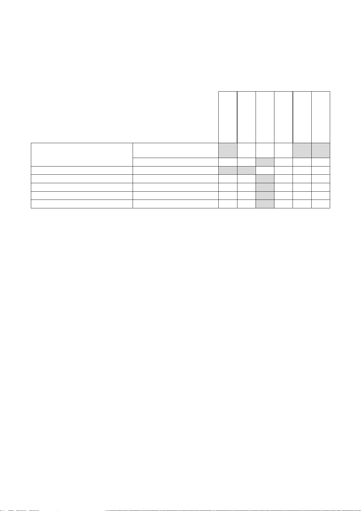
6 MAINTENANCE AND SERVICING
To ensure a long-term quality from the cutting with the TT180, please follow the maintenance plan
below:
Begin of the day
During the changing
of tool
End of the day
or more often if
required
Every week
After a fault
After a damage
Whole machine
Visual control (general aspect,
watertightness)
Clean
Flange and blade fixing devices
Clean
Motor cooling fans
Clean
Water pan
Clean
Engine housing
Clean
Reachable nuts and screws
Tighten up
Maintenance of the machine
Always perform the maintenance of the machine with the machine isolated from the electrical
supply.
Lubrication
The TT180 uses life-lubricated bearings. Therefore, you don’t need to lubricate the machine at all.
Cleaning of the machine
Your machine will last longer if you clean it thoroughly after each day of work, especially water pan,
motor and blade flange.
VERS. 2017.06.01 TT 180 BM _MAN_EN
14
7 FAULTS: CAUSES AND CURES
7.1 Fault-finding procedures
Should any fault occur during the use of the machine, turn it off, and isolate it from the electrical
supply. Any works dealing with the electrical system or supply of the machine can only be carried
out by a qualified electrician.
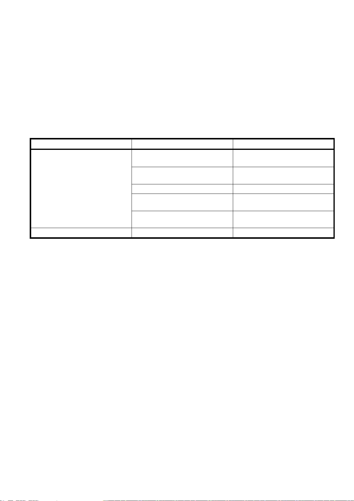
7.2 Trouble-shooting guide
Trouble
Possible source
Resolution
Motor is not running
No electricity
Check the electrical supply (fuse
for example)
Connection cable section too
small
Change connection cable
Defective connection cable
Change connection cable
Defective switch
CAUTION : can only be solved
by qualified electrician
Defective motor
Change motor or contact motor
manufacturer
No water on the blade
Not enough water in the pan
Refill the water pan

VERS. 2017.06.01 TT 180 BM _MAN_EN
15
7.3 Customer service
When ordering spare parts, please mention:
The serial number (7 digits).
The code of the part.
The exact denomination.
The number of parts required.
The delivery address.
Please indicate clearly the means of transportation required such as "express" or "by air".
Without specific instructions, we will forward the parts through the means which seem
appropriate to us --- but which is not always the quickest way.
Clear instructions will avoid problems and faulty deliveries.
If not sure, please send us the defective part.
In the case of a warranty claim, the part must always be returned for evaluation.
Spare parts for the motor can be ordered with the manufacturer of the motor or with their dealer,
which is often quicker and cheaper.
This machine has been manufactured by Saint-Gobain Abrasives S.A.
190, Bd. J.F.Kennedy
L- 4930 BASCHARAGE
Grand-Duché de Luxembourg.
Tel. : 00352-50401-1
Fax : 00352- 50 16 33
http://www.construction.norton.eu
e-mail: sales.nlx@saint-gobain.com

VERS. 2017.06.01 TT 180 BM _MAN_EN
16
Guarantee can be claimed and technical support obtained from your local distributor where
machines, spare parts and consumables can be ordered as well:

VERS. 2017.06.01 TT 180 BM _MAN_EN
17
Table of contents
Other Clipper Saw manuals

Clipper
Clipper GC25E UP User manual

Clipper
Clipper BBC157 User manual

Clipper
Clipper C13 User manual

Clipper
Clipper NORTON CS1 P13 User manual

Clipper
Clipper CM70 ALU User manual

Clipper
Clipper C65B User manual

Clipper
Clipper CM 501 HONDA User manual

Clipper
Clipper C13SPM User manual

Clipper
Clipper C13E User manual

Clipper
Clipper Jumbo 1000 P13 User manual


