Metallkraft ULMS 420 User manual

Instruction Manual
ULMS 420
Automatic light alloy metal
cutting saw
ULMS 500
ULMS 420

2ULMS-Series | Version 2.04
Imprint
Product identification
Automatic light alloy metal-cutting saw Item number
ULMS 420 3627420
ULMS 500 3627500
Manufacturer
Stürmer Maschinen GmbH
Dr.-Robert-Pfleger-Str. 26
D-96103 Hallstadt
Fax: 0 951 96555 - 55
E-Mail: [email protected]
Internet: www.metallkraft.de
Information about the operating instructions
Genuine operating instructions
according to DIN EN ISO 20607:2019
Published: 09.09.2021
Version: 2.04
Language: English
Author: MS
Copyright information
Copyright © 2021 Stürmer Maschinen GmbH, Hallstadt,
Germany.
Technical changes and errors excepted.
Contents
1 Introduction ............................................. 3
1.1 Copyright ............................................................ 3
1.2 Customer service................................................ 3
1.3 Disclaimer........................................................... 3
2 Safety ....................................................... 3
2.1 Legend of symbols.............................................. 3
2.2 Operator responsibility........................................ 4
2.3 Qualification of the staff ...................................... 4
2.4 Personal protective equipment ........................... 5
2.5 Safety data sheets .............................................. 5
2.6 General safety precautions................................. 5
2.7 Safety labels on the machine.............................. 6
3 Intended Use ........................................... 6
3.1 Reasonably foreseeable Misuse......................... 6
3.2 Residual risks ..................................................... 7
4 Technical Data......................................... 7
4.1 Table................................................................... 7
4.2 Type plate ........................................................... 9
5 Transport, Packaging, Storage .............. 9
5.1 Delivery and Transport ....................................... 9
5.2 Packaging......................................................... 10
5.3 Storage ............................................................. 10
6 Description of the Device..................... 10
6.1 Illustrations........................................................ 10
6.2 Scope of delivery .............................................. 11
7 Assembly and Installation.................... 11
7.1 Set up ............................................................... 11
7.2 Mounting the second suction nozzle................. 12
7.3 Electrical Connection........................................ 12
7.4 Installation of the cutting tool ............................ 12
7.5 Replacing the tensioning belt on the ULMS 500....13
7.6 Connection of the clamping device................... 14
7.7 Compressed air connection .............................. 14
8 Operation ............................................... 14
8.1 Settings and commissioning ............................. 14
8.2 Application of the machine................................ 15
9 Settings .................................................. 16
10 Care, Maintenance and Repairs......... 17
10.1 Cleaning and lubrication of the machine........ 18
11 Troubleshooting.................................. 19
12 Disposal, Recycling of old Equipment ..20
12.1 Decommission ............................................... 20
12.2 Disposal of electrical equipment.................... 20
12.3 Disposal of lubricants..................................... 20
12.4 Disposal via municipal collection points......... 20
13 Spare parts ......................................... 20
13.1 Spare parts orders......................................... 20
13.2 Spare parts drawings..................................... 21
14 Electrical circuit diagram ................... 33
15 EC Declaration of Conformity ............ 38
16 Notes .................................................... 39

Introduction
ULMS-Series | Version 2.04 3
1 Introduction
You have made an excellent choice in purchasing a
METALLKRAFT Automatic light alloy metal-cutting saw.
Carefully read the operating instructions prior to
commissioning.
They describe correct commissioning, intended use and
safe as well as efficient operation and maintenance of
the Automatic light alloy metal-cutting saw. The opera-
ting instructions form part of the Automatic light alloy me-
tal-cutting saw. Always keep them at the metal cutting
circular saw's location of use.
Please also observe the local accident prevention regu-
lations and general safety regulations for the use of the
Automatic light alloy metal-cutting saw. Figures in this
operation manual serve to provide a basic understanding
and may differ from the actual design.
1.1 Copyright
The contents of these instructions are protected by copy-
right and are the sole property of Stürmer Maschinen
GmbH. Their use is permitted within the scope of the use of
the underfloor light alloy circular saw. Any other use is not
permitted without the written approval of the manufacturer.
Passing on as well as duplication of this document, utili-
zation and communication of its contents are prohibited,
unless expressly permitted. Violations will result in liabi-
lity for damages. We register trademark, patent and de-
sign rights to protect our products, insofar as this is pos-
sible in individual cases. We emphatically oppose any
infringement of our intellectual property.
1.2 Customer service
Please contact your specialist retailer if you have any
questions regarding your machine or require any techni-
cal information. Your specialist retailer will be happy to
support you with specialist advice and information.
Germany:
Stürmer Maschinen GmbH
Dr.-Robert-Pfleger-Str. 26
D-96103 Hallstadt
Repair service:
Fax: 0951 96555-111
E-Mail: service@stuermer-maschinen.de
Spare parts orders:
Fax: 0951 96555-119
E-Mail: ersatzteile@stuermer-maschinen.de
Please submit any information and experiences you
make during application of the machine as these may be
valuable for product improvements.
1.3 Disclaimer
All data in this operation manual has been compiled on
the basis of the state-of-the-art, valid standards and gui-
delines as well as our many years of expertise and expe-
rience.
The manufacturer shall not be liable for damage in the
following cases:
- Failure to comply with the operation manual,
- Unintended use
- Deployment of inexperienced staff
- Conversions at one's own responsibility
- Technical modifications
- Use of unauthorised spare parts
The actual scope of delivery may deviate from the de-
scriptions and illustrations in this document as a result of
special variants, optional extras or recent, technical mo-
difications.
The obligations defined in the supply con-tract shall ap-
ply in addition to the general terms and con-ditions and
the manufacturer's general terms and condi-tions as well
as the statutory regulations valid at the time of the con-
clusion of the contract.
2 Safety
This section provides an overview of all important safety
packages for personal protection as well as safe and reli-
able operation. The individual sections contain additio-
nal, task-specific safety information.
2.1 Legend of symbols
Safety instructions
Safety instructions in this operation manual have been
highlighted with symbols. Safety instructions are indi-ca-
ted by signal terms that express the degree of risk in-
volved.

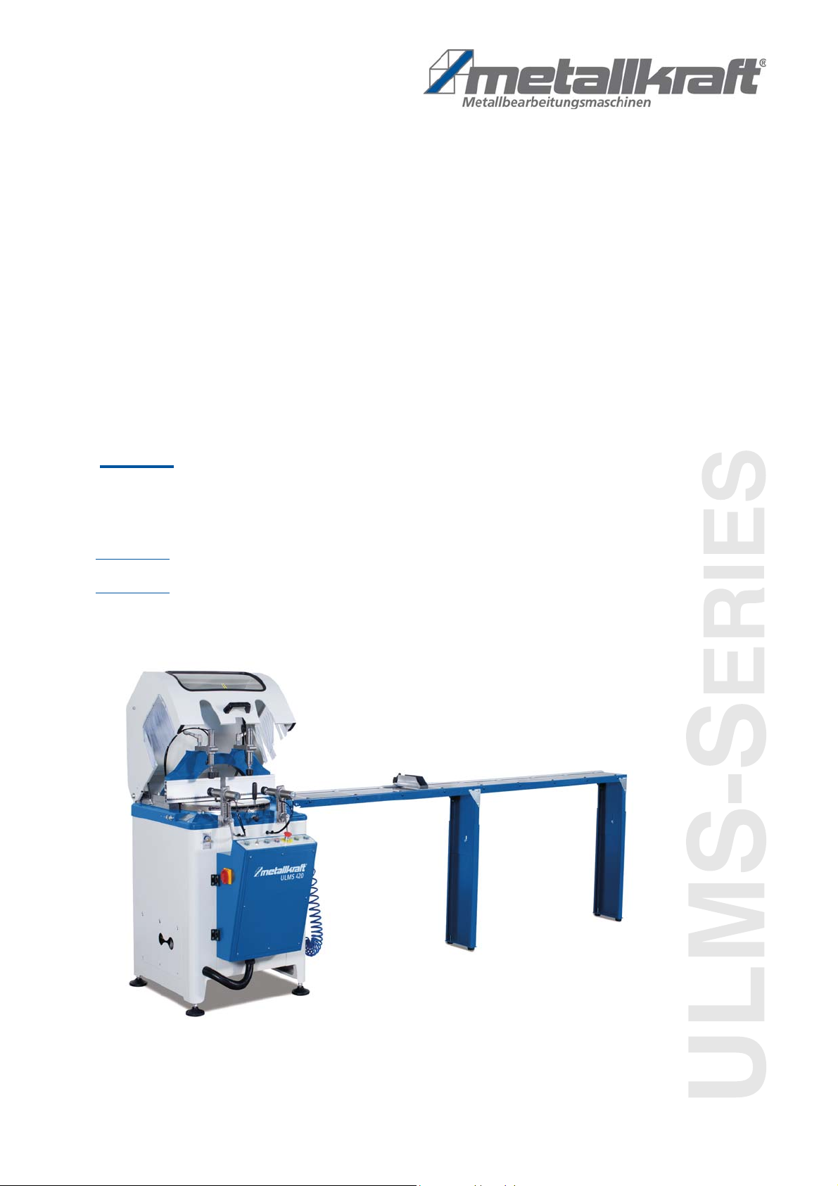
4ULMS-Series | Version 2.04
Safety
Tips and recommendations
Observe the safety information in these operating in-
structions to minimise the risk of personal injury as well
as material damage and prevent hazardous situations.
2.2 Operator responsibility
The operator is the person who operates the machine
himself for commercial purposes or who leaves it to a
third party for use or application and who bears legal pro-
duct responsibility for the protection of the user, staff or
third parties during operation.
Obligations of the operator:
If the machine is used for commercial purposes, opera-
tors are subject to the legal stipulations in terms of occu-
pational safety. For this reason, the safety instructions in
these operating instructions as well as the safety, acci-
dent prevention and environmental protection regulations
valid at the installation location must be complied with. In
this process, the following shall apply in particular:
- Operators shall obtain information about valid oc-
cupational safety regulations and determine addi-
tional hazards as part of a risk assessment which
result from the specific operating conditions at the
machine's installation location. Said risk assess-
ment shall be reflected in operating instructions for
machine operation.
- During the entire period of use of the machine, the
operator must check whether the operating instruc-
tions correspondent the current status of the regu-
lations and if necessary adapt them, adapt them if
necessary
- Operators shall clearly manage and specify the re-
sponsibilities for installation, operation, trouble-
shooting, maintenance and cleaning.
- Operators must make sure that all persons han-
dling the machine have read and understood these
operating instructions. Operators must also regu-
larly train staff and notify of the hazards.
- Operators shall provide staff with the required pro-
tective equipment and wearing the required protec-
tive equipment shall be mandatory.
Operators shall also be responsible for maintaining the
machine in a technically perfect condition. For this rea-
son, the following shall apply:
- Operators shall make sure that the maintenance in-
tervals described in these operating instructions
are complied with.
- Operators shall regularly check that the safety
equipment is fully functional and complete.
2.3 Qualification of the staff
The different tasks described in these operating instruc-
tions require different levels of skills in terms of the quali-
fications of operating staff working with the machine.
Exclusively persons of whom it can be expected that
they reliably complete assigned tasks shall be author-
ised to carry out any tasks. Persons whose reactions
have been impaired shall not be authorized, e.g. drug us-
ers, users under the influence of alcohol or medication.
DANGER!
This combination of symbol and signal word indicates
an imminently dangerous situation that will result in
death or serious injuries if it is not avoided
WARNING!
This combination of symbol and signal word indicates
a possibly dangerous situation that will result in death
or serious injuries if it is not avoided.
CAUTION!
This combination of symbol and signal word indicates
a possibly dangerous situation which can lead to
minor or light injuries if it is not avoided.
ATTENTION!
This combination of symbol and signal word indicates
a potentially dangerous situation that can lead to pro-
perty and environmental damage if it is not avoided.
NOTE!
This combination of symbol and signal term indi-
cates a potentially dangerous situation which may
cause material damage or harm the environment if it
is not averted.
Tips and recommendations
This symbol highlights useful tips and recommenda-
tions as well as information for efficient and reliable
operation.
WARNING!
Risk from inadequately qualified
persons!
Inadequately qualified persons are unable to assess
the risks when handling the machine, thus putting
themselves and others at risk of severe injuries.
- All work must be carried out by qualified persons
only.
- Keep inadequately qualified persons and children
away from the work area.

Safety
ULMS-Series | Version 2.04 5
These operating instructions specify the following per-
sonal qualifications for the different tasks:
Operating staff:
Operating staff has undergone an induction by the oper-
ator about the entrusted tasks and potential hazards re-
sulting from improper behaviour. Tasks which go beyond
normal operation may only be carried out by the operator
if they are listed in the operation manual and the opera-
tor has made him/herself familiar with them.
Qualified electrician
Due to the electrician's specialised training, know-how,
experience and knowledge of pertinent standards and
regulations the electrician is in a position to work on the
electrical systems, and autonomously identify and avoid
potential hazards.
Specialist staff:
As a result of specialist training, expertise, experience
and skills in terms of the relevant standards and regula-
tions, specialist staff is able to complete the tasks they
are entrusted with and independently identify hazards
and avert risks.
Manufacturer:
Certain work must be carried out by manufacturer spe-
cialist staff only. Other staff is not permitted to carry out
this work. Contact our customer service to have the work
carried out.
2.4 Personal protective equipment
Personal protective equipment is intended to protect the
health and safety of persons at work. Staff must wear the
personal protective equipment indicated in individual
sections of these operating instructions when carrying
out the different tasks on the machine.
The personal protective equipment is described in the
following section:
2.5 Safety data sheets
Safety data sheets for hazardous materials can be obtai-
ned from your specialist dealer or by phone: +49 (0)951/
96555-0. Specialist dealers can find safety data sheets
in the download area of the partner portal.
2.6 General safety precautions
Note the following:
- Keep the machine and its working environment al-
ways clean. Ensure adequate lighting.
- The Automatic light alloy metal-cutting saw must not
be altered in design and should not be used for pur-
poses other than those foreseen by the manufacturer.
- Never work under the influence of concentration dis-
turbing illnesses, fatigue, drugs, alcohol or medicines.
- Keep children and persons unfamiliar with the under-
floor Automatic light alloy metal-cutting saw away
from their working environment.
- Do not pull on the mains lead to pull the plug out of the
socket. Protect the cable from heat, oil and sharp edges.
- Disruptions that affect safety are eliminated immediately.
- Protect the Automatic light alloy metal-cutting saw
from moisture (risk of short circuit).
- Before using the Automatic light alloy metal-cutting
saw, make sure that no parts are damaged. Dam-
aged parts must be replaced immediately to avoid
any danger.
- Do not overload the Automatic light alloy metal-cutting
saw! You work better and safer in the specified perfor-
mance range. Use the correct saw blade! Make sure
that the saw blade is not damaged.
- Only use original spare parts and accessories to
avoid possible dangers and accident risks.
- The machine must be firmly installed to prevent acci-
dents.
Eye protection
Protective glasses protect the eyes against pro-
jected parts and splashes of liquid.
Hearing protection
Hearing protection protects the ears against hearing
damage caused by noise.
Respiratory protection
Respiratory protection serves to protect the respira-
tory tract and lungs against absorbing dust particles.
Use suitable Protective gloves
Protective gloves protect the hands from compo-
nents with sharp objects as well as friction, abrasion,
and deep-cut injuries.
Safety shoes
Safety shoes protect feet from pinching, falling parts
and slipping on slippery surfaces.
Protective clothing
Protective work clothing means tight-fitting clothing
with low tear resistance.

6ULMS-Series | Version 2.04
Intended Use
- The installation site should comply with the standards
for electrical wiring and equipment as well as the rules
set by the authorized institutions.
- The material to be processed must be fixed with the hold-
down device before the machine is put into operation.
- Safety devices such as housing, emergency stop and
safety rocker switch must never be deactivated or re-
moved.
- Use the guards and secure them securely. Never
work without protections and get them working.
- Wearing loose clothing and jewelry can be dangerous
for the operator.
- Always wear safety goggles to prevent chips from
damaging your eyes, and wear ear protection if nec-
essary to minimize the effects of extreme noise.
- The cutting tool must be properly installed.
- Do not touch cutting tools while the machine is in op-
eration.
- When working close to the cutting tools, do not wear
gloves as they may get caught in moving machine parts.
- Never operate the machine in environments where
explosive and combustible materials are present.
- Store the machine in a dry place.
- When servicing or repairing the machine, unplug the
power cord.
- The machine must be switched off after finished work.
- Chip deposits must be cleaned regularly.
- Use only recommended accessories with your device.
2.7 Safety labels on the machine
The following safety labels and instructions are attached to
the device (Fig. 1) and must be observed.
Fig. 1: Safety labels
The safety symbols attached to the machine must not be
removed. Damaged safety symbols must be re-placed
immediately.
As soon as the signs are not clearly visible and compre-
hensible at first glance, the machine must be stopped
until new labels have been attached.
3 Intended Use
The underfloor light metal circular saw is used exclusively
for sawing solid or hollow profiles made of aluminum, PVC
and wood-based materials. The underfloor light metal circu-
lar saw has been designed and built exclusively for com-
mercial use.
Intended use also includes compliance with all information
in these instructions.
3.1 Reasonably foreseeable Misuse
Any use that goes beyond the intended use or is diffe-
rent is deemed to be misuse.
Possible misuse can be:
- The underfloor light metal circular saw must not be
used to saw flammable materials (e.g. magnesium
or similar).
- Use of the underfloor light metal circular saw for
materials other than aluminum, PVC or wood-ba-
sed materials (e.g. processing hard metal or simi-
lar, plastic, etc.).
- Modifications to the machine or accessories.
- Maintenance work on an unsecured machine
- Failure to observe the signs of wear and damage.
- Service work by untrained or unauthorized person-
nel.
- Use of accessories or spare parts that are not
approved by the manufacturer.
- Improper use of the device.
- Operating the underfloor light metal circular saw if
the operating instructions have not been read and
understood in full.
- Deliberate or careless handling of the underfloor
light metal circular saw during operation.
- The use of an incompletely assembled machine.
Misuse of the underfloor light metal circular saw can lead
to dangerous situations. Stürmer Maschinen GmbH as-
sumes no liability for constructive and technical changes
to the underfloor light metal circular saw. Claims of any
kind due to damage due to improper use are excluded.
123
6
5
4

Technical Data
ULMS-Series | Version 2.04 7
3.2 Residual risks
Even if all safety regulations are observed and the de-
vice is used correctly, there are still residual risks, which
are listed below:
- Risk of injury to the upper limbs (e.g. hands, fin-
gers).
- Risk of injury from tripping over cables
- Hearing impairment when working for a long time
without hearing protection or when it is inadequate.
- Electrical hazard from contact with parts and high
voltage (direct contact) or with parts that are under
high voltage due to a defect in the underfloor light
metal circular saw (indirect contact).
- Heat development on components can lead to
burns and other injuries
- Danger from breakage or workpieces being thrown
out
- Risk of injury to the eye from flying parts, even with
protective goggles
4 Technical Data
4.1 Table
Technical Data ULMS 420 ULMS 500
Saw blade
speeds [rpm]
2900 2347
Saw blade diam-
eter [mm]
420 500
Saw blade bore
[mm]
30 30
Saw blade thick-
ness [mm]
4,0 4,0
Cutting angle [°] -45°/-30°/-22,5°/
-15°/0°/15°/
22,5°/30°/45°
-45°/-30°/-22,5°/
-15°/0°/15°/
22,5°/30°/45°
Dimensions and Weight
Length [mm] 795 855
Width / Depth
[mm]
1080 1135
Height [mm] 1325 1360
Weight [kg] 199 216
Load capacity
roller conveyor
[kg]
180 180
Engine
Engine speed
[min¯¹]
2900 2347
Drive power
Motor output
[kW]
3,0 3,0
Electrical data
Supply voltage
[V]
400 400
Phase (n) [Ph] 3 3
Current type AC AC
Mains fre-
quency [Hz]
50 50
Electrical Connection
Current con-
sumption [A]
15 15
Standards and approvals
EMV class A A
Pneumatic connection
Air requirement
approximately
[l/min]
38 38
Pneumatic work-
ing pressure
[bar]
6 - 8 6 - 8
Cutting capacity
0° (square) Full
material [mm]
120x120 155x155
-45° (square)
Full material
[mm]
100x100 130x130
+45° (square)
Full material
[mm]
100x100 130x130
Technical Data ULMS 420 ULMS 500

8ULMS-Series | Version 2.04
Technical Data
Cutting diagram and dimensions of the model ULMS
420
Fig. 2: Cutting chart ULMS 420
Fig. 3: Dimensions Model ULMS 420
Cutting diagram and dimensions of the model ULMS
500
Fig. 4: Cutting chart ULMS 500
Fig. 5: Dimensions of ULMS 500
844
1357
1134

Transport, Packaging, Storage
ULMS-Series | Version 2.04 9
Noise level
Normative reference: The noise levels generated by the
machine are based on the working conditions listed
below. EN ISO 3744 test equipment: TES 1351.
4.2 Type plate
Fig. 6: Type plate ULMS 420
5 Transport, Packaging, Storage
5.1 Delivery and Transport
Delivery
Check the Automatic light alloy metal-cutting saw for vi-
sible transport damage upon delivery. In case of visible
damage to the Automatic light alloy metal-cutting saw,
immediately notify the carrier or your retailer.
Transport
Improper transport is accident-prone and can cause da-
mage or malfunctions for which we do not grant any liabi-
lity or guarantee.Transport the scope of delivery secured
against shifting or tilting with a sufficiently dimensioned
industrial truck to the installation site
For transport, the machine must be secured in accor-
dance with the regulations on the loading area. All loose
parts must either be fixed to the machine, secured sepa-
rately or stowed in a separate, secure container.
The Automatic light alloy metal-cutting saw may only be
loaded and unloaded by qualified specialist personnel.
Test conditions ULMS 420 ULMS 500
Saw blade dia-
meter [mm]
420 500
Saw blade
speed [1/min]
2900 2347
Cutting angle [°] 90 90
Used material aluminum aluminum
Dimensions of
the material
(L x w x h)
2000 x 20 x 70
mm
2000 x 20 x 70
mm
Values while working
workplace-related
noise level (LvA)
92 dB 92 dB
Measurement
uncertainty (K)
2 dB 2 dB
WARNING!
Ear protection must be used as the sound level
during work may exceed 80 dB.
Failure to do so may damage your hearing!
WARNING!
Severe or fatal injuries may occur if parts of the
machine tumble or fall down from the forklift
truck, pallet truck or from the transport vehicle.
Follow the instructions and information on the trans-
port box.
Note the total weight of the machine. The weight of
the machine is indicated in the "Technical data" of the
machine. When the machine is unpacked, the weight
of the machine can also be read on the rating plate.
Only use transport devices and load suspension gear
that can hold the total weight of the machine.
WARNING!
The use of unstable lifting and load suspension
equipment that might break under load can cause
severe injuries or even death. Check that the lifting
and load suspension gear has sufficient load-bea-
ring capacity and that it is in perfect condition.
Observe the accident prevention regulations issued
by your Employers Liability Insurance Association or
other competent supervisory authority, responsible
for your company.
Fasten the loads properly.
NOTE!
Protect the Automatic light alloy metal-cutting saw
against moisture.
WARNING!
Danger to life due to falling of the
load!
Falling loads can cause serious injury or even death.
- Never step under suspended loads.
- Fix loads carefully.
- When leaving the workplace, lower the load.
- Absolutely avoid that the load gets into commuting.

10 ULMS-Series | Version 2.04
Description of the Device
General risks during internal transport
Devices may only be transported by authorized and qua-
lified persons. Act responsibly during transport and al-
ways consider the consequences. Refrain from daring
and risky actions.
Gradients and descents (e.g. driveways, ramps and the
like) are particularly dangerous. If such passages are
unavoidable, special caution is required.
Before starting the transport check the transport route for
possible danger points, unevenness and disturban-ces
as well as for sufficient strength and load capacity.
Danger points, unevenness and disturbance points must
be inspected before transport. The removal of danger
spots, disturbances and unevenness at the time of trans-
port by other employees leads to considerable dangers.
Careful planning of internal transport is therefore essen-
tial.
5.2 Packaging
All of the Automatic light alloy metal-cutting saw packa-
ging materi-als and packing aids are suitable for recy-
cling and must always be disposed of using material-ba-
sed recycling systems.
Packaging materials made of cardboard must be shred-
ded and recycled as waste paper.
The foils are made of polyethylene (PE), padding is
made of polystyrene (PS). Dispose of these substances
at a recycling centre or hand them over to a qualified wa-
ste disposal company.
5.3 Storage
Thoroughly clean the Automatic light alloy metal-cutting
saw in a dry, clean and frost-free environment. It must
not be shut down with chemicals in a room.
During storage, all electrical drives and control compo-
nents should be covered with a plastic film. All bare me-
tal surfaces are to be provided with a suitable rust pro-
tection.
6 Description of the Device
6.1 Illustrations
Figures in this operation manual serve to provide a
basic understanding and may differ from the actual
design.
Fig. 7: Device description ULMS 420 and ULMS 500
WARNING: DANGER OF TIPPING
The device may be lifted unsecured by a maximum
of 2cm.
Employees must be outside the danger zone, the
reach of loads.
Warn employees and, if necessary, advise employ-
ees of the hazard.
1
2
3
13
12
45
7
8
6
66
10
6
9
11

Assembly and Installation
ULMS-Series | Version 2.04 11
1 Cover with safety switch
2 Control panel
3 Pin for turning the turntable
4 Length stop
5 Scale for setting the stop frame
6 Clamping device
7 Turntables
8 Locking pin to snap in for fixed cutting angle positions
9 Miter angle scale on the turntable
10 Speed adjustment
11 Workpiece stop
12 Compressed air maintenance unit with pressure
gauge (on the side)
13 Compressed air connection (rear)
6.2 Scope of delivery
- 2x saw blade 420x30x4 mm Z96
(Model ULMS 420)
- 2x saw blade 500x30x4 mm Z120
(Model ULMS 500)
- Operating tool
- Coolant tank
- Compressed air gun and spiral hose
- Operating manual
7 Assembly and Installation
7.1 Set up
Requirements for the installation site
The machine is factory-installed and delivered to the cu-
stomer.
To ensure good functionality and a long service life of the
Automatic light alloy metal-cutting saw, the installation
site should fulfil the following criteria:
- The Automatic light alloy metal-cutting saw may
only be set up and operated in dry, frost-free, well-
ventilated rooms.
- Avoid places near chips or dust generating machines.
- The place of installation must be vibration-free, ie
away from presses, planing machines, etc.
- The substrate must be suitable for the work. Pay atten-
tion to carrying capacity and evenness of the subsoil.
- Protruding parts, such as support tables, stops,
etc., are to be secured if necessary by on-site mea-
sures so that persons are not endangered.
- Provide sufficient space for set-up and operating
personnel and material transport.
- Also consider the accessibility for adjustment and
maintenance work.
- Ensure adequate lighting (minimum value: 300 lux)
- The machine must be set up in a well-ventilated room.
Setting up the Automatic light alloy metal-cutting
saw
Model ULMS 420 and ULMS 500
Step 1: Check the surface with a spirit level for horizontal
alignment, if necessary, compensate for slight
unevenness.
Step 2: Place the supplied plastic feet in the respective
mounting slot (Fig. 8 or 9).
Step 3: Place the Automatic light alloy metal-cutting saw
on the flat, firm and vibration-free ground.
Step 4: Level the machine over the feet (Fig.8 or 9).
Fig. 8: Installation of the feet on model ULMS 420
WARNING!
Before you set up the machine, check the load-bear-
ing capacity of the substrate. The installation site
must be able to bear the weight of the machine inclu-
ding all customer-supplied parts and add-on equip-
ment, as well as the operator and the materials.
Wear suitable safety gloves!
Wear safety shoes!
Wear protective clothing!
NOTE!
The machine must be well balanced on the ground
for efficient use.
It is important that the machine is placed in a well-
ventilated area with sufficient space for easy cutting.

12 ULMS-Series | Version 2.04
Assembly and Installation
Fig. 9: Installation of the feet on model ULMS 500
7.2 Mounting the second suction
nozzle
For extracting chips from the engine compartment, it is
possible to install a second extraction socket.
Proceed as follows to mount the second suction connec-
tion.
Step 1: Turn the machine off and unplug the power cord
from the wall outlet.
Step 2: Open the cover (Pos.2, Fig.10) on the back of the
machine.
Step 3: Remove the screws and nuts attached to the
strut (Pos.3, Fig.10).
Fig. 10: Assembly of the suction connection part 1
Step 4: Remove the bracing (Pos.3, Fig.11)
Fig. 11: Assembly of the suction connection part 2
Step 5: Mount the suction connection (pos.5, fig.11) to
the strut and the machine using the screws and
nuts.
Step 6: Close the machine cover.
7.3 Electrical Connection
Make sure that the mains voltage matches the specified
voltage level of the information on the rating plate before
connecting your device to the power supply.
Also, when starting the machine, check that the direction
of rotation of the saw matches the direction of the arrow
on the machine.
7.4 Installation of the cutting tool
Replacing the saw blade on the ULMS 420 and
ULMS 500 models
NOTE!
After setting, remove the grease from the bare metal
parts, which has been applied for protection.
- Use usual solvents.
- No water, no nitrolic solvents or similar use!
NOTE!
- It is recommended to leave the device off when not
in use.
- If you need to use an extension cord, make sure it is
sufficiently thick. It is recommended to use an exten-
sion cord that is as short as possible.
- Always disconnect the mains plug before carrying
out any maintenance or repair work.
- Do not leave the unit unattended when it is
connected to the mains.

Assembly and Installation
ULMS-Series | Version 2.04 13
To mount the saw blade, proceed as follows:
Step 1: Turn the table to the 0 ° position.
Step 2: Wear protective gloves and remove component
6. Hold the saw by hand.
Step 3: First remove part 2 (fig.12).
Step 4: Next, remove parts 4 and 3, respectively.
Fig. 12: Assembly of the saw blade
Step 5: Attach Part 5 so that the small diameter side
faces Part No. 6 when the saw shaft diameter is
32 mm.
Step 6: Fix it so that the small diameter side faces the
part 4 when the saw shaft diameter is 30 mm.
Step 7: Mount the saw blade over part 5.
Step 8: Hold the saw blade by hand and tighten the allen
screw M10x20 with the Allen key.
When you have completed the above steps, the saw is
ready for operation.
7.5 Replacing the tensioning belt on the
ULMS 500
Step 1: Loosen the screws 1 with a wrench as shown in fig
13.
Step 2: Move the pulleys close to each other to remove
the belt.
Step 3: Slowly pull the belt 2 and remove it.
Step 4: Insert the new belt and repeat the process in
reverse order.
Fig. 13: Replacing the belt
DANGER!
Always unplug the power cord before changing the
saw blade.
Wear suitable safety gloves! WARNING!
Do not leave any wrenches on the machine.
NOTE!
After setting, remove the grease from the bare metal
parts, which has been applied for protection.
- Use usual solvents.
- No water, no nitrolic solvents or similar use!
WARNING!
The machine is designed for cutting aluminum and
PVC profiles.
Do not use an external cutting tool.
2
1

14 ULMS-Series | Version 2.04
Operation
7.6 Connection of the clamping device
Model ULMS 420 und ULMS 500
Pneumatic hold-down clamps automatically clamp the
workpiece as soon as the protective cover is closed. It is
crucial to hold the material to be machined in place while
cutting.
7.7 Compressed air connection
Step 1: Connect the compressed air supply line to the
connection on the rear of the machine.
Fig. 14: Compressed air connection (left) and maintenance unit with
pressure gauge (right)
Step 2: Set the desired working pressure (6 - 8 bar) on the
compressed air regulator.
8Operation
8.1 Settings and commissioning
Connecting to the mains
WARNING!
Position the hold-down clamps so that they do not
come into contact with the saw blade
WARNING!
Danger due to insufficient qualifica-
tion of persons!
Insufficiently qualified personnel can not assess the
risks involved in repairing the equipment and expose
themselves and others to the risk of serious injury.
WARNING!
Risk of life!
There is danger to life for the operator and other per-
sons if they do not adhere to the following rules.
- The operator may not work while under the influ-
ence of alcohol, drugs or medication.
- The operator must not work when he is tired or suf-
fering from concentration-impairing illnesses.
- The Automatic light alloy metal-cutting saw may
only be operated by one person. Other persons
must keep away from the work area during opera-
tion.
DANGER!
Risk of injury!
When working on the Automatic light alloy metal-cut-
ting saw
- is to wear tight-fitting clothing.
- no jewelry may be worn.
- Do not wear scarves, ties or similar.
- For long hair, a hairnet must be worn.
DANGER!
Risk of injury!
Never reach into the openings (for example, bet-
ween saw blade and housing) on the machine, as
long as it is connected to the power supply!
Wear ear protection!
Wear safety glasses!
Wear safety shoes!
Wear protective clothing!
DANGER!
All work on the electrical installation may only be car-
ried out by a qualified electrician.
NOTE!
Before commissioning, the following must be obser-
ved.
- The mains voltage must correspond to the voltage
specifications on the rating plate.
- The main switch must be set to "0".
- The safety devices as well as the protective covers
must be functional.

Operation
ULMS-Series | Version 2.04 15
8.2 Application of the machine
Model ULMS 420 and ULMS 500
Step 1: Move the main switch from position (0) to posi-
tion (1) (fig.15).
Step 2: Set the pressure to 6 bar.
Step 3: Fix the workpiece to be cut with the hold-down on
the machine by pressing the button for clamping.
Step 4: Close the top cover for safe operation.
Step 5: Press the START button to start the engine.
Step 6: Press the MOTOR STOP button to stop the engine.
Step 7: Press the Cut Start button to move the saw up.
Step 8: Turn the cutting speed regulator to set the
upward speed of the saw blade. (Cutting feed
rate of the saw blade).
You can adjust the speed during the cutting process ac-
cording to the condition of the workpiece.
Fig. 15: MAIN switch on the side of the control panel
Step 9: The saw blade moves in automatically.
Step 10: If you need to move in the saw earlier, simply
press the Cut STOP button.
Step 11: Turn off the power switch when you stop using
the machine.
Control panel model ULMS 420 and ULMS 500
Fig. 16: Control panell ULMS 420
1 START button to activate the cutting process
2 Saw oil adjustment valve
3 MOTOR start
4 EMERGENCY STOP switch
5 Cutting speed valve
6 Hold downs
7 Cutting start
Cutting process
Step 1: Adjust the clamp height according to the height
of the workpiece (1) (2) (Fig. 17).
Step 2: Place the workpiece correctly on the table and
aligned with the clamping device on the work-
piece stop 3 (Fig. 17), and then press the clamp
key
Step 3: Close the protective cover (the machine will not
start cutting if the protective cover is not closed).
Step 4: Press the engine START button.
Step 5: Press the START BUTTON for the cutting process.
The saw will start cutting the workpiece (do not for-
get to set the cutting speed).
Step 6: The saw will automatically start to lower after the
cutting process is over.
Step 7: You can adjust the position of the clamping de-
vice (1, 2, 3; Fig. 17) to the workpiece by moving
the clamp carrier back and forth (Fig. 18).
You can check the position of the clamp bracket
with the scale on the table.
DANGER!
Keep your hands away from the cutting tools. Never
try to stop the saw blade with your bare hands or
another instrument.
WARNING!
Do not start the cutting process until the engine has rea-
ched the correct speed.
WARNING!
Never touch the saw blade while it is turning.
1 2 3 4 5 6 7

16 ULMS-Series | Version 2.04
Step 8: Turn off the engine by pressing the MOTOR
STOP button after the cutting process is over.
Step 9: Turn off the MAIN switch when you stop working
with the machine.
Fig. 17: Adjustment of the clamping
Fig. 18: Adjustment of the stop frame
9Settings
Adjusting the cutting angle for model ULMS 420 and
ULMS 500 (Fig.18)
The turntable can be turned to the left or right. It can be
blocked at angles of 15 ° - 22.5 ° - 30 ° - 45 ° (central po-
sition).
To rotate the table, do the following:
Step 1: First pull the locking pin 1(Fig. 19), turn the table
(turntable) with the help of the pin 3(insert the pin
into a hole on the turntable) to the desired posi-
tion and block the angular position with the loc-
king pin .
Step 2: Check that the locking pin is properly engaged.
If you intend to cut outside the angles mentioned above,
turn the turntable to the desired angle and lock its posi-
tion with the help of the clamping screw 2 (Fig. 19).
Fig. 19: Setting the cutting angle
Fine adjustment of the zero point
To fine-tune the zero point N on the turntable, loosen the
grub screw 5(Fig. 19), turn the ring 4to the right or left
and tighten the grub screw 5 again.
1
2
3
1
2
3
ATTENTION!
The support surface of the workpiece stop must be
positioned exactly in the center of the turntable for
miter cuts!
1
2
3
4
5
N

Care, Maintenance and Repairs
ULMS-Series | Version 2.04 17
Check direction of motor rotation
Fig. 20: Check the direction of motor rotation
10 Care, Maintenance and Repairs
Maintenance
All moving parts must be oiled regularly.
Check the power cord regularly and replace it when
worn.
The miter and holding devices must always be kept
clean.
After use, clean all shavings and residues that have accu-
mulated on the work surface with a dry brush.
For better results, check and sharpen the blade (if neces-
sary) regularly.
Fig. 21: Empty the tanks
DANGER!
The three phases must be connected in such a way
that the saw blade moves according to the cutting
direction shown on the housing.
DANGER!
Before starting cleaning and maintenance work of
the machine, disconnect the mains connector and
set the main switch to 0 position.
Tips and recommendations
To keep the Automatic light alloy metal-cutting saw in
a good operational condition at all times, regular care
and maintenance work must be performed.
WARNING!
Risk due to inadequately qualified
persons!
Inadequately qualified persons are unable to assess
the risks in case of repairs to the machine, thus put-
ting themselves and others at risk of severe or fatal
injuries.
All maintenance work must be carried out by quali-
fied persons only.
DANGER!
Risk of fatal injury through electric
shock!
There is a risk of fatal injury by touching live compo-
nents.
- Before starting cleaning and maintenance work, al-
ways unplug the mains connector.
- The machine's electrical equipment must be con-
nected and repaired by a qualified electrician only.
NOTE!
After cleaning, maintenance and repairs, make sure
that all panels and protective guards are once again
correctly in place on the machine and that there are
no tools on the inside or outside of the machine.
Damaged protective guards and machine parts must
be professionally repaired by an approved workshop,
or replaced.
WARNING!
Check that there is water in the transparent water
tank of the conditioner. If water is in the tank, it must
be discharged by pressing on the pin on the bottom
of the tank.

18 ULMS-Series | Version 2.04
Care, Maintenance and Repairs
10.1 Cleaning and lubrication of the
machine
.Die Unterflur-Leichtmetallkreissäge sollte grundsätzlich nach jeder Benutzung gereinigt werden.
Sweep or wipe all open machine parts with a broom or
cloth at regular intervals.
Treat bare metallic work surfaces with anti-rust spray.
10.1.1 Fill in hydraulic oil
Oil tank capacity: 1 liter
Oil: Shell Tellur C19, BP Energol HLP 10, Petrol Ofisi Spin-
dura 10, Mobil Ote Light
Fig. 22: Hydraulic oil designation and filling quantity
Cleaning and maintenance table
* Maintenace must be performed by authorized personnel
NOTE!
The machine is not covered by the warranty in case
of the following circumstances:
- Defects and defects due to used conditioner oil,
- Faults and defects due to the full and not dischar-
ged water tank
- Failures and defects resulting from the use of non-
recommended lubricants
DANGER!
- Never use solvents to clean plastic parts or painted
surfaces. A surface release and consequential da-
mage may occur.
DANGER!
All moving parts must be free from dirt, dust and
regularly lubricated or oiled (such as bolts).
DANGER!
- Never remove the chips or sanding dust with your
bare hands. There is a risk of cuts due to sharp-
edged chips.
- Never remove the chips or sanding dust with a com-
pressed air blow gun. This can lead to eye injuries
and damage components on the machine.
Maintenance
Daily operating hours
8 to 12 hours 4 to 8 hours 1 to 4 hours
Cleaning daily daily daily
Lubrication of moving parts daily 1 weeks 2 weeks
Checking the oil on the conditioner (only
for model ULMS 500)
daily 1 weeks 1 months
Check the screws and connections 1 months 2 months 3 months
Power cables and electrical equipment daily daily daily
* Repair of the electric motor 6 months 6 months 1 year
* Check of deterioration of moving parts 6 months 6 months 1 year

Troubleshooting
ULMS-Series | Version 2.04 19
11 Troubleshooting
NOTE!
If you can not solve the problems with your machine
yourself, then please contact your nearest METALL-
KRAFT dealer. Please write down the following infor-
mation from the machine or the operating instructions
in advance to help you with your problem in the best
possible way.
- Model of the machine
- Serial number of the machine
- Construction year
- Exact error description
DANGER!
If one of the following errors occurs, stop working with
the machine immediately. Before you begin trouble-
shooting, turn off the machine and unplug the power
cord. It could otherwise lead to serious injuries.
All repairs or replacement work may only be carried
out by qualified and trained specialist personnel.
Fault Possible Cause Remedy
Error at the cutting angles. Fuse not calibrated. Set the fuse after loosening the
screw that holds it in place. Turn it to
the left or right until it is in the requi-
red position. Then secure the locking
screw.
Table rotates harder than before. The turntable must be oiled or the ta-
ble is blocked with sawdust.
Clean and lubricate the turntable.
Machine can not be switched on. There is no power connected to the
machine.
Check the cable, the plug and the
power supply.
Although there is power to the ma-
chine, the engine is not working.
Engine fault. Contact the service.
Saw does not cut well. The saw blade is dull. Sharpen or replace the saw blade.
The saw blade rotates wobbly. Grat collection in front of the cou-
plings during saw blade mounting.
Disassemble the assembly and
clean each part.
The coupling is damaged due to im-
pact.
Contact the nearest dealer to replace
damaged parts with original spare
parts.
The saw blade is damaged due to an
impact.
Replace the saw blade.

20 ULMS-Series | Version 2.04
Disposal, Recycling of old Equipment
12 Disposal, Recycling of old
Equipment
In the interests of the environment, care must be taken to
ensure that all components of the machine are disposed
of in the proper and approved way.
12.1 Decommission
Disused equipment must be taken out of service immedi-
ately in order to avoid later misuse and endangering the
environment or people.
- Dispose of all environmentally hazardous fluids from
the old device.
- If necessary, disassemble the machine into mana-
geable and usable components and components.
- Supply the machine components and operating ma-
terials to the appropriate disposal channels.
12.2 Disposal of electrical equipment
Electrical equipment contains a variety of recyclable ma-
terials and environmentally harmful components. These
components must be separated and properly disposed
of. If in doubt, contact municipal waste management.If
necessary, the help of a specialized waste disposal com-
pany can be used for the treatment.
12.3 Disposal of lubricants
The disposal instructions for the lubricants used are pro-
vided by the lubricant manufacturer. If necessary, ask for
the product-specific data sheets.
12.4 Disposal via municipal collection
points
Disposal of used electrical and electronic equipment
(Applicable in the countries of the European Union and
other European countries with a separate collection sy-
stem for these appliances).
The symbol on the product or its packaging indi-
cates that this product should not be treated as
normal household waste, but must be returned
to a collection point for the recycling of electrical and
electronic equipment. By helping to properly dispose of
this product, you are protecting the environment and the
health of others. Environment and health are endangered
by improper disposal. Material recycling helps to reduce
the consumption of raw materials. For more information
about recycling this product, contact your local commu-
nity, municipal waste management, or the shop where
you purchased the product.
13 Spare parts
13.1 Spare parts orders
Spare parts are available from authorised retailers.
Always quote the following key data with your spare
parts orders:
- Device type
- Item number
- Quantity
- Designation
- Desired shipping type (post, freight, sea, air,
express)
- Shipping address
Spare parts orders without above given information can
not be considered. If the shipping method is missing,
shipping will be at the discretion of the supplier. Informa-
tion on the device type, article number and year of manu-
facture can be found on the type plate, which is attached
to the machine.
Example
The sawblade for the underfloor light metal circular saw
ULMS 420 must be ordered. The sawblade has the
number 10 in the spare parts drawing 2.
By ordering spare parts, send a copy of the spare parts
drawing (2) with the marked part (sawblade) and marked
positon number (10) to the dealer and provide the follo-
wing information:
Type of device:
Automatic light alloy metal-cutting saw
ULMS 420
Item number: 3627420
Drawing number: 2
Position number: 10
Item number of your device:
Automatic light alloy metal-cutting saw ULMS 420
3627420
Automatic light alloy metal-cutting saw ULMS 500
3627500
NOTE!
The manufacturer warranty shall be rendered void in
the event of a use of unauthorised spare parts.
DANGER!
Risk of injury caused by the use of
incorrect spare parts!
The use of incorrect or faulty spare parts may cause
risks for operating staff and damage as well as mal-
functions.
- Exclusively genuine spare parts made by the manu-
facturer or spare parts authorised by the manufac-
turer shall be used.
- Always contact the manufacturer if you are unsure.
This manual suits for next models
1
Table of contents
Other Metallkraft Saw manuals
Popular Saw manuals by other brands

stayer
stayer SCP 125 DIAMANT Original instruction manual

EINHELL
EINHELL TC-CS 860 Kit Original operating instructions

HERKULES
HERKULES TKS 2000 Translation of original operating manual

EINHELL
EINHELL TE-CS 18/89 Li operating instructions

MK Diamond Products
MK Diamond Products MK-212 Series owner's guide

Clarke
Clarke Woodworker CTS14 Operation & maintenance instructions