Delta 36-5100 T2 User manual

10-INCH CONTRACTOR TABLE SAW
www.DeltaMachinery.com
Instruction Manual
To reduce risk of serious injury, thoroughly read and comply with all warnings and instructions in this manual and on product.
KEEP THIS MANUAL NEAR YOUR SAW FOR EASY REFERENCE AND TO INSTRUCT OTHERS
36-5000 T2
36-5100 T2
36-5052 T2
36-5152 T2
Scan:
https://youtu.be/FDQxRbmFxPs
for Riving Knife Alignment video
1

TABLE OF CONTENTS
FEATURES
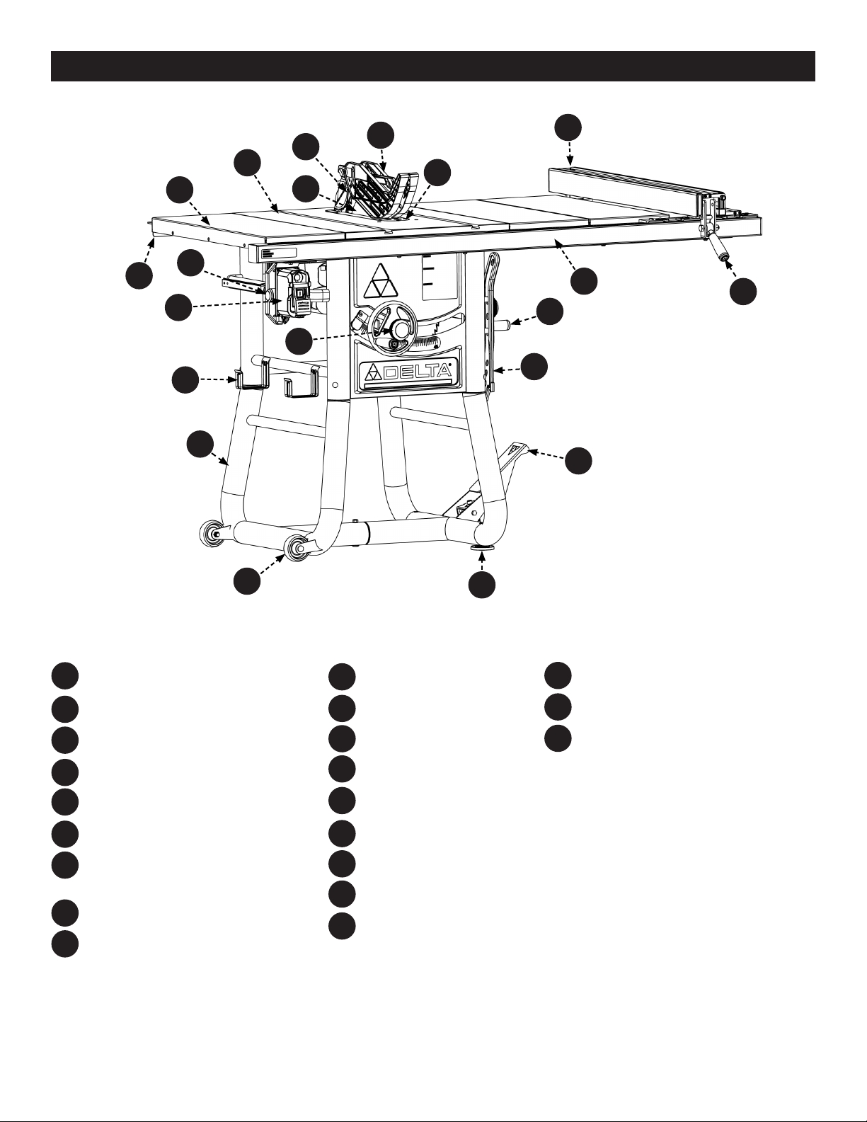
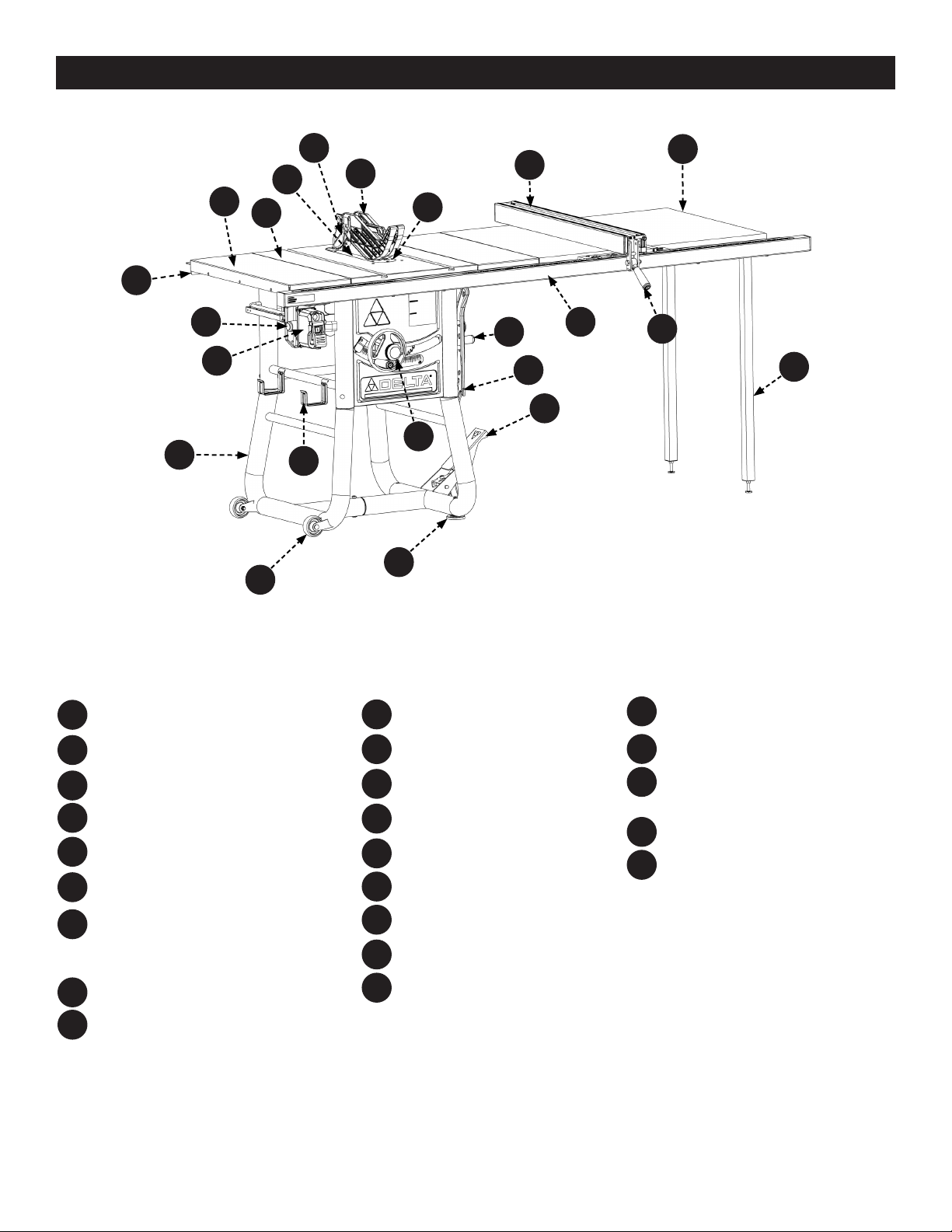
The DELTA®#36-5000 T2 series 10-inch Contractor Table Saw is
designed for portability and high quality performance. It includes:
basic machine, sturdy tubular steel stand, integral dust chute, a
T-Square®fence system, t-slot miter gauge, 15-amp induction
motor, on/off switch, cast iron table, extension wings, see through
blade guard with anti-kickback pawls, and 10-inch carbide blade.
SPECIFICATIONS
NOTICE: The manual cover illustrates the current production model. All other illustrations contained in the manual are representative
only and may not be exact depictions of the actual labeling or accessories included. They are intended for illustrative purposes only.
Max depth of cut at 90 degrees: 3 1/8 inches
Max depth of cut at 45 degrees: 2 1/4 inches
Max rip to right of blade: 30 inches or 52 inches
Max rip to left of blade: 15 inches
Max width of dado: 13/16 inches
MOTOR SPECIFICATIONS:
Amps 15
Voltage 120
No Load RPM 3,450
FEATURES............................................................................. 2
36-5000 T2 AND 36-5100 T2. ...............................................3
36-5052 T2 AND 36-5152 T2. ...............................................4
IMPORTANT SAFETY INSTRUCTIONS ................................. 5
SAFETY SYMBOLS - DEFINITIONS....................................... 5
GENERAL POWER TOOL SAFETY RULES .............................. 6
PROPOSITION 65 WARNING: ............................................. 7
TABLE SAW SAFETY RULES.................................................. 7
TERMINOLOGY..................................................................7
TABLE SAW SAFETY RULES ................................................8
SAW BLADE GUARD, ANTI-KICKBACK PAWLS AND
RIVING KNIFE ASSEMBLY.................................................10
KICKBACKS..................................................................... 10
POWER CONNECTIONS...................................................... 11
POWER SOURCE ................................................................ 11
ELECTRICAL CONNECTION................................................. 11
POLARIZED PLUGS............................................................. 11
EXTENSION CORDS ........................................................... 11
UNPACKING ....................................................................... 12
PACKAGE CONTENTS 36-5000 T2 AND 36-5100 T2.............. 13
HARDWARE PACKAGE 36-5000 T2 AND 36-5100 T2............. 14
PACKAGE CONTENTS 36-5052 T2 AND 36-5152 T2.............. 15
HARDWARE PACKAGE 36-5052 T2 AND 36-5152 T2............. 16
ASSEMBLY .......................................................................... 17
STAND............................................................................... 17
FIXED WHEELS AND STATIONARY FEET.............................. 17
FRONT AND REAR RAILS.................................................... 18
EXTENSION WINGS ........................................................... 19
WOOD EXTENSION TABLE.................................................. 20
FENCE GUIDE AND POWER CONTROL BOX ......................... 21
INSTALLING THE HANDLES ................................................ 22
INSTALLING THE RIP FENCE HANDLE................................. 22
THROAT PLATE .................................................................. 23
BLADE AND RIVING KNIFE ................................................. 23
ANTI-KICKBACK PAWLS...................................................... 24
BLADE GUARD ................................................................... 24
RIP FENCE......................................................................... 25
MITER GAUGE ................................................................... 25
ON-BOARD STORAGE......................................................... 25
SECURING SAW TO FLOOR ................................................ 25
MAKING ADJUSTMENTS .................................................... 26
ADJUSTING THE 90° AND 45° POSITIVE BEVEL STOPS ....... 26
RIVING KNIFE ALIGNMENT WITH THE BLADE..................... 27
ADJUSTING THE MITER GAUGE SCALE ............................... 28
ADJUSTING THE MITER GAUGE FITMENT ........................... 28
ALIGNING FENCE PARALLEL TO MITER SLOT ...................... 29
ALIGNING FENCE PERPENDICULAR TO THE TABLE.............. 29
DUST COLLECTION............................................................ 29
PREPARING TO CUT........................................................... 30
RAISING AND LOWERING THE BLADE ................................ 30
TILTING THE BLADE .......................................................... 30
SELECTING AND STORING SAW BLADES............................. 31
CHANGING THE SAW BLADE .............................................. 31
RIVING KNIFE POSITION ................................................... 32
RIVING KNIFE HEIGHT SETTINGS ...................................... 32
CHECKING RIVING KNIFE ALIGNMENT ............................... 33
CHECKING BLADE PARALLELISM TO MITER GAUGE
GROOVE (HEEL) ................................................................ 33
ADJUSTING BLADE PARALLELISM TO MITER GAUGE
GROOVE (HEEL) ................................................................ 33
USING THE MITER GAUGE ................................................. 34
USING BLADE GUARD ASSEMBLY........................................ 34
CHECKING FENCE ALIGNMENT........................................... 34
TRANSPORTING THE SAW.................................................. 34
OPERATION........................................................................ 35
AVOID KICKBACK............................................................... 35
STARTING AND STOPPING THE SAW .................................. 35
OVERLOAD PROTECTION ................................................... 36
MAKING CUTS .................................................................... 36
RIP CUTS .......................................................................... 37
BEVEL RIPPING.................................................................. 37
CROSSCUTTING................................................................. 38
BEVEL CROSSCUTTING ...................................................... 39
MITER CUTS...................................................................... 39
COMPOUND MITER CUTS................................................... 39
LARGE PANEL CUTS ........................................................... 39
NON-THROUGH CUTS ........................................................ 40
MAKING NON-THROUGH CUTS ........................................... 40
CUTTING AIDS AND ACCESSORIES................................... 41
PUSH STICK ...................................................................... 41
AUXILIARY RIP FENCE FACING ........................................... 41
AUXILIARY MITER GAUGE FACING...................................... 41
FLIP DOWN FENCE ............................................................ 42
PUSH BLOCKS.................................................................... 42
GROOVING AND RABBETING.............................................. 43
FEATHERBOARD ................................................................ 43
CUTOFF GAUGE ................................................................. 44
JIGS. ................................................................................. 44
MAINTENANCE................................................................... 45
KEEP MACHINE CLEAN....................................................... 45
LUBRICATION AND RUST PROTECTION .............................. 45
MAINTENANCE REMINDERS ............................................... 45
ADJUSTING BELT TENSION ................................................ 45
DUST CHUTE CLEAN OUT................................................... 46
TROUBLESHOOTING .......................................................... 47
ACCESSORIES .................................................................... 47
PARTS, SERVICES AND WARRANTY ASSISTANCE ............ 48
REPLACEMENT PARTS ........................................................ 48
FREE WARNING LABEL REPLACEMENT................................ 48
SERVICE AND REPAIRS ...................................................... 48
2

FEATURES
36-5000 T2 and 36-5100 T2 THESE CONTENTS IN
SEPARATE CARTON:
Rear Rail
Fence Guide
Front Fence Rail
(behind F20)
Table Saw
Extension Wing (3)
Switch Box
Tubular Stand
Fixed Wheels (2)
Adjustable Feet (2)
Pivoting Pedal and Caster
(attached to saw)
Lock Knobs (2)
Handwheel Handles (2)
(attached to saw)
Miter Gauge
Rip Fence Handle
Rip Fence
Throat Plate
Blade Guard
Anti-Kickback Pawls
Blade (attached to saw)
Push Stick
Fence Storage Mount
F9
F8
F19
F18
F10
F10
F11
F11
F12
F13
F12
F14
F13
F15
F14
F16
F16
F15
F17
F17
F19
F18
F20
F21
F20
F5
F5
F6
F6
F7
F7
F8
F9
F1
F1
F2
F2
F3
F3
F4
F4
NOTE: 36-5000 T2 has three Steel Extension Wings and 36-5100 T2 has two Cast Iron Extension Wings and one Steel Extension Wing.
3

FEATURES
36-5052 T2 and 36-5152 T2
Rear Rail
Fence Guide
Front Fence Rail
(behind F20)
Wood Table Extension
Legs
Table Saw
Extension Wing (2)
Switch Box
Tubular Stand
Fixed Wheels (2)
Adjustable Feet (2)
Pivoting Pedal and Caster
(attached to saw)
Lock Knobs (2)
Handwheel Handles (2)
(attached to saw)
Miter Gauge
Rip Fence Handle
Rip Fence
Throat Plate
Blade Guard
Anti-Kickback Pawls
Blade (attached to saw)
Push Stick
Fence Storage Mount
F9
F8
F10
F10
F11
F11
F12
F13
F14
F15
F16
F16
F17
F17
F19
F18
F20
F21
F5
F5
F6
F6
F7
F7
F8
F9
F1
F1
F2
F2
F3
F3
F4
F4
F22
F22
F23
F23
THESE CONTENTS IN
SEPARATE CARTON:
F12
F13
F14
F15
NOTE: THE 36-5052 T2 has two Steel Extension Wings and the 36-5152 T2 has Two Cast Iron Extension Wings.
F20
F19
F18
4

IMPORTANT SAFETY INSTRUCTIONS
CAREFULLY READ AND FOLLOW ALL WARNINGS AND INSTRUCTIONS ON YOUR PRODUCT AND IN
THIS MANUAL. SAVE THIS MANUAL. MAKE SURE ALL USERS ARE FAMILIAR WITH IT’S WARNING AND INSTRUCTIONS
WHEN USING THE TOOL. Improper operation, maintenance or modification of tools or equipment could result in serious injury and/
or property damage.
If you have any questions or concerns relative to the use of your tool or the contents of this manual, stop using the tool and contact
DELTA®Power Equipment Corporation Customer Care at 1-800-223-7278.
This manual contains information that is important for you to know and understand. This information relates to protecting YOUR
SAFETY and PREVENTING EQUIPMENT PROBLEMS. To help you recognize this information, we use the symbols below. Please read the
manual and pay attention to these sections.
Additional information regarding the safe and proper operation of this tool is available from the following sources:
• Power Tool Institute, 1300 Sumner Avenue, Cleveland, OH 44115-2851 or on-line at www.powertoolinstitute.com
• National Safety Council, 1121 Spring Lake Drive, Itasca, IL 60143-3201
• American National Standards Institute, 25 West 43rd Street, 4 oor, New York, NY 10036 www.ansi.org - ANSI 01.1 Safety
Requirements for Woodworking Machines
• U.S. Department of Labor regulations www.osha.gov
Indicates an imminently hazardous situation which, if not avoided, will result in death or serious injury.
Indicates a potentially hazardous situation which, if not avoided, could result in death or serious injury.
Indicates a potentially hazardous situation which, if not avoided, may result in minor or moderate injury.
Used without the safety alert symbol indicates potentially hazardous situation which, if not avoided, may result in
property damage.
SAFETY SYMBOLS - DEFINITIONS
Some of the following symbols may be used in connection with this product. Please study them and learn their meaning. Proper
interpretation on these symbols will allow you to operate the tool better and safer.
SYMBOL NAME DESIGNATION/EXPLANATION
Safety Alert Indicates a potential personal injury hazard.
Read Operator's Manual To reduce the risk of injury, user must read and understand operator's manual before
using this product.
Eye Protection Always wear eye protection with side shields marked to comply with ANSI Z87.1.
No Hands Symbol Failure to keep your hands away from the blade will result in serious personal injury.
Wet Conditions Alert Do not expose to rain or use in damp locations.
Pinch Warning Always watch for movement paying extra attention to potential areas where pinching
could occur.
V Volts Voltage
A Amperes Current
Hz Hertz Frequency (cycles per second)
min Minutes Time
~/AC Alternating Current Type of current
ⁿ₀No Load Speed Rotational speed, at no load
.../min Per Minute Revolutions, strokes, surface speed, orbits, etc., per minute
Lbs Pounds Unit of weight
Kg Kilograms Unit of weight
RPM Revolutions Per Minute Speed of rotation of machine
PH:1 Phase 1 This is a 1 phase motor
5

The term “power tool” in the warnings refers to your mains-operated (corded) power tool or battery-operated (cordless) power tool.
1. Work area safety
a. Keep work area clean and well lit. Cluttered or dark areas invite accidents.
b. Do not operate power tools in explosive atmospheres, such as in the presence of ammable liquids, gases
or dust. Power tools create sparks which may ignite the dust or fumes.
c. Keep children and bystanders away while operating a power tool. Distractions can cause you to lose control.
2. Electrical safety
a. Power tool plugs must match the outlet. Never modify the plug in any way. Do not use any adapter with
earthed (grounded) power tools. Unmodied plugs and matching outlets will reduce risk of electric shock.
b. Avoid body contact with earthed or grounded surfaces, such as pipes, radiators, ranges and refrigerators.
There is an increased risk of electric shock if your body is earthed or grounded.
c. Do not expose power tools to rain or wet conditions. Water entering a power tool will increase the risk of electric
shock.
d. Do not abuse the cord. Never use the cord for carrying, pulling or unplugging the power tool. Keep cord
away from heat, oil, sharp edges or moving parts. Damaged or entangled cords increase the risk of electric shock.
e. When operating a power tool outdoors, use an extension cord suitable for outdoor use. Use of a cord suitable
for outdoor use reduces the risk of electric shock.
f. If operating a power tool in a damp location is unavoidable, use a ground fault circuit interrupter (GFCI)
protected supply. Use of a GFCI reduces the risk of electric shock.
3. Personal safety
a. Stay alert, watch what you are doing and use common sense when operating a power tool. Do not use a
power tool while you are tired or under the inuence of drugs, alcohol or medication. A moment of inattention
while operating power tools may result in serious personal injury.
b. Use personal protective equipment. Always wear eye protection. Protective equipment such as dust mask, non-
skid safety shoes, hard hat, or hearing protection used for appropriate conditions will reduce personal injuries.
c. Prevent unintentional starting. Ensure the switch is in the o-position before connection to power source,
picking up, or carrying the tool. Carrying power tools with your nger on the switch or energising power tools that
have the switch on invites accidents.
d. Remove any adjusting key or wrench before turning the power tool on. A wrench or a key left attached to a
rotating part of the power tool may result in personal injury.
e. Do not overreach. Keep proper footing and balance at all times. This enables better control of the power tool in
unexpected situations.
f. Dress properly. Do not wear loose clothing or jewelery. Keep your hair, clothing and gloves away from
moving parts. Loose clothes, jewelery or long hair can be caught in moving parts.
g. If devices are provided for the connection of dust extraction and collection facilities, ensure these are
connected and properly used. Use of dust collection can reduce dust-related hazards.
h. Do not let familiarity gained from frequent use of tools allow you to become complacent and ignore tool
safety principles. A careless action can cause severe injury within a fraction of a second.
4. Power tool use and care
a. Do not force the power tool. Use the correct power tool for you application. The correct power tool will do the
job better and safer at the rate for which it was designed.
b. Do not use the power tool if the switch does not turn it on and o. Any power tool that cannot be controlled with
the switch is dangerous and must be repaired.
c. Disconnect the plug from the power source before making any adjustments, changing accessories, or
storing power tools. Such preventive safety measures reduce the risk of starting the power tool accidentally.
d. Store idle power tools out of the reach of children and do not allow persons unfamiliar with the power tool
or these instructions to operate the power tool. Power tools are dangerous in the hands of untrained users.
e. Maintain power tools and accessories. Check for misalignment or binding of moving parts , breakage of
parts and any other condition that may aect the power tool’s operation. If damaged, have the power tool
repaired before use. Many accidents are caused by poorly maintained power tools.
f. Keep cutting tools sharp and clean. Properly maintained cutting tools with sharp cutting edges are less likely to bind
and are easier to control.
g. Use the power tool, accessories and tools bits etc. in accordance with these instructions, taking into
account the working conditions and the work to be performed. Use of the power tool for operations dierent
from those intended could result in a hazardous situation.
GENERAL POWER TOOL SAFETY WARNINGS
Read all safety warnings, instructions, illustrations and specications provided with this power tool.
Failure to follow all instructions listed below may result in electric shock, re and/or serious injury.
Save all warnings and instructions for future reference.
6

PROPOSITION 65 WARNING:
SAVE THESE INSTRUCTIONS.
Refer to them often and use them to instruct others.
If tool is loaned to someone, also loan them these instructions.
Some dust created by power sanding, sawing, grinding, drilling, and other construction activities contains chemicals
known to the state of California to cause cancer, birth defects or other reproductive harm. Some examples of these chemicals are:
• Lead from lead-based paints
• Crystalline silica from bricks and cement and other masonry products
• Arsenic and chromium from chemically-treated lumber
Your risk from these exposures varies, depending on how often you do this type of work. To reduce your exposure to these chemicals:
work in a well-ventilated area and work with approved safety equipment, such as dust masks that are specifically designed to filter out
microscopic particles.
h. Keep handles and grasping surfaces dry, clean and free from oil and grease. Slippery handles and grasping
surfaces do not allow for safe handling and control of the tool in unexpected situations.
5. Service
a. Have your power tool serviced by a qualied repair person using only identical replacement parts. This will
ensure that the safety of the power tool is maintained.
GENERAL POWER TOOL SAFETY WARNINGS
• Through-cut – Any cut that completely cuts through the
workpiece.
• Non-through cut – Any cut that does not completely cut
through the workpiece.
• Push stick – A wooden or plastic stick, usually homemade,
that is used to push a small workpiece through the saw and
keeps the operator’s hands clear of the blade.
• Kickback – Occurs when the saw blade binds in the cut or
between the blade and the fence and thrusts the workpiece
back toward the operator or lowering the workpiece down to
the blade.
• Re-sawing – Flipping material to make a cut the saw is not
capable of making in one pass.
• Cove cutting – Also known as coving, cove cutting is an
operation where the work is fed at an angle across the
blade. NOTE: This can be a dangerous operation and is not
recommended.
• Freehand – Cutting without the use of a miter gauge or
rip fence or any other means of guiding or holding the
workpiece other than the operator’s hand. NOTE: This can be
a dangerous operation and is not recommended.
• Plunge cutting – Blind cuts in the workpiece made by
raising the blade through the workpiece. NOTE: This can be a
dangerous operation and is not recommended.
• Rabbet Cut – A cut on the end face (edge) of a board for
the purpose of joining two boards on the same plane. The
protruding edge is called the tongue and the recessed end is
called the groove.
• Kerf – A cut or incision made by a saw.
TABLE SAW SAFETY RULES
Failure to follow these rules may result in serious personal injury.
SEE GENERAL POWER TOOL SAFETY SECTION OF THIS MANUAL. Read entire instruction manual before operating saw. Learning
the saw’s proper applications, limitations, and specic potential hazards will greatly minimize the possibility of accidents and injury. Make
sure all users are familiar with its warnings and instructions before using saw.
SEE POWER CONNECTION SECTION OF THIS MANUAL for instructions and warnings regarding power cords and connections.
TERMINOLOGY
The following terms will be used throughout the manual and you should become familiar with them.
7

1. GUARDING RELATED WARNINGS
a. Keep guards in place. Guards must be in working order and be properly mounted. A guard that is loose,
damaged, or is not functioning correctly must be repaired or replaced.
b. Always use saw blade guard, riving knife and anti-kickback device for every through-cutting operation. For
through-cutting operations where the saw blade cuts completely through the thickness of the workpiece, the guard and
other safety devices help reduce the risk of injury.
c. Immediately reattach the guarding system after completing an operation (such as rabbeting or resawing
cuts) which requires removal of the guard, riving knife and/or anti-kickback device. The guard, riving knife,
and anti-kickback device help to reduce the risk of injury.
d. Make sure the saw blade is not contacting the guard, riving knife or the workpiece before the switch is
turned on. Inadvertent contact of these items with the saw blade could cause a hazardous condition.
e. Adjust the riving knife as described in this instruction manual. Incorrect spacing, positioning and alignment can
make the riving knife ineective in reducing the likelihood of kickback.
f. For the riving knife and anti-kickback device to work, they must be engaged in the workpiece. The riving
knife and anti-kickback device are ineective when cutting workpieces that are too short to be engaged with the
riving knife and anti-kickback device. Under these conditions a kickback cannot be prevented by the riving knife and
antikickback device.
g. Use the appropriate saw blade for the riving knife. For the riving knife to function properly, the saw blade diameter
must match the appropriate riving knife and the body of the saw blade must be thinner than the thickness of the riving
knife and kerf of the saw blade must be wider than the thickness of the riving knife.
2. CUTTING PROCEDURES WARNINGS
a. DANGER: Never place your ngers or hands in the vicinity or in line with the saw blade. A moment of
inattention or a slip could direct your hand towards the saw blade and result in serious personal injury.
b. Feed the workpiece into the saw blade or cutter only against the direction of rotation. Feeding the workpiece
in the same direction that the saw blade is rotating above the table may result in the workpiece, and your hand, being
pulled into the saw blade.
c. Never use the mitre gauge to feed the workpiece when ripping and do not use the rip fence as a length
stop when cross cutting with the miter gauge. Guiding the workpiece with the rip fence and the miter gauge at the
same time increases the likelihood of saw blade binding and kickback.
d. When ripping, always apply the workpiece feeding force between the fence and the saw blade. Use a push
stick when the distance between the fence and the saw blade is less than 50mm, and use a push block when this distance
is less than 150mm. "Work helping" devices will keep your hand at a safe distance from the saw blade.
e. Use only the push stick provided by the manufacturer or constructed in accordance with the instructions.
This push stick provides sucient distance of the hand from the saw blade.
f. Never use a damaged or cut push stick. A damaged push stick may break causing your hand to slip into the saw
blade.
g. Do not perform any operation "freehand". Always use either the rip fence or the miter gauge to position and guide
the workpiece. "Freehand" means using your hands to support or guide the workpiece, in lieu of a rip fence or mitre
gauge. Freehand sawing leads to misalignment, binding and kickback.
h. Never reach around or over a rotating saw blade. Reaching for a workpiece may lead to accidental contact with the
moving saw blade.
i. Provide auxiliary workpiece support to the rear and/or sides of the saw table for long and/or wide
workpieces to keep them level. A long and/or wide workpiece has a tendency to pivot on the table’s edge, causing
loss of control, saw blade binding and kickback.
j. Feed workpiece at an even pace. Do not bend or twist the workpiece. If jamming occurs, turn the tool o
immediately, unplug the tool then clear the jam. Jamming the saw blade by the workpiece can cause kickback or stall the
motor.
k. Do not remove pieces of cut-o material while the saw is running. The material may become trapped between
the fence or inside the saw blade guard and the saw blade pulling your ngers into the saw blade. Turn the saw o and
wait until the saw blade stops before removing material.
l. Use an auxiliary fence in contact with the table top when ripping workpieces less than 2mm thick. A thin
workpiece may wedge under the rip fence and create a kickback.
TABLE SAW SAFETY RULES
Failure to follow these rules may result in serious personal injury.
TABLE SAW SPECIFIC SAFETY RULES
WARNING READ ALL SAFETY WARNINGS DESIGNATED BY THE SYMBOL AND ALL INSTRUCTIONS.
8

TABLE SAW SAFETY RULES
m. Never Cut Metals, Cement Board or Masonry. Certain man-made materials have special instructions for cutting on
table saws. Follow the manufacturer’s recommendations at all times to avoid overheating the saw blade tips as well as
melting the plastic. Avoid overheating blade tips by pushing material through blade evenly. Forcing material too fast can
cause heating and damage to blade or workpiece. If cutting plastics is permitted, cut at a slower pace to avoid melting
the plastic.
3. Kickback causes and related warnings
Kickback is a sudden reaction of the workpiece due to a pinched, jammed saw blade or misaligned line of cut in the workpiece
with respect to the saw blade or when a part of the workpiece binds between the saw blade and the rip fence or other xed
object.
a. Most frequently during kickback, the workpiece is lifted from the table by the rear portion of the saw blade and
is propelled towards the operator. Kickback is the result of saw misuse and/or incorrect operating procedures or conditions
and can be avoided by taking proper precautions as given below.
b. Never stand directly in line with the saw blade. Always position your body on the same side of the saw blade as
the fence. Kickback may propel the workpiece at high velocity towards anyone standing in front and in line with the saw
blade.
c. Never reach over or in back of the saw blade to pull or to support the workpiece. Accidental contact with the
saw blade may occur or kickback may drag your ngers into the saw blade.
d. Never hold and press the workpiece that is being cut o against the rotating saw blade. Pressing the
workpiece being cut o against the saw blade will create a binding condition and kickback.
e. Align the fence to be parallel with the saw blade. A misaligned fence will pinch the workpiece against the saw blade
and create kickback.
f. Use a featherboard to guide the workpiece against the table and fence when making non-through cuts
such as rabbeting, or resawing cuts. A featherboard helps to control the workpiece in the event of a kickback.
g. Use extra caution when making a cut into blind areas of assembled workpieces. The protruding saw blade may
cut objects that can cause kickback.
h. Support large panels to minimise the risk of saw blade pinching and kickback. Large panels tend to sag under
their own weight. Support(s) must be placed under all portions of the panel overhanging the table top.
i. Use extra caution when cutting a workpiece that is twisted, knotted, warped or does not have a straight
edge to guide it with a mitre gauge or along the fence. A warped, knotted, or twisted workpiece is unstable and
causes misalignment of the kerf with the saw blade, binding and kickback.
j. Never cut more than one workpiece, stacked vertically or horizontally. The saw blade could pick up one or more
pieces and cause kickback.
k. When restarting the saw with the saw blade in the workpiece, centre the saw blade in the kerf so that the
saw teeth are not engaged in the material. If the saw blade binds, it may lift up the workpiece and cause kickback
when the saw is restarted.
l. Keep saw blades clean, sharp, and with sucient set. Never use warped saw blades or saw blades with cracked or
broken teeth. Sharp and properly set saw blades minimize binding, stalling and kickback.
4. Table saw operating procedure warnings
a. Turn o the table saw and disconnect the power cord when removing the table insert, changing the saw
blade or making adjustments to the riving knife, anti-kickback device or saw blade guard, and when the
machine is left unattended. Precautionary measures will avoid accidents.
b. Never leave the table saw running unattended. Turn it o and don’t leave the tool until it comes to a complete
stop. An unattended running saw is an uncontrolled hazard.
c. Locate the table saw in a well-lit and level area where you can maintain good footing and balance. It should
be installed in an area that provides enough room to easily handle the size of your workpiece. Cramped, dark areas, and
uneven slippery oors invite accidents.
d. Frequently clean and remove sawdust from under the saw table and/or the dust collection device.
Accumulated sawdust is combustible and may self-ignite.
e. The table saw must be secured. A table saw that is not properly secured may move or tip over.
f. Remove tools, wood scraps, etc. from the table before the table saw is turned on. Distraction or a potential jam
can be dangerous.
g. Always use saw blades with correct size and shape (diamond versus round) of arbor holes. Saw blades that
do not match the mounting hardware of the saw will run o-center, causing loss of control.
h. Never use damaged or incorrect saw blade mounting means such as anges, saw blade washers, bolts or
nuts. These mounting means were specially designed for your saw, for safe operation and optimum performance.
i. Never stand on the table saw, do not use it as a stepping stool. Serious injury could occur if the tool is tipped or if
the cutting tool is accidentally contacted.
9

TABLE SAW SAFETY RULES
j. Make sure that the saw blade is installed to rotate in the proper direction. Do not use grinding wheels, wire
brushes, or abrasive wheels on a table saw. Improper saw blade installation or use of accessories not recommended may
cause serious injury.
k. DO NOT REMOVE A WORKPIECE that is damaged or jammed without rst turning o the saw and unplugging it from
the power source.
SAW BLADE GUARD, ANTI-KICKBACK PAWLS AND RIVING KNIFE
ASSEMBLY
Your table saw is equipped with a blade guard, anti-kickback
pawls and riving knife assembly that covers the blade and
reduces the possibility of accidental blade contact.
The riving knife is a flat plate that fits into the cut made by
the saw blade and effectively fights kickback by lessening the
tendency of the blade to bind in the cut.
Two anti-kickback pawls are located on the sides of the riving
knife that allow the wood to pass through the blade in the cutting
direction but reduce the possibility of the material being thrown
backwards toward the operator.
The blade guard and anti-kickback pawls can ONLY be used
when making through cuts that sever the wood. When making
rabbets and other non-through cuts, the blade guard and anti-
kickback pawls MUST be removed and riving knife lowered to the
non-through cut position marked on the riving knife.
Use all components of the guarding system (blade guard
assembly, riving knife and anti-kickback pawls) for every operation
for which they can be used including all through-cutting. If
you elect not to use any of these components for a particular
application, exercise additional caution regarding control of the
workpiece, the use of push sticks, the position of your hands
relative to the blade, the use of safety glasses, the means to avoid
kickback and all other warnings contained in this manual and
on the saw itself. Replace the guarding systems as soon as you
return to through-cutting operations. KEEP the guard assembly in
working order.
KICKBACKS
Kickbacks can cause serious injury. A kickback occurs when a part
of the workpiece binds between the saw blade and the rip fence,
or other fixed object, and rises from the table and is thrown
toward the operator. Kickbacks can be minimized by attention to
the following conditions.
HOW TO REDUCE THE RISK OF KICKBACKS AND PROTECT
YOURSELF FROM POSSIBLE INJURY:
Be certain that the rip fence is parallel to the saw blade.
DO NOT rip by applying the feed force to the section of the
workpiece that will become the cut-off (free) piece. Feed force
when ripping should ALWAYS be applied between the saw
blade and the fence; use a push stick for narrow work, 6 inches
(152mm) wide or less.
KEEP saw blade guard, riving knife and anti-kickback assembly
in place and operating properly. The riving knife MUST be in
alignment with the saw blade and the anti-kickback assembly
MUST stop a kickback once it has started. Check their action
before ripping by pushing the wood under the anti-kickback
assembly. The teeth MUST prevent the wood from being pulled
toward the front of the saw. If any part of assembly is not
operational, return to the nearest authorized service center for
repair.
Plastic and composite materials (like hardboard) may be cut
on your saw. However, since these are usually quite hard and
slippery, the anti-kickback pawls may not stop a kickback.
Therefore, be especially attentive to following proper set up and
cutting procedures for ripping.
Use saw blade guard, anti-kickback pawls, and riving knife
assembly for every possible operation, including all through-cut
sawing.
Push the workpiece past the saw blade prior to releasing control.
NEVER rip a workpiece that is twisted or warped, or does not
have a straight edge to guide along the fence.
NEVER saw a large workpiece that CANNOT be controlled.
NEVER use the fence as a guide or length stop when
crosscutting.
NEVER saw a workpiece with loose knots, flaws, nails or other
foreign objects.
NEVER rip a workpiece shorter than 10 inches (254mm).
NEVER use a dull blade. A dull blade should be replaced or
re-sharpened.
10

POWER CONNECTIONS
Your machine is wired for 120 volts, 60 HZ alternating current. Before connecting the machine to the power source, make sure the
switch is in the “OFF” position.
This tool has a precision-built electric motor. It should be connected to a POWER SUPPLY THAT IS 120 VOLTS, 60 HZ, AC ONLY
(NORMAL HOUSEHOLD CURRENT in the U.S. and Canada). DO NOT operate this tool on direct current (DC). A substantial voltage
drop will cause a loss of power and the motor will overheat. If the tool does not operate when plugged into an outlet, double-check the
power supply.
To reduce the risk of electric shock, this equipment has a polarized plug (one blade is wider than the other). This plug will fit in a
polarized outlet ONLY one way. If the plug does not fully fit in the outlet reverse the plug. If it still does not fit, contact a qualified
electrician to install the proper outlet. DO NOT change the plug in any way.
When using a power tool at a considerable distance from a power source, be sure to use an extension cord that has the capacity to
handle the current the tool will draw. An undersized cord will cause a drop in line voltage, resulting in overheating and loss of power.
Use the chart to determine the minimum wire size required in an extension cord. ONLY round jacketed cords listed by Underwriter’s
Laboratories (UL) should be used.
NOTE: Before using any extension cord, inspect it for loose or
exposed wires and cut or worn insulation. ** Ampere rating (on total data label)
12A - 16A
Cord Length Wire Size
25' 14 AWG
50' 12 AWG
** Used on 12 gauge - 20 amp circuit
NOTE: AWG = American Wire Gauge
ELECTRICAL CONNECTION
POLARIZED PLUGS
EXTENSION CORDS
KEEP the extension cord clear of the work
area. Position the cord so that it will not get caught on lumber,
tools or other obstructions while you are working with a power
tool. Failure to do so can result in serious personal injury. Check
extension cords before each use. If damaged replace immediately.
NEVER use tool with a damaged cord, since touching the
damaged area could cause electrical shock resulting in serious
injury.
POWER SOURCE
This saw is equipped with a 15-amp motor for use with a 120-
volt, 60-HZ alternating current. See instructions below regarding
proper connections for your saw as wired.
For voltage, the wiring in a shop is as important as the motor’s
rating. A line intended ONLY for lights may not be able to
properly carry the current needed for a power tool motor; wire
that is heavy enough for a short distance may be too light for a
greater distance; and a line that can support one power tool may
not be able to support two or three. A separate electrical circuit
should be used for your machines. This circuit should not be less
than #12 wire and recommended to be protected with a 20-amp
circuit breaker or a 20-amp time lag fuse. If an extension cord
is used, use ONLY 3-wire extension cords which have 3-prong
grounding-type plugs and matching receptacle which will accept
the machine’s plug. Before connecting the machine to the power
line, make sure the switch is in the “OFF” position and be sure
that the electric current is of the same characteristics as indicated
on the machine. A substantial voltage drop will cause a loss of
power and overheat the motor. It may also damage the machine.
DO NOT EXPOSE THE MACHINE TO RAIN OR OPERATE THE MACHINE IN DAMP LOCATIONS.
11

UNPACKING
• The machine is heavy, two people are required to unpack and lift.
• Use a safety strap to avoid tip over when lifting machine.
• Prior to tool assembly and use, read this manual thoroughly to
familiarize yourself with proper assembly, maintenance and safety
procedures.
Check shipping carton and machine for damage before unpacking.
Carefully remove components in top foam layer. Remove the top
layer of foam then remove all components in the bottom layer of
foam. Lay out all parts on a piece of cardboard or other clean,
at surface. Two or more people are needed to lift the saw out of
the carton. ALWAYS check for and remove protective shipping
materials around motors and moving parts. DO NOT discard
shipping carton and packing materials until you have carefully
inspected the contents, assembled the machine and are satised
that it operates correctly.
Compare package contents to Package Contents list and Hardware
Package list prior to assembly to make sure all items are present.
Carefully inspect parts to make sure no damage occurred during
shipping. If any parts are missing, damaged or pre-assembled, DO
NOT assemble. Instead, call DELTA®Customer Care at 1-800-223-
7278 for assistance.
After assembly remove any protective materials and coatings from
all of the parts and the table saw. The protective coatings can be
removed by spraying WD-40® on them and wiping them o with a
soft cloth. This may need to be redone several times before all of
the protective coatings are removed completely.
After cleaning, apply a good quality paste wax to any unpainted
cast iron surfaces. Make sure to bu out the wax before operating
the saw.
12

UNPACKING
PACKAGE CONTENTS 36-5000 T2 AND 36-5100 T2
Saw Body
Left Leg
Right Leg
Rip Fence
Blade Guard
Miter Gauge
Push Stick
Throat Plate
Blade Wrench
36-5000 T2 - Steel Extension Wings (3)
36-5100 T2 - Cast Iron Extension Wings (2),
Steel Extension Wings (1)
Anti-Kickback Pawls
Adjustable Feet (2)
Fixed Wheels (2)
Hand Wheel Handles (2)
Rip Fence Handle
10 inch Blade
(Pre-Installed)
Rear Fence Rail
Front Fence Rail
Fence Guide
PC1
PC2
PC3
PC17
PC4
PC5
PC6
PC7
PC8
PC9
PC10
PC11
PC12
PC13
PC14
PC16
PC18
PC19
PC15
PC1
PC2 PC3
PC17
PC4
PC5
PC6
PC7
PC8
PC9
PC10
PC11
PC12
PC13
PC14
PC16
PC18
PC19
PC15
13

UNPACKING
HARDWARE PACKAGE 36-5000 T2 AND 36-5100 T2
HP1
HP2
HP6
HP2 HP3
HP4 HP5
HP7
HP7
Hardware Bag “A” Hardware Bag “B” Hardware Bag “D”
Hardware Bag “F”
Hardware Bag “C”
006134 007188
006111
006111
005679
007187
007187
005733
005733 003059
006122
HP15
HP14
HP14
003578
HP1
HP3
HP2 HP2
HP4
HP5
Hardware Bag “A”
M8 x 75mm Carriage Bolt
M8 Nylock Nut
M8 Flat Washer
M6 x 72mm Carriage Bolt (4)
M6 Nylock Nut (4)
Hardware Bag “B”
M8 x 53mm Carriage Bolt (2)
M8 Nylock Nut (2)
Hardware Bag “C”
5/16-18 x 7/8 Hex Screw
w/Split Lock Washer (9)
5/16-18 Hex Flange Nut (3)
5/16-18 Set Screw (4)
(Only in 36-5100 T2)
Hardware Bag “D”
5/16-18 x 1 1/8 inch Flat
Countersunk Hex Screw (6)
5/16-18 Hex Flange Nut (10)
5/16-18 x 7/8 Hex Screw
w/Split Lock Washer (6)
Hardware Bag "F"
Rail Alignment Gauge
4mm T-Handle Allen Wrench
6mm Allen Wrench
3/16 inch Two-Way Allen Wrench L
Shape
5/32 L-Shaped Hex Wrench
(Only in 36-5100 T2)
HP20
HP21
HP22
HP23
HP6
HP14
HP14
HP15
HP7
HP7
HP7
Hardware Bag “E ”
Hardware Bag “G”
007188
006111
006110
006054
007187
HP18 HP19
HP15
HP14
Hardware Bag “E”
1/4-20 x 1/2 inch Button
Head Hex Screw w/ Split Lock
Washer (4)
1/4-20 x 1/2 inch Hex Screw
w/ Split Lock Washer (2)
HP18
HP19 HP14
HP15
HP7
Hardware Bag “G”
5/16-18 x 7/8 Hex Screw
w/Split Lock Washer (2)
5/16-18 Hex Flange Nut (4)
5/16-18 x 1 1/8 inch Flat Countersunk
Hex Screw (2)
007191
HP24
HP24
HP25
007080007083 007082 007081
HP20 HP21 HP22 HP23
007193
HP25
14

UNPACKING
PACKAGE CONTENTS 36-5052 T2 AND 36-5152 T2
Saw Body
Left Leg
Right Leg
Rip Fence
Blade Guard
Miter Gauge
Push Stick
Throat Plate
Blade Wrench
36-5052 T2 - Steel Extension Wings (2)
36-5152 T2 - Cast Iron Extension Wings (2)
Anti-Kickback Pawls
Adjustable Feet (2)
Fixed Wheels (2)
Hand Wheel Handles (2)
Rip Fence Handle
10 inch Blade (Pre-Installed)
Rear Fence Rail
Front Fence Rail
Fence Guide
Wood Table Extension
Table Legs (2)
Wing Attachment Rail
PC1
PC2
PC3
PC17
PC4
PC5
PC6
PC7
PC8
PC9
PC10
PC11
PC12
PC13
PC14
PC16
PC18
PC19
PC15
PC1
PC2 PC3
PC4
PC5
PC6
PC7
PC8
PC9
PC11
PC12
PC13
PC14 PC15
PC20
PC20
PC21
PC22
PC21 PC22
PC17 PC18 PC19
PC16
PC10
15

UNPACKING
HARDWARE PACKAGE 36-5052 T2 AND 36-5152 T2
HP1 HP2 HP3
HP4 HP5
Hardware Bag “A”
005679
006054 006110
HP7
Hardware Bag “C”
007187
HP2
HP6
Hardware Bag “B”
006134
005733
005733 003059
006122
Hardware Bag “F”
003578
HP1
HP3
HP2
HP16
HP2
HP4
HP5
Hardware Bag “A”
M8 x 75mm Carriage Bolt
M8 Nylock Nut
M8 Flat Washer
M6 x 72mm Carriage Bolt (4)
M6 Nylock Nut (4)
Hardware Bag “B”
M8 x 53mm Carriage Bolt (2)
M8 Nylock Nut (2)
Hardware Bag “C”
5/16-18 x 7/8 Hex Screw
w/Split Lock Washer (6)
5/16-18 Set Screw (4)
(Only in the 36-5152 T2)
Hardware Bag “D”
5/16-18 x 1 1/8 inch Flat
Countersunk Hex Screw (6)
5/16-18 Hex Flange Nut (10)
5/16-18 x 7/8 Hex Screw
w/Split Lock Washer (6)
Hardware Bag “E”
10-32 x 34.5mm Round Head
Phillips Screw (4)
7/32 x 1/2 Flat Washer (4)
10-32 Hex Nut (4)
8-16 x 3/4 Round Head
Phillips Screw (8)
5/16-18 x 7/8 Hex Screw
w/Split Lock Washer (3)
Hardware Bag "F"
Rail Alignment Gauge
4mm T-Handle Allen Wrench
6mm Allen Wrench
3/16 inch Two-Way Allen Wrench L Shape
5/32 L-Shaped Hex Wrench
(Only in 36-5152 T2)
Hardware Bag "G"
1/4-20 x 1/2 inch Button Head Hex Screw w/
Split Lock Washer (6)
1/4-20 x 1/2 inch Hex Screw w/ Split Lock
Washer (2)
HP20
HP21
HP22
HP23
HP6
HP14
HP12
HP14
HP17
HP26
HP27
HP18
HP28
HP19
HP15 HP9
HP10
HP7
HP7
HP7
HP11
HP7
Hardware Bag “D”
007188 007187
HP15
Hardware Bag “E ”
006111
007187
HP14
HP26 HP27 HP28
HP7
HP12
HP16
HP17
HP11
HP10
HP9
8 x 16 x 1t Flat Washer (3)
5/16-18 Hex Flange Nut (3)
(Only in the 36-5052 T2)
1/4-20 x 1 1/2 Pan Head Hex
Socket Screw (6)
1/4-20 x 1-1/2 Hex Head Screw (6)
6.74 x 20.63 x 1.58 Flat Washers (12)
1/4-20 Hex Nut (12)
Hardware Bag “E”
Hardware Bag “G”
HP18 HP19
006265
006262
006263 006264
006266
003059
006268
006267
007196
HP25
HP24
007191
HP24
007080007083 007082 007081
HP20 HP21 HP22 HP23
007193
HP25
006111
HP14
16

ASSEMBLY
Avoid contact with blade teeth. KEEP blade
stored or lowered when possible.
• DO NOT lift saw without help. Hold it close to your body while
lifting. KEEP knees bent and lift with your legs, not your back.
• Fully assemble saw with leg assembly prior to use. Leg
assembly is an integral and necessary part of the support
structure for this saw.
• DO NOT modify saw, or create accessories not recommended
for use with this saw.
• Make sure power switch is in “OFF” position before connecting
to power supply.
• DO NOT connect to power supply until assembly is complete.
TOOLS REQUIRED FOR ASSEMBLY (not included)
• Flat head screwdriver
• Phillips head screwdriver
• 8mm wrench
• 10mm wrench
• 12mm wrench
• 13mm wrench
• 3/8 inch wrench
• 7/16 inch wrench
• Framing (Carpenter’s)
Square
• Combination Square
• Straight Edge
STAND
Hardware Bag “A”
1. Connect the two Tube Legs together by inserting the end
of the Left Leg PC2 into the end of the Right Leg PC3 .
Using a 13mm Wrench, secure them together with a M8 x
75mm Carriage Bolt HP1 , M8 Flat Washer H P3 , M8 Nylock
Nut HP2 and tighten. See Figure 1.
2. Insert the four open ends of the Tube Legs into the Leg
Collars Aas shown. Using a 10mm Wrench, secure each
Leg to the Saw Body with (4) M6 x 72mm Carriage Bolts
HP4 and (4) M6 Nylock Nuts HP5 and tighten. See Figure 2.
FIXED WHEELS AND STATIONARY
FEET
Hardware Bag “B”
1. Using a 13mm Wrench, attach the two Fixed Wheels PC13
to the Left Leg using the (2) M8 x 53mm Carriage Bolts
HP6 and M8 Nylock Nuts HP2 . One for each wheel as
shown in Figure 3.
2. Screw the Adjustable Feet PC12 into the threaded inserts in
the Right Leg.
3. Carefully stand the box right side up and remove packaging
once the machine has been lifted from the ground. See
Figure 4.
The machine is heavy, two people may be
required to stand the machine up.
4. The two Adjustable Feet PC12 can be raised and lowered by
rotating them clockwise or counterclockwise. The Feet
may be adjusted to level the Saw and can be locked in
place with the pre-assembled Set Screws using the
provided 6mm Allen Wrench HP22 . See Figure 3.
Figure 1
Figure 2
Figure 3
Figure 4
PC3 HP1
HP3
HP2
HP2
PC2
A
PC13
HP6
PC12
HP22
17

FRONT AND REAR RAILS
Hardware Bag “C, D”
1. Using the supplied 3/16 inch T-Handle Allen Wrench, attach
the Front Rail PC18 [1] to the table front with two 5/16-18 x
1 1/8 inch Flat Countersunk Hex Screw HP15 and two 5/16-
18 Hex Flange Nuts HP14 . See Figure 5.
2. Using the supplied 3/16 inch T-Handle Allen Wrench, attach
the Rear Rail PC17 [2] to the table back using two 5/16-18 x
7/8 inch Hex Screw with Split Lock Washer HP7 . See Figure
7.
NOTE: Use the two aligning holes which are spaced 16 inch apart
to align the front and rear rails to the table aligning holes which
are also spaced 16 inch apart.
3. Use supplied Rail Alignment Gauge HP20 to ensure the rail is
the proper distance from the top of the table at each side
of the cast iron table. See Figure 6. Figure 5
Figure 6
Figure 7
ASSEMBLY
1
2
Front RailFront Rail
Rear Rail
FRONT
BACK
HP15
HP7
HP14
HP14
PC20
18

EXTENSION WINGS
For the 36-5000 T2 and 36-5100 T2.
Hardware Bag “C, D, G”
Figure 8
Figure 9
ASSEMBLY
3
3
LEFT EXTENSIONLEFT EXTENSION
WINGWING
RIGHT EXTENSIONRIGHT EXTENSION
WINGWING
RULERRULER
PC10
HP7
HP14
HP15
HP7
HP24
PC10
1. Attach the left extension wing PC10 [3] to the front rail
using two 5/16-18 x 1-1/8 inch Flat Countersunk Hex
Screws HP15 and 5/16-18 Hex Flange Nuts HP14 .
2. Attach the left extension wing PC10 [3] to the rear rail using
two 5/16-18 x 7/8 Hex Screws w/ Split Lock Washers HP7
and 5/16-18 Hex Flange Nuts HP14 .
3. Attach the left side extension wing PC10 [3] to the front and
rear rails using four 5/16 18 x 1 1/8 inch Flat Countersunk
Hex Screw HP15 and 5/16 18 hex ange nuts HP14 .
4. Attach the left side extension wing PC10 [3] to the side of
the saw table using three 5/16 18 x 7/8 inch hex head
screws with Split Lock Washers HP7 . See Figure 10.
5. Lay the two remaining extension wings PC10 [3] upside
down on the saw table. Place the two wings adjacent to
each other, so the holes patterns match. Fasten the two
wings together using three 5/16 18 x 7/8 inch hex head
screws with Split Lock Washers HP7 and 5/16 18 hex ange
nuts HP14 .
6. Turn the two wings fastened together over and fasten
them to side of the saw table using three 5/16 18 x 7/8
inch hex head screws with Split Lock Washers HP7 . See
Figure 9.
7. Secure the 2 joined Extension Wings PC10 to the front rail
using four 5/16-18 x 1-1/8 inch Flat Countersunk Hex
Screws HP15 and 5/16-18 Hex Flange Nuts HP14 .
8. Secure the 2 joined Extension Wings PC10 to the rear rail
using four 5/16-18 x 7/8 Hex Screws w/ Split Lock Washers
HP7 and 5/16-18 Hex Flange Nuts HP14 .
NOTE: Use a ruler to make sure the top edges of the wings are
flush with the top of the tabletop. See Figure 8.
NOTE: There are four 5/16-18 Set Screws HP24 for the cast iron
extension wing for the 36-5100 T2. Two Set Screws for each cast
iron Extension Wing. The set screws are used to adjust the level.
See Figure 9.
19

ASSEMBLY
EXTENSION WINGS
For the 36-5052 T2 and 36-5152 T2
Hardware Bag “D”
Figure 10
WOOD EXTENSION TABLE
For the 36-5052 T2 and 36-5152 T2
Hardware Bag “E”
Figure 11
3
3
LEFT EXTENSIONLEFT EXTENSION
WINGWING
RIGHT EXTENSIONRIGHT EXTENSION
WINGWING
RULER
PC20
HP9
HP12
PC10
PC10
PC21
1. Lay the Wood Table Extension PC20 upside down on oor or
bench.
2. Position table legs PC21 in corner as shown in Figure 11 the
vertical wall of the angle plate on the leg should be against
the end wood wall of the table.
3. Fasten the legs to the table board with eight 8 16 x 3/4
Round Head Phillips Screw HP12 .
4. Feed four 10 32 x 34.5mm Round Head Phillips Screw HP9
with four 7/32 x 1/2 Flat Washers HP10 and 10-32 Hex Nut
HP11 through the drilled holes from the outside, then
assemble the nuts onto the screws and tighten.
1. Attach both extension wings PC10 [3] to the front rail using
four 5/16-18 x 1-1/8 inch Flat Countersunk Hex Screws
HP15 and 5/16-18 Hex Flange Nuts HP14 .
2. Attach both extension wings PC10 [3] to the rear rail using
four 5/16-18 x 7/8 Hex Screws w/ Split Lock Washers HP7
and 5/16-18 Hex Flange Nuts HP14 .
3. Attach both right extension wings PC10 [3], to the Front and
Rear rails using four 5/16-18 x 1-1/8 inch Flat Countersunk
Hex Screw HP15 and 5/16-18 Hex Flange Nuts HP14 .
4. Attach the extension wings PC10 [3] to the table using three
5/16-18 x 7/8 inch Hex Head Screws with Split Lock
Washers HP7 for each wing. See Figure 10.
NOTE: Use a ruler to make sure the top edges of the wings are
flush with the top of the tabletop. See Figure 10.
NOTE: There are four 5/16-18 Set Screws HP24 for the cast iron
extension wings for the 36-5100 T2. Two Set Screws for each cast
iron Extension Wing. The set screws are used to adjust the level.
See Figure 9.
20
This manual suits for next models
4
Table of contents
Other Delta Saw manuals

Delta
Delta 36-075 User manual

Delta
Delta SHOPMASTER 28-248 User manual

Delta
Delta 422-32-655-0004 User manual

Delta
Delta MS210 User manual

Delta
Delta 36-444 User manual

Delta
Delta 16 SM600 User manual

Delta
Delta UNISAW 34-806 User manual

Delta
Delta 36-5000 User manual

Delta
Delta Unifence 36-905 User manual

Delta
Delta 34-444 User manual

Delta
Delta 28-682 User manual

Delta
Delta SS350LS User manual

Delta
Delta SHOPMASTER SS250 User manual

Delta
Delta 36-075 User manual

Delta
Delta 36-729 User manual

Delta
Delta 36-725 T2 User manual

Delta
Delta 36-040 User manual

Delta
Delta 36-322L User manual

Delta
Delta 26-2250 User manual

Delta
Delta TwinLaser 36-255L Instruction Manual