Delton 770J User manual

DIGITAL AUTO MOTIVE ANALYSER
770J / 770K

1
Thank you for purchasing the product. Manufactured to a high
standard this product will, if used according to these instructions
and properly maintained, give you years of trouble free
performance.
1.1 PERSONAL PRECAUTIONS
√When using this multimeter, please observe all normal safety rules
concerning:
Protection against the dangers of electrical current.
Protection of the meter against misuse.
√Full compliance with safety standards can only be guaranteed if
used with the test leads supplied. If necessary, they must be
replaced with genuine The test leads supplied with the same
electronic ratings.
Failure to do so will invalidate the warranty.
× DO NOT use leads if damaged or if the wire is bared in any way.
×DO NOT use the meter if it has been damaged.
1.2 GENERAL SAFETY INSTRUCTIONS
WARNING! USE EXTREME CAUTION when working with high
voltages.
√Familiarise yourself with the application and limitations of the
multimeter as well as the potential hazards.
IF IN ANY DOUBT CONSULT A QUALIFIED ELECTRICIAN.
1. SAFETY INSTRUCTIONS
IMPORTANT: PLEASE READ THESE INSTRUCTIONS
CAREFULLY. NOTE THE SAFE OPERATIONAL
REQUIREMENTS, WARNINGS & CAUTIONS. USE THE
PRODUCT CORRECTLY AND WITH CARE FOR THE
PURPOSE FOR WHICH IT IS INTENDED. FAILURE TO DO
SO MAY CAUSE DAMAGE AND/OR PERSONAL INJURY
AND WILL INVALIDATE THE WARRANTY. PLEASE KEEP
THESE INSTRUCTIONS SAFE FOR FUTURE USE.

2
√
Before commencing testing, follow instructions below and select
the correct input sockets, function and range on the multimeter.
√
When the meter is connected to a circuit, do not touch any unused
meter terminals.
√
When the magnitude of the value to be measured is unknown
beforehand, set the range selector to the highest value available.
√
Before rotating the range selector to change functions, disconnect
test probes from the circuit under test.
WARNING! Never perform resistance, transistor, diode or
continuity measurements on live circuits.
√
Always take care when working with voltages above 35V DC or 25V
AC rms. These voltages are considered a shock hazard.
√
Always keep fingers behind the probe barriers whilst measuring
and DO NOT use when hands are wet.
×
DO NOT touch the test leads, tips or the circuit being tested.
√
Choose the proper range and function for the required
measurement. Do not try voltage or current measurements that
may exceed the ratings marked on the Function/Range switch.
√
When testing for the presence of a voltage or current, make sure
the meter is functioning correctly. Take a reading of a known voltage
or current before accepting a zero reading.
×
DO NOT test voltages above 1000V DC or 750 AC rms the circuitry
of the multimeter will be destroyed.
WARNING! NEVER connect the multimeter to a voltage source /
live circuit when the rotary switch is set to any other function apart
from Voltage testing..
WARNING! Voltage checks on electrical outlets can be difficult and
misleading because of the uncertainty of connection to the
recessed electrical contacts. Other means should be used to
ensure that the terminals are not “live”.
√
Avoid damaging the meter when testing voltage. Disconnect the
test leads from the test points before changing functions.
×
DO NOT attempt a voltage measurement with the test leads in the
20A or the mA terminal.
√
ALWAYS discharge filter capacitors in power supplies and

3
disconnect the power when making resistance or diode tests.
× DO NOT use the multimeter in a potentially explosive atmosphere
or where flammable material is present.
√ ONLY operate the multimeter when the back cover is in place and
fastened securely.
√ If any abnormal readings are observed, the multimeter must be
checked out by an authorised technician.
√ ALWAYS turn off the multimeter and disconnect the test leads,
before opening the back cover to replace the fuse or battery.
√ When not in use, store the multimeter carefully in a safe, dry,
childproof location out of direct sunlight. If storing for a long period
of time, remove the battery. Storage temperature range: -15°C to
50°C.
Note: The warnings, cautions and instructions referred to in this manual
cannot cover all possible conditions and situations that may occur.
It must be understood that common sense and caution are factors
which cannot be built into this product, but must be applied by the
operator.
WARNING! Engines produce carbon monoxide which is odourless
and causes slower reaction time which could lead to serious injury.
An engine which is operating should be in a well ventilated area, or
the vehicle's exhaust should be connected to an adequate fume
removal system.
√When working on a vehicle which is being tested or repaired ensure
that the handbrake is on and the front wheels are chocked to avoid
the vehicle moving and causing injury.
√ Wear suitable eye protection when testing or repairing a vehicle.
√ When measuring current, connect the meter in series with the load.
√ Disconnect the live test lead before disconnecting the common test
lead.
√ The mA and the 20A terminals are protected by fuses. To avoid
possible injury or damage, use only in circuits limited to 800mA or
20A for 30 seconds.
√ To maintain the accuracy of the meter, replace the discharged
battery immediately when the symbol ‘ ' appears on the meter
display.
√ Avoid measurement errors from outside interference. Keep the
meter away from spark plug and coil wires.
√ Exceeding the electrical limits of this meter is dangerous and
will expose you to serious or possibly fatal injury. Carefully
read and understand the specification limits of this meter
together with the warnings and cautions in this safety section.

4
2.INTRODUCTION & SPECIFICATION
FUNCTION TERMINAL INPUT LIMIT
DC/AC Volts,1Ohm/Continuity/Diode,
CAP., Hz, % Duty, ms Dwell, RPM VΩHz
CAT III 1000V
DC, 750V AC
rms
AC/DC Current, Type-K TEMP. mA T+ 600mA DC/AC
AC/DC 20A 20A *20A DC/AC
* 20 Amp measurement for 30 seconds maximum.
Ohms can not be measured if voltage is present, ohms can be measured
only in a non-powered circuit. However, the meter is protected to 250 volts.
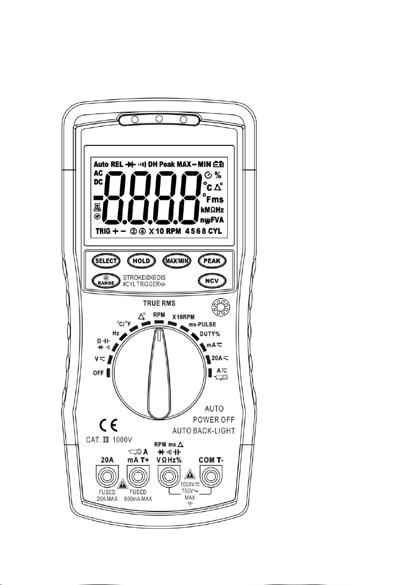
INTRODUCTION: Includes new generation, 12-function, auto-ranging
automotive diagnostic multimeter. Digital display gives accurate indication of
component outputs. Large, easy to read high contrast display with bright,
white backlight. Workshop-tough, durable bi-composite case with integral
stand and auto power shut-off. High speed processing circuitry reads
standard automotive parameters including duty cycle and pulse width making
this tool ideal for testing fuel injection systems. Features auto-ranging, and
data hold functions with overload protection on all ranges. Includes relative
functions including Min/Max and Peak Hold. Supplied with Inductive Coupler,
test probes and thermocouple in carry case.
SPECIFICATION...............................................Model No: 770J, 770K
Diode Check...........................Yes
Tach (RPM)...2-10cyl, 4-Stroke 60-9000 (x1)rpm, 600-12000 (x10)rpm
Auto Back-Light.....................Yes
Dwell:......................................................................................4/5/6/8cyl
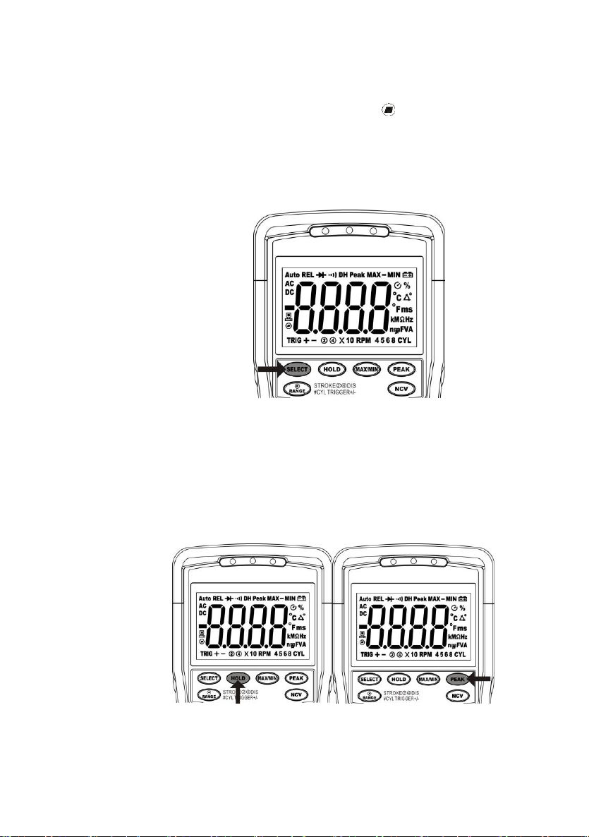
Display Hold:..........................Yes
AC Voltage:...............................................600mV, 6V, 60V, 600V, 750V
Auto Ranging:........................Yes
DC Voltage:............................................600mV, 6V, 60V, 600V, 1000V
Inductive Coupler:..................Yes
AC Current:.............................................60mA, 600mA, 6A, 20A, 600A
Digits Height:......................24mm
DC Current:.............................................60mA, 600mA, 6A, 20A, 600A
Auto Power Off.......................Yes
Capacitance:..........10nF, 100nF, 1000nF , 10μF, 100μF, 10mF, 60mF
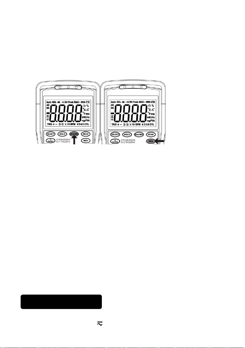
NCV detection.......................Yes
Frequency:................................................................0.001Hz-9.99MHz
Low Battery Indicator:.............Yes
Duty Cycle:.............................................................................1.0-99.0%
Batteries (supplied):.......9V (PP9)
Pulse Width:............................................................................0.1-10ms
Hi-Impact Case:......................Yes
Resistance:..........................600Ω, 6kΩ, 60kΩ, 600kΩ, 6MΩ, 60MΩ
Size (LxWxD):.......195x88x40mm
Continuity:....................................<50Ω Continuity Buzzer 2kHz
Weight(Include9V Battery):..350g
Temperature:.....................................-20 to +1000°C, -4 to +1832°F

5
3. MAIN METER FEATURES
4. PUSH BUTTON FUNCTIONS
4.1 Manual Range & Stroke
4/2(DIS), DUTY%, ms, CYL
Button(Fig 3)
Press to this button to select:
STROKE 4, 2 DIS, DUTY%,
ms-PULSE, CYL range &
V/A/R/CAP/Hz manual
Range.
Fig.3

6
Manual Ranging(Fig 3)
The meter turns on in the auto-ranging mode. Press the Range
button to go to manual ranging. The display icon " " will appear.
Each press of the range button will step to the next range as
indicated by the units and decimal point location. Press and hold
the Range button for two seconds to return to auto-ranging.
4.2 Mode Button(Fig
4)
Press the mode push
button to select the
following functions:
DC/AC Voltage & Current,
Ohm/Diode/Continuity/CA
P, ℃/℉ TEMP.
4.3 Data Hold(Fig 5a)
The Data Hold function
allows the meter to
"freeze" a measurement for later reference.
4.3.1 Press the HOLD button to “freeze” the reading on the display.
The “DH” symbol will appear in the display.
4.3.2 Press the HOLD button again to return to normal operation.
4.4 Peak
Hold (fig.
5b)
The Peak
Hold function
captures the
peak AC
voltage or
current. The
meter can capture negative or positive peaks as fast as 1.28
millisecond in duration.
4.4.1 Turn the function switch to the ACA or ACV position.
4.4.2 Press the PEAK button, Peak MAX will display.
Fig.5a
Fig.5b
Fig.4

7
5. METER FUNCTIONS
4.4.3 The display will update each time a higher positive peak
occurs.
4.4.4 Press the PEAK button again, Peak MIN will display. The
display will now update and indicate the lowest negative peak.
4.4.5 To return to normal operation, press and hold the PEAK
button until the Peak MAX or PEAK MIN indicator switches off.
4.5 MAX/MIN button (fig. 6a)
4.5.1 Press the MAX/MIN button to activate the MAX/MIN
recording mode. The display icon "MAX" will appear. Press the
MAX/MIN button again, The display icon "MIN" will appear. The
meter will go to manual ranging & display and hold the maximum
or minimum reading and will update only when a new “max or min”
occurs.
4.5.2. Press the MAX/MIN key again and a blinking “MAX MIN”
will appear. The meter will display the MAX-MIN reading,
To exit MAX/MIN mode press and hold the MAX/MIN key for 2
seconds.
4.6 NCV button (fig. 6b)
4.6.1 Press and hold the “NCV” button, the meter enters Non
Contact AC Voltage (NCV) detection, the NCV green LED light will
light up, free it to exit.
4.6.2 Free the “NCV” button to exit NCV detection.
5.1 DC or AC Voltage (DCV or ACV)
5.1.1 Select the Voltage “V” range with the rotary switch.
Fig.6a Fig.6b

8
5.1.2 Press the “SELECT” button to choose DC or AC voltage measurement.
5.1.3 The meter will automatically select the best voltage range.
5.1.4 Insert Black lead in COM terminal.
5.1.5 Insert Red lead in VΩHz terminal.
5.1.6 Touch the Black probe to ground or to the negative (-) circuit.
5.1.7 Touch the Red probe to the circuit coming from the power source.
IMPORTANT: Voltage must be measured in parallel (Red probe
measuring circuit from power source).
WARNING: When measuring voltage, be sure the Red test lead
is in the terminal marked “V”. If the test lead is in an Amp (A) or
Milliampere (mA) terminal, you may be injured or the meter
damaged.
5.2 Resistance (Ω)
IMPORTANT: If you are testing an application that has capacitors in the
circuit, be sure to turn the power OFF on the test circuit and discharge all
capacitors. Accurate measurement is not possible if external or residual
voltage is present.
5.2.1 Select the “ ” range with the rotary switch.
5.2.2 Insert Black lead in COM terminal.
5.2.3 Insert Red lead in VΩHz terminal.
5.2.4 Touch the test lead probes across the resistor to be tested.
5.3 Diode Check ( )
IMPORTANT: Turn the power OFF to the test circuit.
5.3.1 Select the " " function with the rotary switch, press the
“SELECT” button to choose Diode measurement.
5.3.2 Insert Black lead in COM terminal.
5.3.3 Insert Red lead in VΩHz terminal
5.3.4 Touch the Black test probe to the negative (-) side of the diode.
5.3.5 Touch the Red test probe to the positive (+) side of the diode.
5.3.6 Reverse the probes: Black to the positive (+) side and Red to the
negative (-) side.
Note: A "good" diode will read low in one direction and high in the other when the
probes are reversed (or vice versa). A defective diode will have the same reading in
both directions or read between 1.0 to 3.0 V. In both directions.

9
5.4 Audible Continuity ( )
IMPORTANT: Turn the power OFF on the test circuit
5.4.1 Select " " function with the rotary switch, press the
“SELECT” button to choose Audible continuity measurement.
5.4.2 Insert Black lead in COM terminal.
5.4.3 Insert Red lead in VΩHz terminal.
5.4.4 Connect one test probe to each end of the circuit to be
tested.
5.4.5 If the circuit is complete, the meter will beep continuously.
5.4.6 If the circuit is open, there is no beep and the
display shows OL (over limit).
DIODE (- to +) Reverse probes (+ to -)
GOOD 0.4 to 0.9V Over Limit (OL)
Over Limit (OL) 0.4 to 0.9V
BAD
Over Limit (OL) 1.0 to 3.0V
1.0 to 3.0V Over Limit (OL)
0.4 to 0.9V 0.4 to 0.9V
Over Limit (OL) Over Limit (OL)
0.000V 0.000V
5.5 Capacitance ( CAP )
IMPORTANT: Turn the power OFF to the test circuit
5.5.1 Select the “ " function with the rotary switch, press the
“SELECT” button to choose Capacitance measurement.
5.5.2 Insert Black lead in COM terminal.
5.5.3 Insert Red lead in VΩHz terminal.
CAUTION: When checking in-circuit capacitance, be sure that the circuit has all
power removed and all capacitors are fully discharged.
5.5.4 Touch the test lead probes across the capacitance circuit to be tested.
5.5.5 Read the measured value from the LCD Display.

10
Note:
(a) The measurement time of 10mF and 60mF modes is
a little long (MAX Aprox. 7s) .
(b) In order to obtain an accurate reading, a capacitor
must be discharged before measurement begins.
(c) Discharging through the chip is quite slow. We
recommend the user to discharge the capacitor with some other apparatus.
5.6 DC or AC Current (DCA or ACA)
IMPORTANT: All current measured flows through the
meter.It is important that you do not:
(A) Measure current greater than 600 Volts AC or DC, with
respect to ground.
(B) Do Not Exceed 30 seconds when measuring continuous
current between 1A-20A.
5.6.1 Select the “mA” or “20A” range with the rotary switch.
5.6.2 Press the “SELECT” button to select DC or AC current
measurement.
5.6.3 Insert the black lead into the COM Terminal.
5.6.4 Insert the red lead into the mAT+ or 20A terminal (select 20A if
you are unsure of the current draw).
IMPORTANT: Turn OFF all power to the circuit or
disconnect the circuit from the power source.
5.6.5 Connect the Red probe to the side of the circuit closest to the
power source.
5.6.6 Connect the Black probe to the side of the circuit to ground.
5.6.7 Turn the power ON and test.
Note: Current must always be measured with the meter test probes
connected in series, as described.

11
5-7 DC or AC 600A Current (by clamp adapter)
5.7.1 Select the “ " function with the rotary switch, it
shows symbol for testing DC current, if you want to test AC current, push
“SELECT” button switch.
5.7.2 Connect the black banana plug of the AC/DC Current Clamp
Adapter to COM terminal and the red banana plug to the mAT+
terminal.
5.7.3 Set the AC/DC Current Clamp Adapter to “1mV/A” range.
5.7.4 When perform DC current measurement, always rotate or
push the DCA zero adjuster on the Clamp Adapter until the
multimeter reads zero.
5.7.5 Clamp the Jaws around the one conductor to be measured. Center
the conductor within the Jaw using the Centering Marks as guides.
5.7.6 Read the result from the LCD panel. The arrow in the Jaw
indicates the DC current direction of positive current flow (positive to
negative).
5.8 Temperature (oC/oF) IMPORTANT: To avoid heat damage to
the meter, keep it away from sources of very high temperature. The
life of the Temperature Probe is also reduced when subjected to
very high temperatures. Probe operating range is –58º to 482 ºF.
5.8.1 Select the “ " function with the rotary switch, press the
“SELECT” button to choose ºC or ºF measurement.
5.8.2 Insert the temperature probe connector into the K-type
thermocouple adapter. Insert the adapter into the front of the meter with
the negative pin in the COM terminal socket and the positive pin in the
mAT+ terminal socket. Touch the end of the temperature sensor to the
area or surface of the object to be measured.
5.9 Frequency (Hz)
5.9.1 Select the “Hz” Frequency function with the rotary switch.
5.9.2 Insert the black lead into the COM terminal.
5.9.3 Insert the red lead into the VΩHz terminal.
5.9.4 Connect the Black test probe to ground.
5.9.5 Connect the Red test probe to the “signal out” wire of the
sensor to be Tested.

12
5.9 Frequency (Hz)
5.9.1 Select the “Hz” Frequency function with the rotary switch.
5.9.2 Insert the black lead into the COM terminal.
5.9.3 Insert the red lead into the VΩHz terminal.
5.9.4 Connect the Black test probe to ground.
5.9.5 Connect the Red test probe to the “signal out” wire of the
sensor to be Tested.
5.10 Dwell angle ( )
5.10.1 Select the “ ” function with the rotary switch.
5.10.2 Insert the Black lead into the COM terminal.
5.10.3 Insert the Red lead in VΩHz terminal.
5.10.4 Connect the Black test probe to ground.
5.10.5 Connect the Red test probe to the wire that connects to
the breaker points (see illustration).
5.11 Duty Cycle (%)
The illustration for a
mixture control solenoid is
shown with the metering
rod in the closed position.
The meter will display the
percentage of time the
plunger is in the closed
position during one duty
cycle.
5.11.1 Select the “Duty%” function with the rotary switch.
5.11.2 Insert the black lead into the COM terminal.
5.11.3 Insert the red lead into the VΩHz terminal.
5.11.4 Connect the Black test probe to ground.
5.11.5 Connect the Red test probe to the signal wire circuit.
Fig7

13
5.12 ms-PULSE (Pulse Width) & ms- PERIOD (Period)
5.12.1 Pulse Width is the length of time an actuator is energized. For
example, fuel injectors are activated by an electronic pulse from the
Engine Control Module (ECM). This pulse generates a magnetic field
that pulls the injector nozzle valve open. The pulse ends and the
injector nozzle is closed. This open to close time is the Pulse Width and
is measured in milliseconds( ms). The most common automotive
application for measuring pulse width is on fuel injectors. You can also
measure the pulse width of the fuel mixture control solenoid and the idle
air control motor.
This exercise shows how to measure Pulse Width (ms) on Port
Fuel injectors.
5.12.2 Select the “ms-PULSE” function with the rotary switch.
5.12.3 Press the Trigger± button, the negative (-) trigger slope is
displayed on the display.
NOTE: The applied time for most fuel injectors is displayed on the
negative (-) slope.
5.12.4 Insert the black lead into the COM terminal.
5.12.5 Insert the red lead into the VΩHz terminal.
5.12.6 Connect jumper wires between the fuel injector and the harness
connector.
5.12.7 Touch the Black test
probe to a good ground at
the fuel injector or the
negative (-) vehicle battery
post.
Fig8

14
5.12.8 Touch the Red test probe to the fuel injector solenoid driver
input on the jumper cable.
5.12.9 Start the engine. A pulse width in milliseconds should be
read.
Note: Initially, the unit will read “OL”, then readings will descend
and stabilize to the actual pulse width. If “OL” remains, re-check
your connections.
5.13 RPM and ×10RPM
5.13.1 Using the rotary switch, select either the RPM range or the
×10RPM range (1,000 to 12,000 RPM) and multiply the displayed
reading by ten to get actual RPM.
5.13.2 Press STROKE / DIS button to select through RPM for
4-stroke, RPM for 2-stroke and DIS ignitions.
5.13.3 Connect the inductive pickup leads to the meter.
5.13.4 Insert the black lead into the COM terminal.
5.13.5 Insert the red lead into the VΩHz terminal.
5.13.6 Open the inductive pickup and place it onto a spark plug
wire. If no reading is received, unhook the clamp, turn it over
and connect again.
Notes:
5.13.7 Position
the inductive
pick-up as far
away from the
distributor and
the exhaust
manifold as
possible.
5.13.8 Position
the inductive
pick-up to within
six inches of the
spark plug or
move it to another plug wire if no reading or an
erratic reading is received.
Fig.9

15
5.13.9 RPM 4 : For RPM of 4-stroke engines which have 1
ignition on every 4 engine Strokes
5.13.10 RPM 2 : For RPM of DIS ( Distributor less lgnition
System) & 2-stroke engines which Have 1 ignition on every 2
engine strokes
PLEASE NOTE - THE RPM PICK-UP HAS AN ADJUSTABLE
SENSITIVITY SWITCH THAT CAN ALSO BE USED TO
CORRECT AN UNSTABLE READING.
5-14 Non Contact AC Voltage (NCV) detection
5.14.1 Power on the meter, on any range, press and hold the
“NCV” key, the meter enters Non Contact AC Voltage (NCV)
detection, the NCV green LED light will light up.
5.14.2 Hold the Meter so that the mater’s top is vertically and
horizontally centered and contacting the conductor, when the live
voltage ≥ 90V AC rms, the NCV red LED light and green LED light
will light up alternately together with sound.
NOTE:
1. Even without LED indication, the voltage may still exist. Do not
rely on non-contact voltage detector to determine the presence of
voltage wire. Detection operation may be subject to socket design,
insulation thickness and different type and other factors.
2. When the meter input terminals presence voltage, due to the
influence of presence voltage, voltage sensing indicator may also
be bright.
3. Keep the meter away from electrical noise sources during the
tests, i.e., florescent lights, dimmable lights, motors, etc.. These
sources can trigger Non-Contact AC Voltage detection function
and invalidate the test.
GENERAL INSTRUMENT SPECIFICATION
Instrument complies
with IEC 1010-1 EN61010-1
Insulation Class 2, Double Insulation
Overvoltage category CATIII1000V/CATIV600V

16
6.ELECTRICAL SPECIFICATIONS
Display
6000 counts LCD display
with function indication
Polarity
Automatic, (-) negative
polarity indication.
Overrange
"OL" marks indication
Low battery indication
" " is displayed when the
battery voltage drops below
the operating level
Measurement rate
3 times per second, nominal
Auto power off
Meter automatically shuts
down after approx. 15
minutes of inactivity
Operating
environment
0oC to 50oC (32oF to 122oF)
at< 70% relative humidity.
Storage temperature
-20oC to 60oC (-4oF to
140oF) at< 80% relative
humidity.
For inside use, max
height
2000m
Pollution degree
2
Power
One 9V battery (PP9)
Dimensions
195 x 88 x 40 mm
Weight
350g (include battery)
Electrical Specification (ACCURACY).
Accuracy is given as ± ([% of reading] + [number of least
significantdigits]) at 18oC to 28oC (65oF to 83oF), with relative
humudity up to 70%.

17
Overload Protection: 0.8A / 250V and 20A / 250V Fuse Maximum
Input: 600mA DC or 600mA AC RMS on mA ranges,20A DC or AC
RMS on 20A range.
Range Resolution Accuracy
600.0mV 0.1mV ±1.5% of rdg ± 5dgts
6.000V 1mV
±1.0% of rdg ± 5dgts 60.00V 10mV
600.0V 100mV
600V/
1000V 1V ±1.5% of rdg ± 5dgts
Input Impedance: 10MΩ
AC VOLTAGE (True RMS)
Range Resolution Accuracy
600.0mV 0.1mV ±2.0% of rdg ± 10dgts
6.000V 1mV ±1.5% of rdg ± 5dgts
60.00V 10mV ±1.5% of rdg ± 8dgts
600.0V 100mV
600V/
750V 1V ±2.0% of rdg ± 4dgts
Input Impedance: 10MΩ / Frequency Range 40 to
400Hz
DC CURRENT
Range Resolution Accuracy
60.00mA 10uA ±1.5% of rdg ± 3dgts
600.0mA 100uA
20A 10mA ±2.5% of rdg ± 5dgts
600A 100mA ±3.0% of rdg ± 5dgts
DC VOLTAGE

18
DWELL ANGLE
Cylinder
Range
0.1o
±2.5% of
rdg
± 10dgts
4CYL
0 ~ 90.0o
5CYL
0 ~ 72.0o
6CYL
0 ~ 60.0o
8CYL
0 ~ 45.0o
Cylinder
Range
600A range with AC/DC Current Clamp Adapter
Overload Protection: 0.8A / 500V and 20A / 500V Fuse Frequency
Range: 40 to 400Hz.
Maximum Input:
600mA DC or 600mA AC RMS on mA ranges,20A DC or AC RMS
on 20A range.
RESISTANCE
Range
Resolution
Accuracy
600.0Ω
0.1Ω
±1.5% of rdg ± 5dgts
6.000kΩ
1Ω
±1.0% of rdg ± 5dgts
60.00kΩ
10Ω
600.0kΩ
100Ω
6.000MΩ
1kΩ
60.00MΩ
10kΩ
±2.5% of rdg ± 10dgts
AC CURRENT (True RMS)
Range Resolution Accuracy
60.00mA 10uA ±1.8% of rdg ± 5dgts
600.0mA 100uA
20A 10mA ±3.0% of rdg ± 7dgts
600A 100mA ±3.5% of rdg ± 10dgts

19
AUDIBLE CONTINUITY TEST
Audible threshold:< 50Ω
Test Current:< 1mA DC typical
RPM (Tach)
Range Resolution Accuracy
RPM
4
60 ~ 9000 RPM 1 RPM
±2.5% of
rdg
± 10dgts
600 ~ 12000
RPM. (x10 RPM) 10RPM
RPM
2/DIS
60 ~ 9000 RPM 1 RPM
600 ~ 12000
RPM. (x10 RPM) 10RPM
Effect Reading: >60RPM
DIODE TEST
Test Current Resolution Accuracy
1.0mA
typical 1mV ±5% of rdg ± 15 dgts
Open circuit voltage:3.0V DC typical
Range Resolution Accuracy
9.999nF 1pF ±2.5% of rdg ± 20dgts
99.99nF 1pF
±2.5% of rdg ± 10dgts
999.9nF 0.1nF
9.999uF 1nF
99.99uF 10nF
999.9uF 0.1uF
9.999mF 0.001mF ±10% of rdg ± 20dgts
60.00mF 10.00mF
CAPACITANCE
This manual suits for next models
1
Other Delton Measuring Instrument manuals
Popular Measuring Instrument manuals by other brands

Dakota Digital
Dakota Digital Odyssey II Series manual

Sharp
Sharp DV-RW360B Operation manual

Extech Instruments
Extech Instruments HT200 user manual

WEHRLE
WEHRLE WECOUNT RTK-OPM operating instructions

Larsen & Brusgaard
Larsen & Brusgaard ALTITRACK manual

janitza
janitza UMG 605 PRO User manual and technical data

T4W
T4W TW-2B Operation manual

JensPrima
JensPrima innoCon 6800D operating instructions

Rosemount
Rosemount SOLU COMP II instruction manual

schmersal
schmersal SRB 301X1 operating instructions

Brooks Instrument
Brooks Instrument VersaTorr BVT125 Installation & operation manual

Megger
Megger EGIL200 Series user guide