delvo DLC 1510 User manual

1
Instruction manual / Electric screwdrivers DLV 7500 / 7600 / 8500 / 8600 - DLC 1510 / 1520 / 1530 Series
Electric Screwdrivers
7500-7600 Series
8500-8600Series
INSTRUCTIONSMANUAL
DLC 1510
DLC 1520
DLC 1530

I . SAFETY PRECAUTIONS ...............................................................................p. 4
II. OPERATION CAUTIONS ...............................................................................p. 6
III . UTILISATION ..................................................................................................p. 7
Iv. AFTER SALES SERVICE AND MAINTENANCE ..........................................p. 8
- Exploded view......................................................................................................p. 10
DLV 7530 - DLV 7540 - DLV 7550 series
DLV 7630 - DLV 7640 - DLV 7650 series
- Spare parts list .....................................................................................................p. 11-12
DLV 7530 - DLV 7540 - DLV 7550 series
DLV 7630 - DLV 7640 - DLV 7650 series
- Adapter for DLV 7500 serie right angle .............................................................. p. 13
- Exploded view.....................................................................................................p. 14
DLV 8530 - DLV 8540 - DLV 8550 series
DLV 8630 - DLV 8640 - DLV 8650 series
- Spare parts list .....................................................................................................p. 15-16
DLV 8530 - DLV 8540 - DLV 8550 series
DLV 8630 - DLV 8640 - DLV 8650 series
- DLC 1510 Controller exploded view ................................................................... p. 17
- DLC 1510 Controller spare parts list ..................................................................p. 18
- DLC 1510 Controller electric scheme ................................................................. p. 19
- DLC 1520/1530 Controller exploded view .......................................................... p. 20
- DLC 1520/1530 Controller spare parts list ......................................................... p. 21
- Declaration of Conformity ...................................................................................p. 22
SUMMARY

4Instruction manual / Electric screwdrivers DLV 7500 / 7600 / 8500 / 8600 - DLC 1510 / 1520 / 1530 Series
I. SAFETY PRECAUTIONS FOR DLV 8500 SERIES
When using electric tools, basic safety precautions should always be followed to reduce the risk of fire,
electricshock andpersonal injury,includingthe following.
WARNING
1 - Consider work area environment
Donotexposethetoolsorcomponentstowaterandrain.Donotusethetoolsindampslocations.Keep
work area well lit. Do not use tool in presence of flammable liquids or gases. Keep work area clean.
Jumbled work areas and benches cause injuries.
Use safety glasses. Keep proper footing and balance at all times.
2 - Prevent operator from electric shock
Whileinuse,preventbodycontactwithgroundedsurfaces(e.g.pipes,radiators,metalstructures,or
otherelectrical appliances)
3 - Keep non-operators away
Donot permitunauthorizedpersonnel tooperatethe tool.
4 - Use the right tool
Do not use a small tool or attachment to do the job a heavy-duty tool.
5 - Do not force tool
it will do the job better and safer at the rate for which it was intended. Do not use the tool for other
purposes than fastening screws.
6 - Store idle tools
When not in use, tools should be stored in a dry and secured area.
7 - Dress properly
Donotwearlooseclothingorjewelry(necklaceetc.)becausethereisafearofbeingcaughtinmoving
parts. Wear protective hair covering to contain long hair.
8 - Do not abuse cord
Nevercarryatoolbyitscordoryankthecordtodisconnectitfromareceptable.Keepcordawayfrom
heat,oil solvents, and sharp edges.
9 - Secure Work
Useaclamporavicetoholdtheworkpiece.Operatorneedsbothhandsfreetoperformfasteningjob.

5
Instruction manual / Electric screwdrivers DLV 7500 / 7600 / 8500 / 8600 - DLC 1510 / 1520 / 1530 Series
10 - Maintain tools with care
Forsafeandefficientwork,usetheproperbitandcheckitregularly.Inspecttoolcordsperiodicallyand
ifdamaged, havethemrepaired byanauthorized servicefacility.Keep handlesdry,clean, andfree
from oil and grease.
11 - Disconnect a tool
When not in use, when repairing, when changing accessories and bits, etc...
12 - Avoid unintentional starting
Besurepowerswitchisoffbeforeconnectingthescrewdriverplug.Donotcarrythescrewdriverwith
the fingers on the switch while the tool is connected to the power.
13 - Do not use a tool violently
Donotswingthetoolaround and hold the body firmly when using. If not, it may cause injury. Do not
drop or abuse the body. If there is breakage, cracks, or transformation, it may cause injury.
14 - Startalert
Watchwhatyouaredoing.Usecommonsense.Donotusewhenyouaretired.Donotbringhandor
face close to moving parts such as bit etc when in use. Otherwise, it may cause injury.
15 - Check damaged parts
Before further using the tool, a guard, or other part that is damaged should be carefully checked to
determinethatit willoperateproperlyandperformitsintendedfunction.Checkfoalignmentofmoving
parts,bindingofmovingparts,breakageofparts,mounting,andanyotherconditionsthatmayaffect
its operation. A guard, a switch or any other part that is damaged should be properly repaired or
replacedby an authorizedservice facility.
16 - Use the designated accessories and attchments
Do not use accessories and attchments otherwise than what is mentioned in this operation manual
and/or catalogue. If used otherwise, it may cause damage or injury.
17 - Do not modify this product
We are not responsible for customer modification of the tools and components for application in
which we were not consulted.
18 - Donotallowthefollowing chemicalstocomeintocontact withthetoolhousingasdamagewillresult
:acetone, benzene, thinner, ketone, trichloroethylene or othersimilarchemicals.

6Instruction manual / Electric screwdrivers DLV 7500 / 7600 / 8500 / 8600 - DLC 1510 / 1520 / 1530 Series
II – OPERATION CAUTIONS
1–Useatthevoltagewhichisindicatedontheratingplate.Ifusedathighervoltagethanindicated,itmay
cause damageandaccident.
2 – When the tool does not work properly, or you hear abnormal sounds during usage, switch off
immediately and request the repair work to be done by an authorized service facility. If you keep
on using the tool, it may cause injury.
3 – Install only bits or accessories in accordance with the bit operation manual.
4 – Grounding is necessary to be assured, especially for the bit earth type.
5 – Whenever setting the torque, switch off the tools and components.
6 – Whenever changing the bit and brush, ensure the changeover switch is in the « O » (Off) position
andthetoolisunplugged.
7 – If the rest interval is shorter than three seconds, the heat of the motor may increase. However, it
differs from the kind of screw or from the fastening torque.
8 – Do not adjust the torque setting higher than the number of the torque scale mentioned below. The
number on the torque scale does not indicate the torque value of the screwdriver. The torque
varies according to the type, size and material of screws and work. Therefore, use the following
diagramas references toobtain an appropriatetorque.
9 – Do not operate the changeover switch when the motor is running.
10 – Do not use this screwdriver for tightening wood screws.
11 – Whenever a tool is not being used, move the changeover switch to the « O (Off) position and
unplug the screwdriver.

7
Instruction manual / Electric screwdrivers DLV 7500 / 7600 / 8500 / 8600 - DLC 1510 / 1520 / 1530 Series
III . UTILISATION
3.1 Utilisation
1-Afterconnectingthescrewdrivertothe230VAC/34VDCcontroller,connectthecontrollersocket
onthe 230V mainssupply.
2- Startupthecontrollerbyactionningtheon/offswitch.Puttherotationdirectioninversoron and
push on the screw head with the socket point. The motor starts turning.
3 - The clutch goes off as soon as the adjusted tightening torque is reached ; the motor stops
instantly.Anaudible click indicates that the screwing process is finished. Take off the bit of the
screw head.
4 - Deposit the screws.
Put the rotation direction inversor on and push on the screw head with the socket point. The
motorstartsturningintheoppositedirection.Iftheclutchgoesoff,themotorstops,soadjustthe
torque to a higher value (increase the graduation), as in normal mode.
Thisphenomenoncanbegeneratedbyimportantcoefficientsoffrictionbetweenthescrewhead
and the piece. The torque to overcome is called the « separation torque », which can be upper
tothetorqueappliedduring thescrewingoperation.
3.2 Use the screwdrivers with the following controllers :
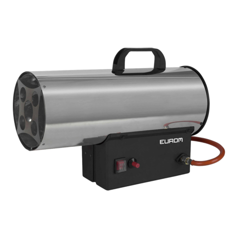
Controllers for 230V power supply .
DLC 1510 : for 1 screwdriver.
DLC 1520 : for 2 screwdrivers.
DLC 1530 : for 3 screwdrivers.
3.3 Setting and extraction of bits :
A bit can be set or taken off by practising a traction on the fast bit holder external ring.
3.4 « Torque reached » indicator :
The « torque reached » indicator indicates that the screwdriver clutch has released at theadjusted
torque.Theindicator only shows that the clutch has released, but it doesn’t warranty at 100% that
the force of pressure has been reached : for example, screw fastened the wrong way, blind hole…

8Instruction manual / Electric screwdrivers DLV 7500 / 7600 / 8500 / 8600 - DLC 1510 / 1520 / 1530 Series
3.5 «Torque reached» signal on the controller :
The 230 VAC/34VDC controller magnetic relay intervenes when the clutch has released.
The relay contacts are conected to the 1 to 3 conector pins (the pins 4 to 7 are not used).
Solder the plug which has to be conected on the controller conector and introduce the plug in
the conector.
Signal form : ON/OFF dry contact of the relay contact, as no output voltage is being generated.
4 . AFTER SALES SERVICE AND MAINTENANCE :
1 - Only qualified and trained people can repair the screwdrivers and the controllers.
2 - Ask to our after sales service, or to people trained by him, to make the controls and maintenance
definedhere-aftertoensureanoptimumfunctionning ofthematerial (each500.000fastening
operations, or after one year) :
•Control periodically the brushes of the motor carbons. Change them immediatly if their lenght is
inferior to 2.5 mm.
•Take off the carbon dust around the motor to avoid a failure due to a clogging.
•Lubricatethereductiongear.
3 - Get in touch with our after sales service in case of problem or for your repairs.
======================================================================================

9
Instruction manual / Electric screwdrivers DLV 7500 / 7600 / 8500 / 8600 - DLC 1510 / 1520 / 1530 Series
Electricscrewdriversandcontrollers
exploded views and spare parts lists

10 Instruction manual / Electric screwdrivers DLV 7500 / 7600 / 8500 / 8600 - DLC 1510 / 1520 / 1530 Series
Exploded view of
DLV 7530 – DLV 7540 – DLV 7550 Series
DLV 7630 – DLV 7640 – DLV 7650 Series

11
Instruction manual / Electric screwdrivers DLV 7500 / 7600 / 8500 / 8600 - DLC 1510 / 1520 / 1530 Series
Item Designation Reference Qty Code
1Ring 5461085K 1 4001500
2Circlips 5462316K 1 4007104
3Washer 5461051K 1 4001501
4Spring 5461050K 1 4001502
5Holder clamp 5461049K 1 4001503
6Circlips 5462712K 2 4004045
7Needle 5462735K 3 4040008
8Washer 5462315K 1 or 2 4000010
9Washer 5462312K 1 or 2 4020005
10 Assemblied nose 5461088A 1 4001600
11 Scale label 5461089K 1 4001504
12 Spacer 5461030K 1 4001505
13 Spring
For DLV 7530 5462136K 1 4004089
For DLV 7630 5461042K 1
For DLV 7540 / 7640 5464032K 1 4060143
For DLV 7550 / 7650 5464008K 1 4000025
14 Plate
For DLV 7530 / 7540 / 7550 / 7640 5461019A 1 4001601
For DLV 7630 5461020A 1 4001602
For DLV 7650 5461019B 1 4001603
15 Steel ball (Ø 3/32") 5462783K 2 4007100
16 Steel ball (Ø 5/32") 5462704K 4 4007082
17 Bits holder 5461027A 1 4001604
18 Pilot A 5461077K 1 4001506
19 Steel ball (Ø 1/16") 5462705K 1 4007083
20 Came guide 1
For DLV 7630 5461023K 1 4001507
For other models 5461022K 1 4001508
21 Steel ball (Ø 2) 5462703K 27 4002016
22 Cam 5461086K 1 4001509
23 Roller (Ø 4,5 x 4,5) 5464701K 2 4007209
24 Spacer
For DLV 8630 5461025K 1 4001510
For other models 5461087K 1 4001511
25 Ball bearing 5461035K 4001512
26 Idle gear holder
For DLV 7530 / 7540 5461036A 2 4001605
For DLV 7550 5461036A 2 4001605
For DLV 7640 5461036B 2 4001606
For DLV 7650 5461036C 2 4001607
For DLV 7630 5461036D 1 4001608
27 Idle gear holder 5461036E 1 4001609
28 Idle gear
For DLV 7530 5462116K 64020051
For DLV 7540 5462202K 6 4020025
For DLV 7550 5461093K 6 4001513
For DLV 7630 3
For DLV 7640 5464508K 6 4060154
For DLV 7650 5464513K 6 4001514
29 Spindle gear
For DLV 7530 / 7630 5461044K 1 4001515
For DLV 7540 5461045K 1 4001516
For DLV 7550 5461277K 1 4001517
For DLV 7640 5461046K 1 4001518
For DLV 7650 5461048K 1 4001519
Spare parts for
DLV 7530 – DLV 7540 – DLV 7550 Series
DLV 7630 – DLV 7640 – DLV 7650 Series

12 Instruction manual / Electric screwdrivers DLV 7500 / 7600 / 8500 / 8600 - DLC 1510 / 1520 / 1530 Series
Spare parts
Item Designation Reference Qty Code
30 Collar
For DLV 7530 5461482K 1 4060061
For DLV 7540 5461483K 1 4060064
For DLV 7550 / 7630 / 7640 / 7650 5461484K 1 4060063
31 Washer 5461018K 1 4001522
32 Pilot rod 5461052K 1 4001610
33 Motor gear
For DLV 7530 5461013K 1 4001524
For DLV 7540 5461014K 1 4001525
For DLV 7550 / 7630 5461275K 1 4001526
For DLV 7640 5461016K 1 4001527
For DLV 7650 5461017K 1 4001528
34 Pilot rod G 5461276K 1 4001529
35 Ventilator
For DLV 8630 5461152K 14001530
For other models 5462111K 14020056
36 Pilot rod J 5461012K 1 4001531
37 End cover G 5461096K 1 4001532
38 Assy ring 5461099K 1 4001533
39 Cylinder
For DLV 7530 / 7540 / 7550 5462002K 1 4004250
For DLV 7630 / 7640 / 7650 5462088K 1 4001534
40 Ball bearing 5461094K 1 4001535
41 Rotor
For DLV 7530 / 7540 / 7550 5461486K 1 4060066
For DLV 7630 5461487K 1 4060067
For DLV 7640 / 7650 5461488K 1 4060068
42 Ball bearing 5462101K 1 4004029
43 End cover (R) 5461323K 1 4001539
44 Brush assy 5461377K 2 4001540
45 Brush cap 5462106K 2 4004031
46 Pilot rod D assy 5462168K 2 4004251
47 Nut 5462709K 1 4007091
48 Adjusting screw 5462169K 1 4000069
49 Spring for pilot 5462171K 1 4007093
51 Complete plate / micro switch 5461376K 1 4060090
52 Starting micro switch 5461136K 14001541
53 Plate 5462308K 1 4030072
54 Micro switch 5461120K 14001542
55 Screw (Ø 2,3 x 12) 5462708K 4 4004252
56 Screw (Ø 2,3 x 5) 5462729K 2 4004069
57 Complete plate / reversibility 5461374A 1 4001613
58 Complete plate / reversibility 5461324K 1 4060091
59 Switch / reversibility 5461069K 1 4001543
60 For DLV7530 - orange 5462192K 1 4004090
For DLV 7640 - grey 5462191K 1 4030075
For DLV 7650 - yellow 5462194K 1 4030076
61 Led for torque reach 5461325K 1 4001544
62 Conector 5461332K 1 4001552
63 Frame A 5461321K 14001546
Frame B 1
64 Screw 5462710K 3 4004078
65 Nut 5462569K 1 4060065
66 Signaletical plate 1
67 Label 1
68 Power cord assy 5461330K 1 4001548
69 Lifting hock 5462181K 1 4004077
70 Trigger 5462313K 1 4030080
71 Spring 5462314K 1 4030081
72 Roller pin (Ø 2 x 17,8) 5462735K 1 4040008
73 Gear base assy for 7550 5461278A 4001615

13
Instruction manual / Electric screwdrivers DLV 7500 / 7600 / 8500 / 8600 - DLC 1510 / 1520 / 1530 Series
Adapter for DLV 7500 Serie right angle
Item Quantity Designation Code
4 1 Right angle 2012492
3 1 Nut 2012493
2 1 Right angle adapter 3050001
1 1 DELVO electric screwdriver
1 2 34

14 Instruction manual / Electric screwdrivers DLV 7500 / 7600 / 8500 / 8600 - DLC 1510 / 1520 / 1530 Series
Spare parts for
DLV 8530 - DLV 8540 - DLV 8550 Series
DLV 8630 - DLV 8640 - DLV 8650 Series

15
Instruction manual / Electric screwdrivers DLV 7500 / 7600 / 8500 / 8600 - DLC 1510 / 1520 / 1530 Series
Spare parts for
DLV 8530 - DLV 8540 - DLV 8550 Series
DLV 8630 - DLV 8640 - DLV 8650 Series
Item Designation Reference Qty Code
1Ring 5461085K 14001500
2 Circlips 5462316K 14007104
3Washer 5461051K 14001501
4Spring 5461050K 14001502
5Holder clamp 5461049K 14001503
6 Circlips 5462712K 24004045
7Roller pin (Ø 2 x 17,8) 5462735K 34040008
8Screwdriver output frame 5461088A 14001600
9Scale label 5461089K 14001504
10 Spacer 5461030K 14001505
11 Spring
For DLV 8530 5462136K 14004089
For DLV 8630 5461042K 1
For DLV 8540 / 8640 5464032K 14060143
For DLV 8550 / 8650 5464008K 14000025
12 Flange
For DLV 8530 / 8540 / 8550 / 8640 5461019A 14001601
For DLV 8630 5461020A 14001602
For DLV 8650 5461019B 14001603
13 Steel ball (Ø 3/32") 5462783K 24007100
14 Steel ball (Ø 5/32") 5462704K 44007082
15 Bit holder 5461027A 14001604
16 Pilot A 5461077K 14001506
17 Steel ball (Ø 1/16") 5462705K 14007083
18 Spacer 5461028K 14001549
19 Spring 5461029K 14001550
20 Guide came 1
For DLV 8630 5461023K 14001507
For other models 5461022K 14001508
21 Steel ball (Ø 2) 5462703K 27 4002016
22 Cam 5461086K 14001509
23 Roller (Ø 4,5 x 4,5) 5464701K 24007209
24 Spacer
For DLV 8630 5461025K 14001510
For other models 5461087K 14001511
25 Ball bearing 5461035K 4001512
26 Idle gear holder
For DLV 8530/8550 5461036A 24001605
For DLV 8640 5461036B 24001606
For DLV 8650 5461036C 24001607
For DLV 8630 5461036D 14001608
27 Idle gear holder 5461036E 4001609
28 Idle gear
For DLV 8530 5462116K 64020051
For DLV 8540 5462202K 64020025
For DLV 8550 5461093K 64001513
For DLV 8630 5461093K 34001513
For DLV 8640 5464508K 64060154
For DLV 8650 5464513K 64001514
29 Spindle gear
For DLV 8530 / 8630 5461044K 14001515
For DLV 8540 5461045K 14001516
For DLV 8550 5461277K 14001517
For DLV 8640 5461046K 14001518
For DLV 8650 5461048K 14001519

16 Instruction manual / Electric screwdrivers DLV 7500 / 7600 / 8500 / 8600 - DLC 1510 / 1520 / 1530 Series
Item Designation Reference Qty Code
30 Collar
For DLV 8530 5461482K 1 4060061
For DLV 8540 5461483K 1 4060064
For DLV 8550 / 8630 / 8640 / 8650 5461484K 1 4060063
31 Washer 5461018K 1 4001522
32 Pilot rod 5461052K 1 4001610
33 Motor gear
For DLV 7530 5461013K 1 4001524
For DLV 7540 5461014K 1 4001525
For DLV 7550 / 7630 5461275K 1 4001526
For DLV 7640 5461016K 1 4001527
For DLV 7650 5461017K 1 4001528
34 Pilot rod G 5461276K 1 4001529
35 Ventilator
For DLV 8630 5461152K 14001530
For other models 5462111K 14020056
36 Pilot rod J 5461012K 1 4001531
37 End cover G 5461096K 1 4001532
38 Assy ring 5461099K 1 4001533
39 Cylinder
For DLV 8530 / 8540 / 8550 5462002K 1 4004250
For DLV 8630 / 8640 / 8650 5462088K 1 4001534
40 Ball bearing 5461094K 1 4001535
41 Rotor
For DLV 8530 / 8540 / 8550 5461486K 1 4060066
For DLV 8630 5461487K 1 4060067
For DLV 8640 / 8650 5461488K 1 4060068
42 Ball bearing 5462101K 1 4004029
43 End cover 5461323K 1 4001539
44 Brush assy 5461377K 2 4001540
45 Brush cap 5462106K 2 4004031
46 Pilot rod D 5462168K 2 4004251
47 Nut 5462709K 1 4007091
48 Adjusting screw 5462171K 1 4007093
49 Plate 5462167K 1 4007090
Complete circuit for Micro switch 5461375A 1 4001611
51 Circuit for Micro switch 5461375B 1 4001612
52 Micro switch (start) 5461119K 14001551
53 Plate 5462308K 1 4030072
54 Micro switch 5461120K 14001542
55 Screw (M 2,3 x 12) 5462708K 4 4004252
56 Screw ( 2,3 x 5) 5462729K 2 4004069
Complete circuit for change over switch 5461374A 4001613
58 Circuit for change over switch 5461374B 4001614
59 Change over switch 5461069K 1 4001543
60 Inversion switch
Rocker/Change over switch 1
For DLV 7530 - orange 5462192K 1 4004090
For DLV 7540 - white 5462193K 1 4004094
For DLV 7550 - blue 5462196K 1 4007208
For DLV 7630 - red 5462195K 1 4002065
For DLV 7640 - grey 5462191K 1 4030075
For DLV 7650 - yellow 5462194K 1 4030076
61 Led for torque reach 5461325K 1 4001544
62 Receptable asy 5461332K 1 4001552
63 Frame A 5461320K 1 4001553
Frame B
64 Screw 5462710K 3 4004078
65 Nut 5462569K 1 4060065
66 Signaletical plate 1
67 Label 1
68 Power cord assy 5461330K 1 4001548
69 Lifting hock 5462181K 1 4004077
70 Gear base assy for 8550 5461278A 1 4001615
Spare parts

17
Instruction manual / Electric screwdrivers DLV 7500 / 7600 / 8500 / 8600 - DLC 1510 / 1520 / 1530 Series
DLC 1510
controller exploded view

18 Instruction manual / Electric screwdrivers DLV 7500 / 7600 / 8500 / 8600 - DLC 1510 / 1520 / 1530 Series
Item Designation Reference Qty Code
1Cover 5468008K 1 4001554
2Chassis 5468009K 1 4001555
3Spacer 5469501K 4 4001556
4Fuse holder 5468010K 1 4001557
5Power switch 5468011K 14001558
6Inlet 5468012K 1 4001559
7Receptable (A) With washer 5468013K 1 4001560
8Receptable (A) 5468015K 1 4001561
9Plastic foot 5468016K 4 4001562
10 Control base assy 5468051K 1 4001563
11 Socket assy (A) 5468033K 1 4001564
12 Socket assy (B) 5468034K 1 4001565
13 Socket assy (C) 5468035K 1 4001566
14 Wire assy (A-1) 5468036K 1 4001567
15 Wire assy (A-2) 5468037K 1 4001568
16 Wire assy B 5468038K 1 4001569
17 Wire assy C 5468039K 2 4001570
18 Wire assy D 5468040K 1 4001571
19 Ground wire assy A 5468041K 1 4001572
20 Ground wire assy B 5468042K 1 4001573
21 Transformer 5468043K 1 4001574
22 Fuse 5468705K 1 4001575
23 Name label 5468050K 1 4001576
24 Fuse label 5468052K 1 4001577
25 Screw M4 x 8 with washer 4
26 Screw M3,5 x 8 with washer 4
27 Screw M3 x 10 with washer 6
28 Screw XK4 x 8 with washer 2
29 Washer 5468811K 24052018
30 Filter 5461274K 1 4001578
31 Plug 5468014K 1 4001579
DLC 1510
Controller

19
Instruction manual / Electric screwdrivers DLV 7500 / 7600 / 8500 / 8600 - DLC 1510 / 1520 / 1530 Series
Plate for reversibility
Screwdriver
Reversibility
switch
Motor
Plate/micro switch/starting
Cut micro
switch
Bit
Torque reached signal
electro-magnetic relay
Plate
Transformer
Power
DLC1510CONTROLLERELECTRICSCHEME
controller

20 Instruction manual / Electric screwdrivers DLV 7500 / 7600 / 8500 / 8600 - DLC 1510 / 1520 / 1530 Series
DLC 1520/1530 controller
exploded view

21
Instruction manual / Electric screwdrivers DLV 7500 / 7600 / 8500 / 8600 - DLC 1510 / 1520 / 1530 Series
Spare parts for DLC 1520/1530 controller
Item Designation Reference Qty Code
1Cover 5468055K 1
2Chassis for DLC 1520 5468056K 1
Chassis for DLC 1530 5468057K 1
3Sparer (31 L) 5468058K 1520 (8) / 1530 (12)
4Sparer (31 L) 5468059K 4
5Fuse holder 5468010K 14001557
6Switch on/off 5468011K 14001558
7Conector 2 plugs + earth 230 V 5468012K 14001559
8Conector 5468013K 1520 (2) / 1530 (3) 4001560
9Plastic foot 5468016K 44001562
10 Electronic card 5468051K 1520 (2) / 1530 (3) 4001563
11 Conector A 5468988K 1520 (2) / 1530 (3)
12 Conector B 5468060K 1520 (2) / 1530 (3)
13 Conector C 5468061K 1520 (2) / 1530 (3)
14 Brown cable 5468062K 1
15 Blue cable 5468063K 1
16 Connection cable B 5468038K 14001569
17 Connection cable C 5468039K 24001570
18 Connection cable D 5468040K 1520 (2) / 1530 (3) 4001571
19 Earth cable A 5468041K 14001572
20 Earth cable B 5468042K 1520 (2) / 1530 (3) 4001573
21 Transformer 5468043K 14001574
22 5468705K 14001575
23 Signaletical plate 1520 5468064K 1
Signaletical plate 1530 5468065K 1
24 signaletical plate fuse 5468052K 14001577
25 Screw M4 x 8 5468817K 4
26 Screw M3 x 10 5468807K 1520 (6) / 1530 (8)
27 Screw XK 4 x 8 5468870K 1520 (3) / 1530 (4)
28 Washer 5468811K 1520 (3) / 1530 (4) 4052018
29 Screw XK 4 x 85 for 1520 5468067K 4
Screw XK 4 x 115 for 1530 5468066K 4
30 Nut N4 5468708K 44070076
31 Filter 5461274K 1520 (2) / 1530 (3) 4001578
32 Conector 5468014K 1520 (1) / 1530 (2) 4001579
33 Torque reached connector 5468015K 1520 (1) / 1530 (2) 4001561
34 Washer 5468332K 4
35 Signaletical plate 5468069K 1
This manual suits for next models
2
Table of contents
Other delvo Power Tools manuals

