DEMA D5M Series User manual
Thank you for choosing D5M series ,D6B series multi-function and high-performance inverter
produced by Zhejiang Dema Electric Co., Ltd.
Faulty operation of inverter during installation, wiring and operation may cause an accident,
please read the Instruction Manual carefully before using so as to master correct using
method, thus avoiding personal injury and property loss due to improper operation. After
reading, please keep the Instruction Manual well for future maintenance, protection and
application in other situations.
For your safety, please ask professional electrical engineering personnel to install and debug
the inverter and adjust the parameters.
Signs like and in the Manual remind you of precautions
when carrying, installing, operating and checking the inverter, please strictly follow the
labeled warnings to realize the safety in use.
Refer to the Manual in case of any doubts; for the problems unsolved, please contact the
Company directly or our distributors, we will assign professionals to serve you sincerely.
Version No.: 1.0
Date: February 10, 2012
Zhejiang Dema Electric Co., Ltd. is always dedicated to perfecting the products and
reserves the right to modify the Manual without notice.
Safety level in the Manual refers to "danger" and "warning" with the signs respectively as
below:
:Casualties may be caused if failing to use as required.
:Personal injury or damage to the inverter or mechanical system may
be caused if failing to use as required.
Make sure the contents with safety signs are observed. For different situations, "Warning"
may also cause serious results, so it is necessary to abide by the precautions in
Instruction Manual.

2
●Turn the power off before wiring.
●After cutting off AC power, high voltage still exists in the inverter before the
charging indicator goes out, so it is dangerous to touch internal circuit and components.
●Don't check the components and signal on circuit board during operation.
●Don't dismantle or change the internal connection, wiring or components of inverter
at will.
●Don't control buttons with wet hands to avoid electric shock.
●Earthing terminal of the inverter shall be grounded properly.
●It is prohibited to change and replace the control panel and components at will so
as to prevent electric shock, explosion and other dangers.
●Since semiconductor parts inside the inverter are easily damaged by high voltage,
it is prohibited to perform voltage withstand test to them.
●It is prohibited to connect the output terminal U.V.W of inverter to AC power.
●Don't touch the inverter and brake resistor when the power is turned on or
disconnected before long in high temperature, so as to avoid scalding.
●Voltage applied to each terminal only can be that required in the Instruction Manual
to prevent bursting, damage and so on.
●Don't touch the main circuit boards CMOS and IC of the inverter since they are
easily influenced and damaged by static electricity.
●Only qualified professionals can install, debug and maintain the inverter.
●Scrapped inverter shall be disposed as industrial wastes, and burning is prohibited.
●After long-term storage, the inverter must undergo checking and commissioning
before being used.
●The inverter can be easily set for high-speed operation, before the setting, please
check whether the characteristics of motor and machine are suitable for such high-speed
operation.

Table of Contents
1
Table of Contents
No.1 Safety Cautions..........................................................................................................1
1.1 Unpacking inspection..........................................................................................1
1.2 Installation ..........................................................................................................2
1.3 Use.....................................................................................................................2
1.4 Storage...............................................................................................................3
No.2 Product Introduction...................................................................................................4
2.1 Specification of D5M series.................................................................................4
2.2 General specification of the product ....................................................................4
No.3 Wiring ........................................................................................................................7
3.1 Arrangement of main circuit terminals..................................................................7
3.2 Arrangement of control terminals.........................................................................7
3.3 Description of main circuit terminals....................................................................7
3.4 Description of control terminals ...........................................................................8
3.5 Description of jumper function.............................................................................8
3.6 Basic wiring diagram.........................................................................................10
No.4 Manipulator Description............................................................................................12
4.1 Description of operation panel appearance and key function .............................12
4.2 Description of indicator functions.......................................................................12
4.3 Description of displayed items...........................................................................13
No.5 Function List ............................................................................................................14
5.1 Basic function parameters.................................................................................14
5.2 Application function parameters.........................................................................15
5.3 Functional parameters of input/output terminals ................................................16
5.4 Functional parameters of analog quantity.......................................................... 18
5.5 Functional parameters of multi-segment speed .................................................19
5.6 Protection function parameters..........................................................................21
5.7 Function parameters of constant-pressure water supply.................................... 21
5.8 Motor function parameters ................................................................................ 22
5.9 PID function parameters....................................................................................22
5.10 Communication function parameters ...............................................................23
5.11 Monitoring function parameters .......................................................................23
No.6 Detailed Function Descriptions...........................................................................25

Table of Contents
2
6.1 Basic function parameters.................................................................................25
6.2 Application function parameters.........................................................................30
6.3 Functional parameter of input/output terminals ..................................................35
6.4 Functional parameter of analog quantity............................................................45
6.5 Functional parameters of multi-segment speed..................................................48
6.6 Protection function parameters..........................................................................56
6.7 Function parameters of constant-pressure water supply ....................................59
6.8 Motor function parameters.................................................................................62
6.9 PID function parameters....................................................................................65
6.10 Communication function parameters................................................................67
6.11 Monitoring function parameters........................................................................74
NO.7 Maintenance and Fault Information..........................................................................76
7.1 Maintenance and inspection cautions................................................................76
7.2 Regular inspection items...................................................................................76
7.3 Fault information and fault clearing....................................................................77
7.4 Fault and analysis.............................................................................................78
7.5 Common anomalies and countermeasures........................................................80
No.8 Selection and Configuration of Peripheral Facilities...................................................82
8.1 Options.............................................................................................................82
8.2 Configuration.....................................................................................................83
Annex...............................................................................................................................85
Annex I Examples of SimpleApplication..................................................................85
Annex II External and Installation Dimensions.........................................................91
Warranty and Services....................................................................................................108
NO.1 Safety Cautions
1
No.1 Safety Cautions
1.1 Unpacking inspection
D5M series ,D6B series multi-function and high-performance inverter has passed test and
quality inspection before delivery. After purchasing it and prior to unpacking, please check
whether the package is damaged due to improper transportation, and whether the
specification and model are in conformity with the ordered machine, in case of any problem,
please contact the supplier.
1. Inspection after unpacking
(1) There is a Dema inverter, an instruction manual, a warranty card and a certificate of
approval inside.
(2) Check the nameplate at side of the inverter to make sure the product in hand is the right
one.
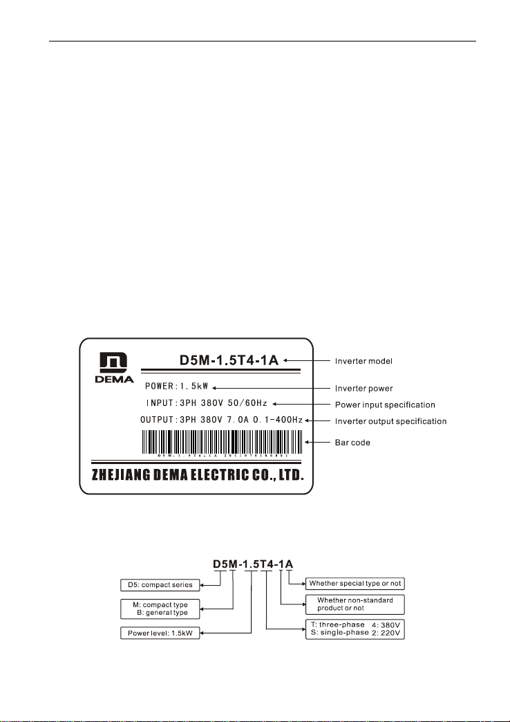
2. Introduction of D5M series nameplate
Figure 1-1 Introduction of D5M series ,D6B Series Nameplate
3. Model specification
Figure 1-2 Inverter Model Specification

NO.1 Safety Cautions
2
1.2 Installation
●Ambient temperature ranges from -5℃to 40℃, high temperature and moist shall be
prevented with the humidity less than 90% (non-condensation).
●Electromagnetic interference shall be prevented and interference source shall be kept
away.
●Water drop, steam, dust, cotton dust, and metal powder, as well as oil, salt and corrosive
gas shall be prevented entering.
●It is prohibited to install the inverter in environment with inflammable and explosive gas, as
well as liquid and solid.
●It is unallowable to install air switch, contactor, capacitor or piezoresistor concerned and
other devices at output side, so as to avoid inverter fault and damage to tripping protection or
components.
●The inverter shall adopt independent power supply rather than sharing power supply with
electric welder, so as to prevent the damage to inverter protection.
●To facilitate cooling and maintenance, the inverter shall be installed vertically with enough
space around to ensure ventilation.
●Installation wall shall be made of non-combustible materials like iron plate which shall be
prevented from vibration to cause damage to the inverter.
●If several inverters are installed up and down in one cabinet, certain spacing shall be kept
and baffle plate shall be set there between.
1.3 Use
1. Before energizing
●Voltage of the power supply selected must have the same specification with the input
voltage of inverter.
●PE refers to earthing terminal, please make sure the motor and inverter are grounded
properly to ensure safety.
●Do not set contactor between power supply and inverter to control startup or stop of inverter,
otherwise life time of the inverted will be impacted.
●Wiring of main circuit terminal shall be correct, L1.L2.L3 refer to power input terminals
which are prohibited to be mixed with U.V.W., otherwise, damage to the inverter may be
caused during energizing.
2. Energizing
●It is prohibited to plug and unplug the connector on inverter to prevent surge entering the
control panel and causing damage to the inverter.
●It is necessary to put the cover in place to prevent electric shock causing personal injury.
3. Running

NO.1 Safety Cautions
3
●It is prohibited to enable or disconnect motor unit during the running of inverter, so as to
prevent overcurrent tripping even burning the main circuit.
●It is prohibited to remove the front cover of inverter during energizing to prevent electric
shock causing personal injury.
●When the failure restart function is started, the motor will restart automatically after the
running stops; please keep away from the machine at this time to avoid accident.
●Stop switch will not be enabled until beingset, which is different from the emergency switch
in use, please pay attention to it.
1.4 Storage
●Temperature of the storage environment shall range from -20℃to +65℃;
●Relative humidity of the storage environment shall range from 0% to 95% in dry place
without condensation or dust;
●There shall be no corrosive gas and liquid in the storage environment, it shall be put on
shelter preferably with proper package;
●Long-term storage of inverter may cause deterioration of electrolytic capacitor, so it is
necessary to switch it on over 5h once a year at least, and the voltage must rise to rated
voltage value via a voltage regulator when inputting.
NO.2 Product Introduction
4
No.2 Product Introduction
2.1 Specification of D5M series
Model
Input voltage
Power
(KW)
Capacity of
driver (KVA)
Output
current (A)
Applicable
motor (KW)
D5M-0.4S2-1A
Single-phase 220V 50Hz
0.4
1.0
2.5
0.4
D5M-0.75S2-1A
Single-phase 220V 50Hz
0.75
2.0
5.0
0.75
D5M-1.5S2-1A
Single-phase 220V 50Hz
1.5
2.8
7.0
1.5
D5M-2.2S2-1A
Single-phase 220V 50Hz
2.2
4.4
11
2.2
D5M-3.7S2-1A
Single-phase 220V 50Hz
3.7
6.8
17
3.7
D5M-5.5S2-1A
Single-phase 220V 50Hz
5.5
10
25
5.5
D5M-0.4T4-1A
Three-phase 380V 50Hz
0.4
1.2
1.2
0.4
D5M-0.75T4-1A
Three-phase 380V 50Hz
0.75
2.2
2.7
0.75
D5M-1.5T4-1A
Three-phase 380V 50Hz
1.5
3.2
4.0
1.5
D5M-2.2T4-1A
Three-phase 380V 50Hz
2.2
4.0
5.0
2.2
D5M-3.7T4-1A
Three-phase 380V 50Hz
3.7
6.8
8.5
3.7
D5M-5.5T4-1A
Three-phase 380V 50Hz
5.5
10
12.5
5.5
D5M-7.5T4-1A
Three-phase 380V 50Hz
7.5
14
17.5
7.5
D5M-11T4-1A
Three-phase 380V 50Hz
11
19
24
11
D5M-15T4-1A
Three-phase 380V 50Hz
15
26
33
15
D5M-18.5T4-1A
Three-phase 380V 50Hz
18.5
32
40
18.5
2.2 General specification of the product
Name
D5M series
Control mode
V/F curve control
Input power
380V power: 380±15% 220V power:
220±15%
Four digital display and status
indicator
Display frequency, current, rotating speed,
voltage, counter, temperature, forward/reverse
NO.2 Product Introduction
5
status, fault, etc.
Communication control
RS-485
Operating temperature
-10~40℃
Humidity
Relative humidity ranging from 0 to 95% (without
condensation)
Vibration
Below 0.5G
Frequency
control
Range
0.10-400.00Hz
Accuracy
Digital type: 0.01% (-10-40℃); analog type: 0.1%
(25±10℃)
Setting resolution
Digital type: 0.01Hz; analog type: 1% of the
maximum operating frequency
Output resolution
0.01Hz
Keyboard setting
mode
Set as directly
Analog setting
mode
External voltage 0-5V, 0-10V, 4-20mA, 0-20mA.
Other functions
Three hopping frequencies (lower-frequency limit,
startup frequency and stop frequency) can be set
respectively
General
control
Acceleration/decele
ration control
4 optional acceleration/deceleration time (0.1-6500
seconds)
V/F curve
V/F curve can be set optionally
Torque control
Torque can be set rising with the maximum of
10.0%, and it can reach 150% when starting at
1.0Hz
Multi-function input
terminal
6-way programmable input; realize the functions
like 8-segment speed control, program running,
4-segment acceleration/deceleration switching,
UP, DOWN function, counter, external emergency
stop, etc.
Multi-function
output terminal
1-way programmable output; realize running, zero
speed, counter, external exception, program
running and other indications as well as alarm.
Other functions
Automatic voltage regulation (AVR), deceleration
stop or free stop, DC brake, automatic reset and
restart, frequency tracking, PLC program control,
transverse control, draft control, automatic
energy-saving running, carrier regulation (up to
20KHz), etc.

NO.2 Product Introduction
6
Protection
Function
Overload protection
Electric relay protection motor driver (constant
torque: 150% per minute, fans: 120% per minute).
FUSE protection
In case of fuse, the motor stops running
Over voltage
220V: DC voltage>390V 380V: DC
voltage>800V
Low voltage
220V: DC voltage<200V 380V: DC
voltage<400V
Restart after
transient stop
Restart after transient stop through frequency
tracking mode
Stall prevention
Stall prevention during acceleration/deceleration
Short circuit of
output terminal
Electronic circuit protection
Other functions
Overheating protection of radiating fin, reverse
limit, direct startup after operating, fault reset,
parameter locking, etc.
NO.3 Wiring
7
No.3 Wiring
3.1 Arrangement of main circuit terminals
L1
L2
L3
DC+
DB
U
V
W
[Note] Screws on main control board serve as PE terminals for that of 0.4-1.5kW.
3.2 Arrangement of control terminals
FA
FB
FC
X6
X5
X4
X3
X2
X1
GND
AI1
AI2
12V
A0
3.3 Description of main circuit terminals
Symbol of
terminal
Name of terminal
Description
L1.L2.L3
Input power terminal
Connected to three-phase 380V power
(single-phase 220V grade machine is
connected via terminals L1 and L2)
U.V.W
Inverter output terminal
Connected to three-phase motor.
DC+
DC output + terminal
DC bus output terminal is used for connecting
external brake unit or common DC bus
system. (DC- is not provided for partial
models)
DC-
DC output - terminal
DB
Brake output terminal
Connecting brake resistor between DB and
DC+.
PE
Earthing terminal
Inverter housing earthing terminal must be
earthed.

NO.3 Wiring
8
3.4 Description of control terminals
Symbol of
terminal
Function of terminal
Description
X1
Multi-function digital input
terminals 1-6
Set as forward during delivery
X2
Set as reverse during delivery
X3
Set as reset during delivery
X4
Set as high speed during delivery
X5
Set as medium speed during delivery
X6
Set as low speed during delivery
GND
Digital/analog/communication
and power earthing terminals
Isolation of GND inside from PE
12V
+12V power supply
Maximum output current: 150mA
AI1
Analog voltage input
Input voltage range: 0-+10V
AI2
Analog current/voltage input,
selecting via jumper1, default to
current input
Input current range: 0-+20mA
Input voltage range: 0-+10V
A0
Analog voltage output
Output voltage range: 0-+10V
FA、FB、FC
Multi-function relay output
FA-FC: normally open, FB-FC:
normally closed
Contact specification: 250VAC/3A,
30VDC/3A
RS+ RS-
RS485 communication interface
Available connection of 1-32 RS485
sites
3.5 Description of jumper function
No.
Function
Ex-factory setting
J1
Selection of AI2 input type
V: Voltage mode mA: Current mode
mA
J2
Selection of X1-X6 wiring mode
NPN type or PNP type
NPN
Wiring mode of multi-function digital input terminals X1-X6:
(1) When NPN type wiring mode is adopted for external equipment, leakage type logic is
induced and the current flows out from input terminal (sourcing current) as shown in Figure
3-1, at the same time parameter P067=0 is required.

NO.3 Wiring
9
[Note] NPN type wiring mode shall be adopted in case of P067=0.
Figure 3-1 NPN Type Wiring Mode
(2) When PNP type wiring mode is adopted for external equipment, source-type logic is
induced, and the current flows into from input terminal (sinking current) as shown in Figure
3-2, at the same time parameter P067=1 is required.
[Note] PNP type wiring mode shall be adopted in case of P067=1, at this time 9v
above at input terminal is high level.
Figure 3-2 PNP Type Wiring Mode

NO.3 Wiring
10
3.6 Basic wiring diagram
Inverter wiring involves main circuit and control circuit. The user can raise the cover of
housing, at this time main circuit terminal and control circuit terminal shall be viewed, and the
user must conduct correct connection as per wiring circuit below.
Figure 3-3 below refers to standard wiring diagram of ex-factory D5M series.
Figure 3-3 Standard Wiring of D5M series ,D6B series Inverter

NO.3 Wiring
11
1. Main circuit wiring
●During wiring, please select wire diameter specification and conduct wiring as per those
specified by electrical engineering laws so as to ensure the safety.
●For power supply wiring, prefer shielded wire or spool, and earth isolating layer or both
ends of spool.
●Be sure to install air circuit breaker NFB between the power and input terminal (L1.L2.L3).
(In case of applying leakage switch, please use the breaker with high frequency solution)
●Do not connect AC power to inverter output terminal (U.V.W).
●Prevent output wire touching metallic part of inverter housing; otherwise, earth short-circuit
may be induced.
●Do not apply phase-shifting capacitor, LC, RC noise filter or other elements to output end of
inverter.
●Indispensably make main circuit wiring of inverter away from other control equipment.
●When the wire between inverter and motor exceeds 15m (220V grade) or 30m (380V
grade), extremely high dV/dT shall emerge inside motor coil and it shall produce damage to
layer insulation of the motor, so it is necessary to useAC motor dedicated to inverter or install
reactor onto inverter side.
●In case of long distance between inverter and motor, reduce carrier frequency, for the
larger the carrier frequency is, the larger the higher harmonic leakage current becomes,
which shall produce adverse effect on the inverter and other equipment.
2. Control circuit wiring
●It is not allowed to place signal wire and main circuit wire inside the same slot.
●Supply cord of signal wire should be shielded wire with the size of 0.5-2.0mm.
●Control terminal on control board should be correctly used as required.
3. Earth wire
●Please properly earth terminal PE of earth wire.
220V grade: The third type earthing (earthing resistance is below 100)
380V grade: Particularly the third type earthing (earthing resistance is below 10)
●Use earth wire as per fundamental length and size specified by electrical equipment
technology.
●Absolutely avoid sharing earth electrode with welding machine, power generating machine
and other large-scale power equipment and make earth wire away from power line of
large-scale equipment as much as possible.
●Earth wire must be short to the utmost extent.
NO.4 Manipulator Description
12
No.4 Manipulator Description
4.1 Description of operation panel appearance and key function
Figure 4-1 D5M Series Digital Manipulator
[Note] Two switching modes of forward and reverse rotation are provided for D5M:
1) Press and hold down the key FOR/REV;
2) Press the key Program (PROG), then use the keys ▲and ▼to select; enter
parameter setting interface if pressing the key Program (PROG) again.
4.2 Description of indicator functions
Indicator
Function description
FOR
Motor forward
REV
Motor reverse
RUN
Motor is running
STOP
Motor is stopped
PRM
Display motor speed
NO.4 Manipulator Description
13
4.3 Description of displayed items
Displayed content
Description
Output frequency is 50.0Hz at this time
Set frequency is 50.0Hz
Output current is 3.0A at this time
Output speed is 1440r/min and speed light turns on at this time
DC voltage is 510V at this time
AC voltage is 380V at this time
Inverter temperature is 35.0℃at this time
Counter value is 105 at this time
PID target value is 50.0%
PID feedback value is 48.0%

NO.5 Function List
14
No.5 Function List
Description of special symbols:
* indicates that this parameter content has various set values or it shall be specifically set
based on actual situation.
Ex-factory value refers to parameter value set during delivery of inverter or parameter value
refreshed while the user restores ex-factory operation.
Alteration refers to alternative attribute of the parameter. ○indicates that the alteration is
available during shutdown and operating, ×indicates that the alteration is unavailable
during operating, and Δrefers to read-only parameter which cannot be altered by the user.
5.1 Basic function parameters
Function
code
Name of function
Setting range and data content
Ex-factory
value
Alteration
P000
Parameter locking
0: Invalid 1: Valid
0
╳
P001
Control mode
0: Manipulator
1: External terminal
2: Communication port
0
╳
P002
Frequency setting
selection
0: Manipulator
1: External terminal
2: Communication port
3: Manipulator potentiometer
0
╳
P003
Main frequency
0.00-400.00 Hz
*
○
P004
Reference
frequency
0.01-400.00 Hz
50.00
╳
P005
Maximum operating
frequency
10.00-400.00 Hz
50.00
╳
P006
Intermediate
frequency
0.01-400.00 Hz
2.5/3.0
╳
P007
Minimum frequency
0.01-20.00 Hz
0.50
╳
P008
Maximum voltage
0.1V-*
220/380
╳
P009
Intermediate voltage
0.1V-*
*
╳
P010
Low-frequency
torque boost voltage
0.1V-50.0V
*
╳
P011
Lower frequency
0.00-400.00 Hz
0
○

NO.5 Function List
15
limit
P012
Reserve
P013
Parameter resetting
8 restore ex-factory value
00
╳
P014
Acceleration time I
0.1-6500.0s
*
○
P015
Deceleration time I
0.1-6500.0s
*
○
P016
Acceleration time II
0.1-6500.0s
*
○
P017
Deceleration time II
0.1-6500.0s
*
○
P018
Acceleration time III
0.1-6500.0s
*
○
P019
Deceleration time III
0.1-6500.0s
*
○
P020
Acceleration time IV
0.1-6500.0s
*
○
P021
Deceleration time IV
0.1-6500.0s
*
○
P022
Reserve
5.2 Application function parameters
Function
code
Name of function
Setting range and data content
Ex-factory
value
Alteration
P023
Reverse prohibit
0: Reverse prohibit
1: Reverse allow
1
╳
P024
Stop key is valid or not
0: STOP invalid
1: STOP valid
1
╳
P025
Start mode
0: Start from starting frequency
1: Frequency tracking start
0
╳
P026
Stop mode
0: Decelerate stop
1: Free running stop
0
╳
P027
Starting frequency
0.10-30.0 Hz
0.5
╳
P028
Stop frequency
0.10-30.0 Hz
0.5
╳
P029
Start braking time
0.0-25.0s
0.0
╳
P030
Stop braking time
0.0-25.0s
0.0
╳
P031
DC braking level
0.0-20.0%
2.0
╳
P032
Frequency tracking
time
0.1-20.0s
5.0
╳
P033
Current tracking
frequency level
0-200%
150
╳
P034
Voltage rise time
during frequency
tracking
0 .1-10.0s
0.5
○
P035-P040
Reserve
P041
Carrier frequency
0-15
*
╳
NO.5 Function List
16
P042
Jogging frequency
0.00-400.00 Hz
5.00
○
P043
S curve time
0.0-6500.0s
0.0
○
5.3 Functional parameters of input/output terminals
Function
code
Function name
Setting range and data content
Ex-factory
value
Alteration
P044
FOR(X1) function
0: Invalid 1: Run 2: Forward
3: Reverse 4: Stop
5: Forward/reverse
6: Inching 7: Inching forward
8: Inching reverse
9: External control timer I
10: External control timer II
11: Setting frequency is forced
to P003
12: Radiator or motor
overheating
13: Emergency stop 14: Reset
15-16:Reserve
17: Acceleration/deceleration
time selection I
18: Acceleration/deceleration
time selection II
19: Multi-segment speed I
20: Multi-segment speed II
21: Multi-segment speed III
22: High speed
23:Medium speed
24: Low speed 25: PID
allowed
26: Multi-segment speed IV
27: UP 28:DOWN
29: Draft allowed 30: Reserve
31:Pulse counter
32: Pulse counter resets
02
╳
P045
REV(X2) function
03
╳
P046
RST(X3) function
14
╳
P047
SPH(X4) function
22
╳
P048
SPM(X5) function
23
╳
P049
SPL(X6) function
24
╳
P050
Y1 output function
0: Invalid
1: Indication during running
2: Zero-speed indication
3:Fault indication
01
○
P051
Y2 output function
05
○
P052
Output function (KA and
KC are terminals)
00
○
This manual suits for next models
16
Table of contents
Popular Inverter manuals by other brands

Goodwe
Goodwe GW9900-MS-30 Quick installation guide

Magnum Energy
Magnum Energy MagnaSine Hybrid owner's manual

Trannergy
Trannergy PVI 5400TL user manual

Stober
Stober POSYDYN SDS 4281 Supplementary Documentation

Power Electronics
Power Electronics SD 500 Series Hardware and installation manual

Perfect power systems
Perfect power systems WM.20A01OP manual


Magnum Dimensions
Magnum Dimensions CSW2012-X owner's manual

Stanley
Stanley Pc100 instruction manual

hpmont
hpmont HD31-4T2P2P user manual

Endress
Endress ESE Series Use and maintenance manual

CAC / BDP
CAC / BDP FOR BYPASS AND FAN POWERED HUMIDIFIERS owner's manual

Westerbeke
Westerbeke 10.0KW-60Hz Service manual