6
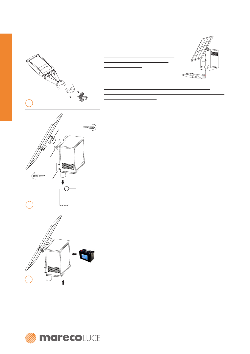
DEVA SOLAR
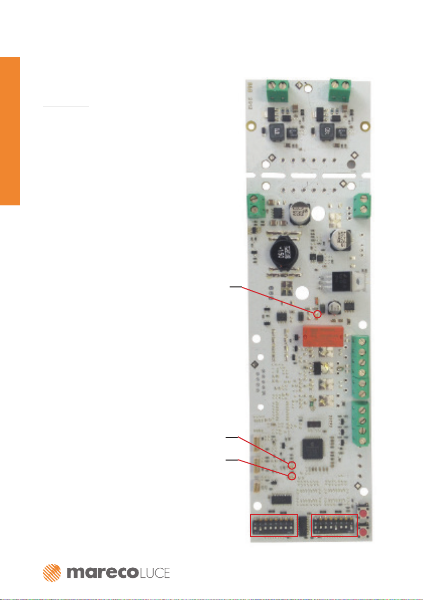
Electronic circuit board (ECB) Deva Solar
User's manual
Factory standard programming:
SMART MODE operating mode with on at sunset for 8 hours and a battery duration of 5 nights;
the luminosity for the grid connection is set at 100% and the time for the movement sensor is set to 2
minutes.
NORMAL
In this mode the luminosity of the LEDs is xed at a constant 50% (175mA). Everything is dependent on the
panel: if the battery is recharged with the same quantity of energy it consumed the previous night, then the
system is in energy balance and will guarantee light every night, otherwise, it will use the battery’s energy
reserve until it runs out (the battery will shut off when only 20% storage remains).
The possible running modes are:
- on at sunset for 8 hours
- on at sunset for 10 hours
- on at sunset for 4 hours, then shutting off internal LED ring and reducing outer ring to 50%, then 2 hours
before sunrise back to 100%*
- on from sunset to sunrise*
Grid connection: the switch over occurs when the battery is no longer capable of supplying the LEDs the
xed current (175mA). It is possible to set the dip switch for 100% and if/when the system connects to the
grid the LEDs run at 100% of their nominal power (350mA). A coloured
LED signals that the product is connected to the grid.
Movement se nsor: from sunset to sunrise the system will be on with the LEDs running at 25%, until the
sensor detects movement, from that moment the whole tting will be on at 100% (NORMAL mode); using the
dip switches it is possible to select the duration of the increased luminosity: 1,2, or 3 minutes.
SMART
In this mode the luminosity of the LEDs is variable. Priority is given to battery charge; this calculated each
night based on the energy transferred from the panel. The energy to be supplied to the LEDs is determined
based on an algorithm which is divided by the nightly duration and the operating mode (in this case SMART).
If the panel manages to recharge the battery with the same quantity of energy it consumed the previous night,
then the system is in energy balance and will guarantee light every night, otherwise, it will use the battery’s
energy reserve until it runs out (the battery will shut off when only 20% storage remains).
The possible running modes are:
- on at sunset for 8 hours
- on at sunset for 10 hours
- on at sunset for 4 hours, then shutting off internal LED ring and reducing outer ring to 50%, then 2 hours
before sunrise back to 100%*
- on from sunset to sunrise*
Grid connection: the switch over occurs when the battery is no longer capable of running the LEDs at 50%
luminosity. It is possible to set the dip switch for 100% and if/when the system connects to the grid the LEDs
run at 100% of their nominal power (350mA).
A coloured LED signals that the product is connected to the grid.
Movement sensor: from sunset to sunrise the system will be on with the LEDs running at 25%, until the
sensor detects movement, from that moment the whole tting will be on at full luminosity. Using the dip
switches it is possible to select the duration of the increased luminosity: 1,2, or 3 minutes.
*The running modes “sunset to sunrise” and “4hrs from sunset – 2hrs from sunrise” will be operative after
3 days and 3 nights; before this time has passed the system will function for “8hrs from sunset”.