Page 9
12/23/08
DKY
DATE
DATE
4010 320TH ST. PO BOX 189
BOYDEN, IOWA 51234
THE DRAWING AND ALL
INFORMATION THERE
ON ARE THE PROPERTY OF
DEMCO
TOLERANCES
pp2manclutch
DRAWN BY
ENG APPOV.
DESCRIPTION
DRAWING. NO.
REV
SCALE: 1:8
SHEET 1 OF 1
_
DOUBLE PISTON PUMP W/ CLUTCH
.X =
.060 MIN. MACHINE SURFACE 250
.XX = ±.030 BREAK ALL SHARP EDGES
.XXX = ±.010 BEND AND DRAFT
±1°
UNLESS OTHERWISE
SPECIFIEDALL DIMENSIONS
ARE IN INCHES
THIRD ANGLE
PROJECTION
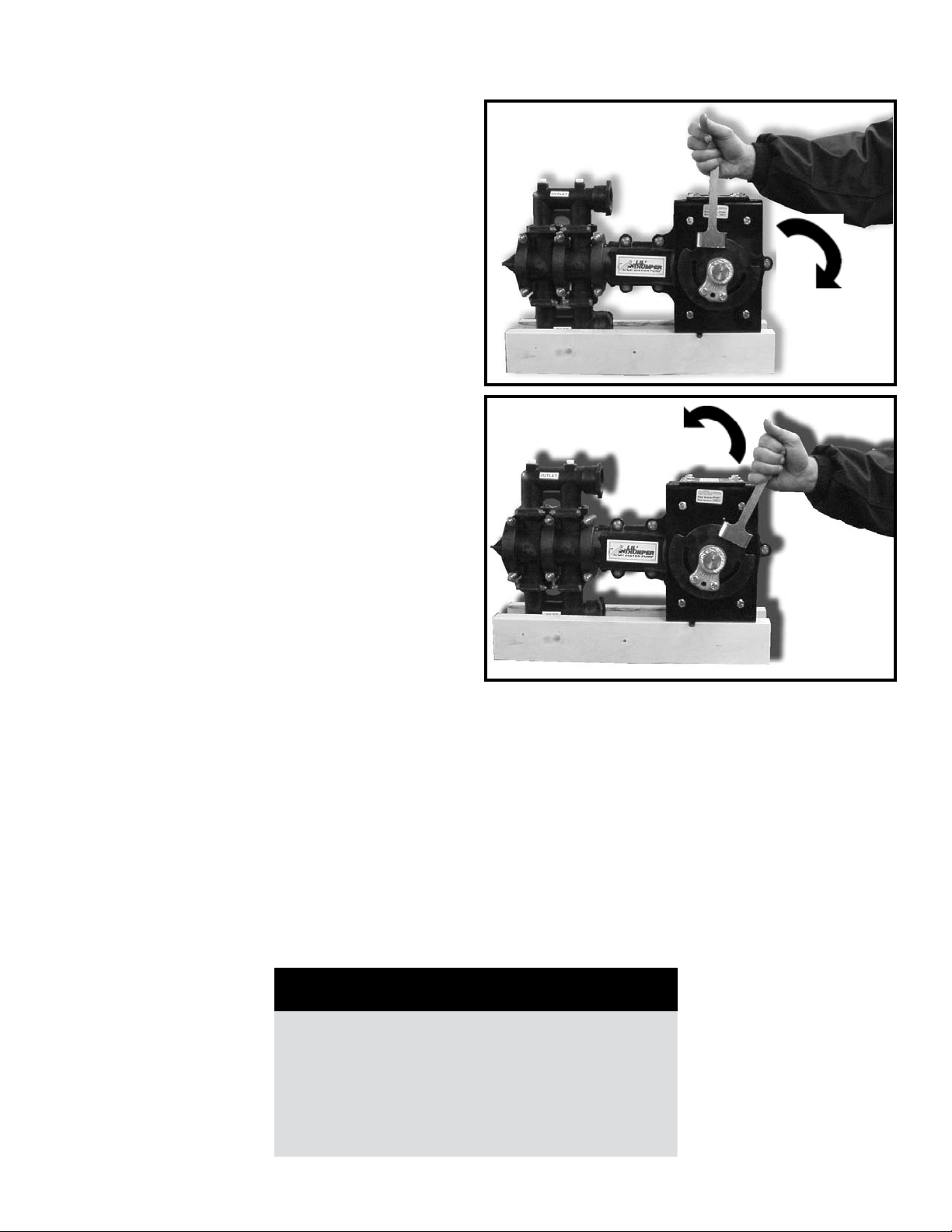
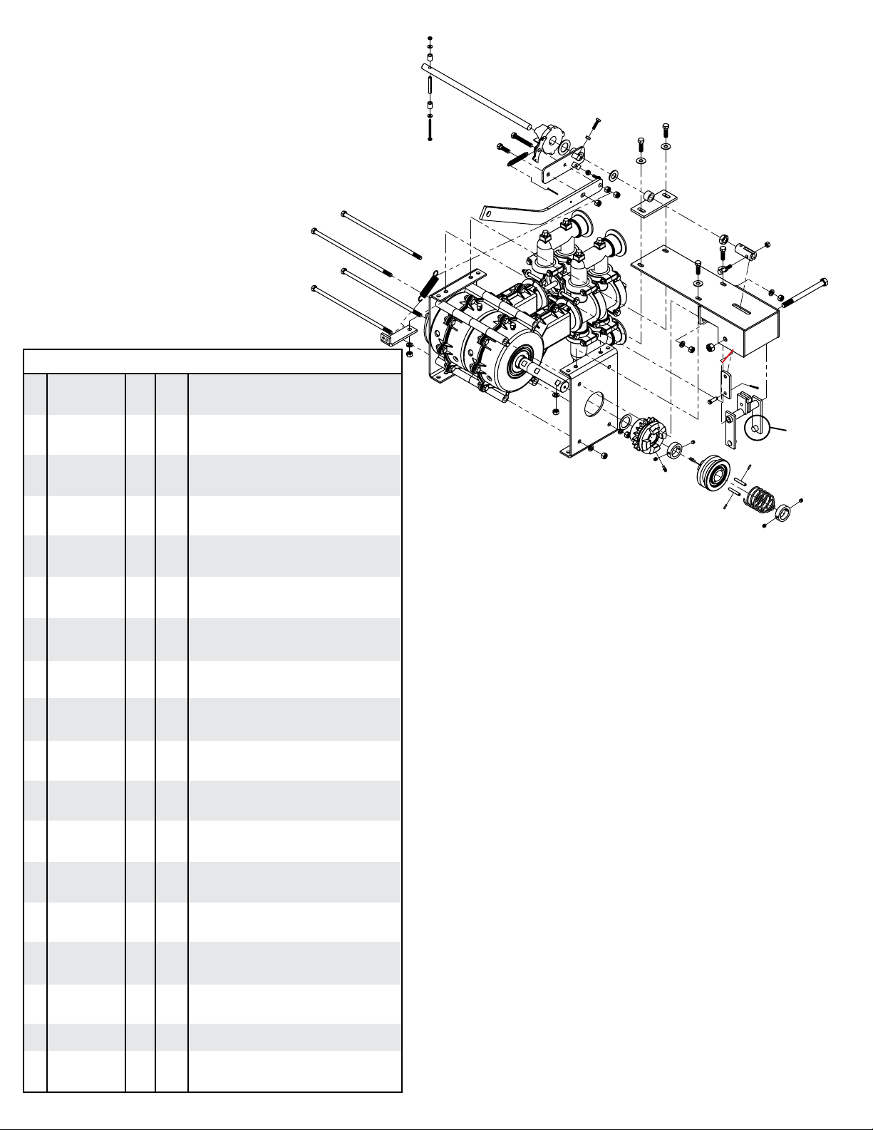
MANUAL CLUTCH PARTS
BREAKDOWN
REF. PART QTY.
NO. NO. PP1 PP2 DESCRIPTION
1
1
1
24
26
29
46
40
15
43
33
23
34
35
38 15
16
16
37
37
45
41 1
42
44
18
13 A
10
11
9
9
87
2
16
5
53
2
11
10
4
4
31
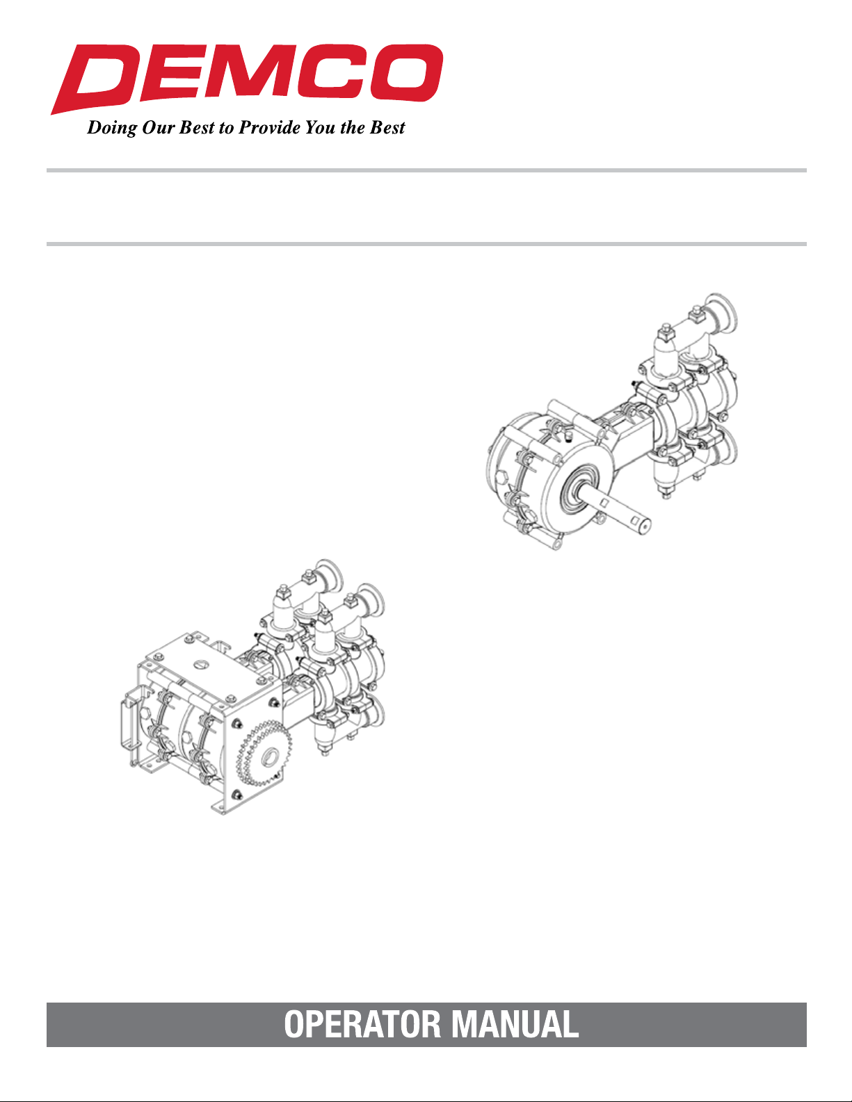
Bolt the throw out arm bracket (#40) and arm assembly (preas-
sembled at factory) to the top of the pump using two 3/8” bolts.
The 1-1/2” long bolt should be used to attach the return spring
bracket (#20). Connect the return spring (#21) and remove
any remaining shipping tape from the assembly. Loosen set
screw (#1) in clutch throw out shaft connector (#42). Turn
connector, not the shaft, until holes align for the 5/16” x 1-1/2”
bolt (#44) to pass through connector and Yoke (#14). Lock
connector in place by tightening jam nut (#41). Grease the
zerk in the throw out ratchet casting (#33) before using the
pump and as needed thereafter. An occasional drop of oil to
the other moving parts of the clutch will prevent unnecessary
wear. Check to make sure the clutch completely disengages.
The sprocket casting should turn freely. The handle should
return to engage the next cog in the throw out ratchet casting
when the clutch is tripped.
Important: Make sure the clutch throw out yoke pegs fit
loosely in the groove in the clutch yoke casting when the
clutch is engaged.
Attach the pull rope to the eye in the throw out handle to permit
operation of clutch from the tractor cab. To change the direc-
tion of pull for the clutch handle, simply remove the handle
and install it in the opposite position. Then re-hook the throw
out pawl spring in the other hole in the throw out pawl and
move the spring return bracket to the other side of the handle
assembly and re-hook the return spring. Make sure the pawl
works freely on the side of the throw out arm plate.
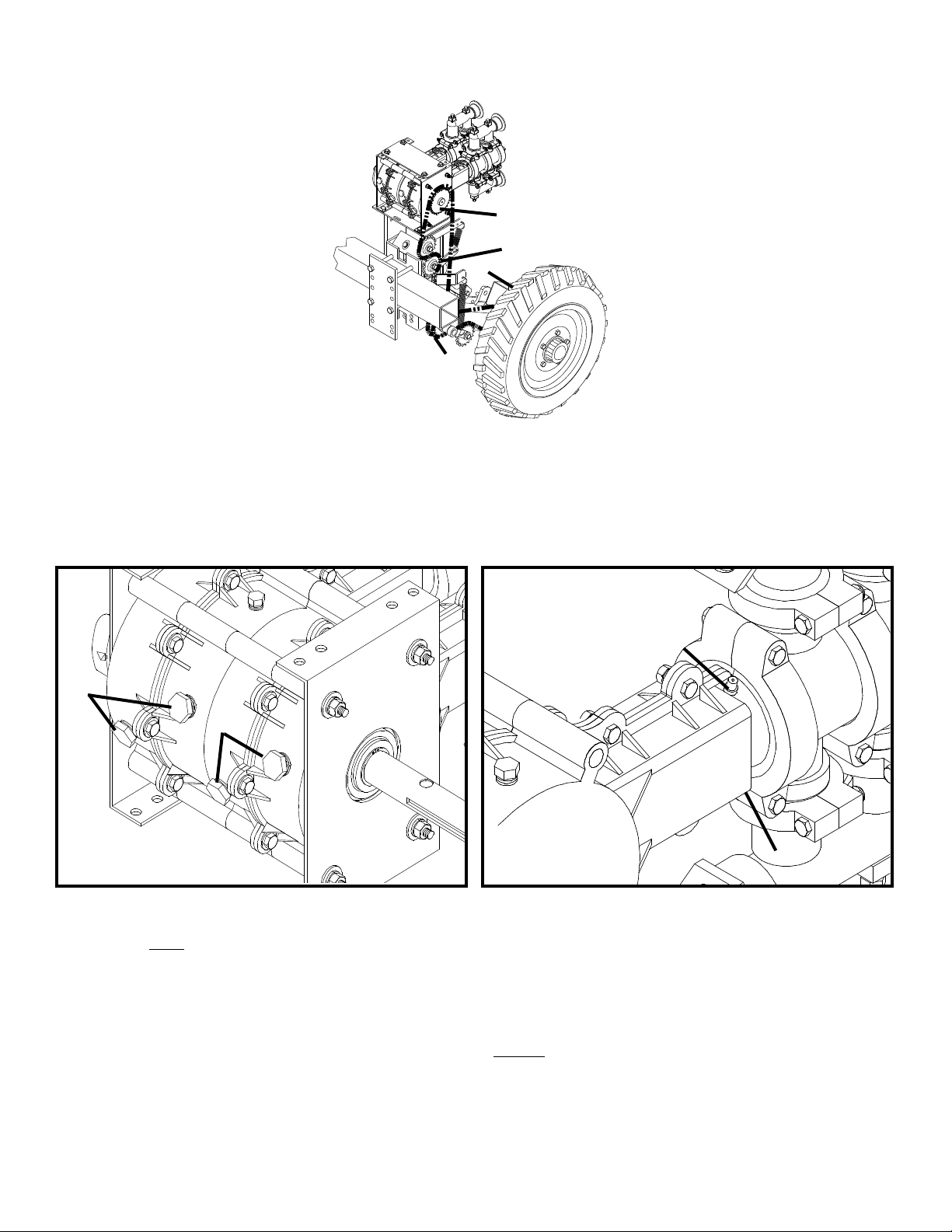
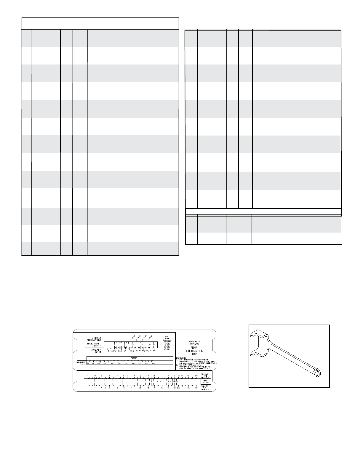
ADJUSTMENT INSTRUCTIONS
YOKE
PEG
16
28
25
26
27
25
10
17
15
16
10
11
14
10
11
12
20
21
19
22
36
32
30
NOTE: Clutch Throw out Yoke must be positioned as
shown, with block “A” facing the pump.
45 45
45
1. 00087 5 5 5/16” x 5/16” Cup Point Set Screw
2. 01598-95 2 2 1-1/4” I.D. Lock Collar
3. 01193 1 1 Clutch Spring
4. 01976 2 2 1/8” x 1/2” Roll Pin
5. 01549 2 2 1/4” x 1/4” x 1-5/8” Key
6. 01184 1 1/4-30 1 1 1-1/4” I.D. Clutch Yoke
7. 01183 1 1/4-30 1 1 1-1/4” I.D. Sprocket Casting (18 tooth)
8. 01979 1 1 1-1/4” I.D. 18 Ga. Machine Washer
9. 01498-30 2 2 Pump Side Plate
10. 00061 9 9 3/8”-16UNC Hex Nut
11. 00060 8 8 3/8” Lockwasher
12. 02056 - 2 3/8”-16UNC x 11-1/2” Hex Head Bolt
12. 00613 2 - 3/8”-16UNC x 6” Hex Head Bolt Gr. 5
13. 00173 1 1 1/2”-13UNC Locknut
14. 01576-30 1 1 Clutch Throw Out Yoke
15. 00059 4 4 3/8” Flatwasher
16. 00523 5 5 3/8”-16UNC x 1.25” Hex Head Bolt Gr. 5
17. 00349 1 1 1/2”-13UNC x 6” Hex Head Bolt Gr. 5
18. 01525-30 1 - Piston Pump Top Bracket
18. 01526-30 - 1 Piston Pump Top Bracket
19. 02057 - 2 3/8”-16UNC x 12” Hex Head Bolt
19. 04219 2 - 3/8”-16UNC x 6-1/2” Hex Head Bolt Gr. 5
20. 01527-30 1 1 Throw Out Arm Return Spring Bracket
21. 01547 1 1 Throw Out Arm Return Spring
22. 01211-30 1 1 Throw Out Arm Extension Handle
23. 01982 1 1 3/32” x 1-1/4” Cotter Key
24. 01983 1 1 #10 x 2-1/2” Round Head Stove Bolt
25. 07490 2 2 3/16” Flatwasher
26. 01212-95 2 2 Throw Out Roller
27. 01985 1 1 5/16” x 2” Roll Pin
28. 01986 1 1 #10 Nut
29. 01214-95 1 - Throw Out Shaft
29. 01565-95 - 1 Throw Out Shaft
30. 01548 1 1 Throw Out Pawl Spring
31. 01987 1 1 3/8”-16UNC x 2-1/2”FullThread Hex Head Bolt
32. 01185 1 1 Throw Out Pawl
33. 01186-30 1 1 Throw Out Pawl Ratchet Casting
34. 00062 2 2 1/4”-20UNC Hex Nut
35. 04055 2 2 1/4”-20UNC x 1” Hex Head bolt
36. 01213-30 1 1 Throw Out Arm Plate
37. 02592 2 2 3/8”-16UNC Nylon Insert Locknut
38. 00496 1 1 5/8” Machine Washer
39. 00914 1 1 3/8”-16UNC x 1-1/2” Hex Head Bolt Gr.5
40. 01216-30 1 1 Throw Out Arm Bracket
41. 00489 1 1 5/8”-11UNC Jam Nut
42. 01215-95 1 1 Clutch Throw Out Shaft Yoke Connector
43. 02802 1 1 5/16”-18UNC Nylon Insert Locknut
44. 00372 1 1 5/16”-18UNC x 1-1/2” Hex Bolt Gr. 5
45. 05023 4 4 3/16”Grease Zerk
46. 05587 1 1 1.00”X 14GA Machine Washer
47. 01575-30 1 1 Top Pivot Yoke Link
48. 02528 1 1 Clevis Pin
49. 00009 1 1 1/8” Cotter Pin
47
48
49