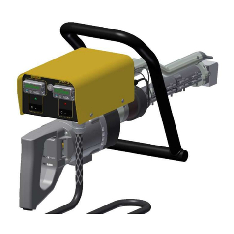
Demtech Pro-X 600-0100/A Pro-X 600-0100/PRT/A User manual

Pro-X
Operator’s Manual
Model Numbers: 600-0100/A
600-0100/PRT/A
Revision: D

Rev. D, April 2021
Pageii Pro-XOperator’sManual
© Copyright 2021 by DEMTECH Services, Inc.
All Rights Reserved
Scope of Manual:
This manual contains procedures for safety, general unpacking,
set-up, and operation of your DEMTECH Services, Inc. Pro-X Extrusion Welder.
The text of this publication, or any part thereof, may not be reproduced or transmitted in any
form or by any means, electronic or mechanical, including photocopying, recording, storage in
an information retrieval system, or otherwise, without prior written permission of DEMTECH
Services, Inc.
Notice
Patents have been granted and/or patent applications are pending or are in the process of
preparation on all DEMTECH Services, Inc. developments.
The material in the manual is for informational purposes only and is subject to change without
notice.
DEMTECH Services, Inc. assumes no responsibility for any errors that may appear in this
manual.
Manual Number: 600-OPERATOR’S MANUAL/PRO-X, Revision: D
DEMTECH Services, Inc.
6414 Capitol Avenue Diamond Springs, CA 95619 U.S.A.
Telephone: (530) 621-3200
Toll Free: (888) 324-9353
Fax: (530) 621-0150
Web Site: www.demtech.com

Rev. D, April 2021
Pro-X Operator’s Manual Page iii
Table of Contents
1
SAFETY PRECAUTIONS………………………………………………….PAGE 1
2
GENERAL SAFETY & MAINTENANCE INFORMATION…………...PAGE 2
2.1
Intended Use………………………………………………………...Page 2
2.2
Maintenance………………………………………………………...Page 2
3
GENERAL PRODUCT DATA…………………………………………….PAGE 3
4
OPERATING ENVIRONMENT…………………………………………..PAGE 3
5
SITE PREPARATION……………………………………………………...PAGE 3
6
UNPACKING & INSTALLATION INSTRUCTIONS…………………..PAGE 4
6.1
Unpacking and Preparation…………………………………………Page 4
6.2
Electrical Plug Connection………………………………………….Page 5
6.3
Generator Recommendations……………………………………….Page 7
7
WELDER CONTROLS…………………………………………………….PAGE 8
7.1
Recommended Temperature Settings……………………………….Page 9
7.2
Setting Pre-Heat Temperature………………………………………Page 9
7.3
Setting Plastic Heat Temperature…………………………………...Page 9
7.4
Shut-Down Procedure……………………………………………..Page 10
8
WELDER SET-UP & OPERATION…………………………………….PAGE 11
8.1
Set-Up Preparation………………………………………………...Page 11
8.2
Start a Weld………………………………………………………..Page 13
8.3
During a Weld……………………………………………………..Page 14

Rev. D, April 2021
Pageiv Pro-XOperator’sManual
8.4
Stop a Weld………………………………………………………….Page 14
8.5
Between Welds………………………………………………………Page 14
8.6
Checking the Output Temperature…………………………………...Page 15
8.7
Changing the Welding Shoe………………………………………….Page 16
9
FACTORY SERVICING…………………………………………………….PAGE 18
10
WELDER WIRING DIAGRAM……………………………………………PAGE 18
11
WELDER PRODUCT WARRANTY……………………………………….PAGE 18
11.1
600-0100/A/WD – PRO-X WIRING DIAGRAM (Parts ID)………Page 19
11.2
600-0100/A/WD – PRO-X WIRING DIAGRAM (Parts List)……..Page 20

Rev. D, April 2021
Page1 Pro-XOperator’sManual
1Safety Precautions
Safety precautions for operating personnel and equipment:
WARNING 1: Operating personnel should perform only the procedures described and
recommended in this manual. Only qualified service personnel familiar with electrical
shock hazards and mechanical entanglement hazards present inside the equipment should
perform disassembly or corrective maintenance of the equipment.
WARNING 2: To avoid shock hazards, the equipment must be grounded with an adequate
earth ground in accordance with local and national electrical codes.
WARNING 3: The locations of potentially dangerous voltages and other hazards are
identified and labeled on the equipment. Be careful to observe these warnings when installing,
operating, maintaining or servicing the equipment. Observe all warnings in this manual.
WARNING 4: Make sure to turn off the equipment power and remove the ~ (AC) line cord
from the power outlet before attempting to service the equipment. Do not perform service
unless you are qualified and trained to do so.
WARNING 5: This product is intended for operator attended operation only. This product
should never be left unattended at any time while it is plugged in and the power is turned on.
Incorrect use of the product such as overheating of the material can present a fire and explosion
hazard, especially near combustible materials and explosive gases.
WARNING 6: This product is intended for operation in dry environments only. Higher
humidity environments should be kept non-condensing by avoiding large temperature swings.
WARNING 7: Do not touch the main housing, air nozzle and/or output molten material when
they are hot as they can cause burns. After use allow sufficient time for the product to cool to
room temperature before handling and stowing. Do not point or direct the hot air flow and the
output molten material in the direction of personnel.
CAUTION 1: Observe the precautions given on the equipment and within this manual to
prevent damage to the equipment.
CAUTION 2: Before connecting the equipment to its electrical power source, check that the
~ (AC) voltage, frequency and current to be supplied to the equipment are correct and
match the serial plate affixed to the system.
CAUTION 3: Use proper handling and packaging procedures for Electro-Static Discharge
(ESD) sensitive Printed Circuit Boards (PCB’s). Assume that all PCB’s are sensitive to
potential damage from ESD.
CAUTION 4: Unauthorized personnel should not remove from the equipment those panels or
covers that are provided for protection and/or require a tool to remove.

Rev. D, April 2021
Pro-XOperator’sManual Page2
2General Safety & Maintenance Information
The DEMTECH Services, Inc. Pro-X
TM
Thermoplastic Extrusion Welder, hereinafter
referred to as the Pro-X or welder, is a high temperature and voltage piece of equipment.
Always disconnect the power source before performing any service and/or maintenance
procedures on the welder. Never lift, pull or carry the welder by the power cord or
electrical connection. Always maintain slack in any extension cords connected to the
welder while in operation to avoid damage to the power connections. At all times while
operating the welder keep hands, fingers and other body parts well clear of the heating
element and related mounting components. Always use the Pro-X in a well-ventilated area
when welding materials such as PVC which can produce toxic fumes. Do not inhale toxic
fumes when present. Do not operate near flammable materials of any kind. Do not apply
flammable materials, including liquids, to seam area. Allow welder to cool to room
temperature, at least 15 minutes, before returning to the shipping/storage case. Protect
welder from exposure to rain or standing water. Never attempt to weld in standing water.
2.1
Intended Use
The Pro-X is intended as professional use equipment and is not intended for sale to the
general public. The total input power of the Pro-X is specified as greater than
1 kW although in lightly loaded conditions the actual power may be less than 1 kW.
The Pro-X has been manufactured utilizing the latest technology and current safety
standards and regulations. However, improper use or abuse may lead to hazardous
conditions for the user or other personnel or cause damage to the welder.
Always keep this manual with the welder at or near the location where the Pro-X is being
used so that it can be referred to quickly and easily.
The technician assigned to operate this welder must have read through and become
familiar with this manual, particularly all safety information, before operating the Pro-X.
No changes and/or modifications shall be made to the Pro-X especially as it relates to
safety.
2.2
Maintenance
Maintenance, inspection and adjustment of the Pro-X shall only be carried out by
qualified personnel. Before removing or installing spare parts or performing other repair
operations to the welder, consult DEMTECH Services, Inc. or your authorized
DEMTECH service center for advice on proper procedures. This will help insure a safe
and successful outcome. Always make sure all screw connections are tight before
attempting to operate the welder after maintenance and/or repair procedures. Also make
sure all covers, guards, and other safety devices have been fully reinstalled before use.

Rev. D, April 2021
Page3 Pro-XOperator’sManual
3General Product Data
The DEMTECH Services, Inc. Pro-X Thermoplastic Extrusion Welder, hereinafter
referred to as the Pro-X or welder, dramatically speeds the welding of plastic sheet
materials utilizing molten plastic. This function, combined with its simple construction
and easy-to-use controls, makes performing welding tasks very efficient. With minimal
setup, the welder speeds up processing time while providing a very rugged and reliable
welder. You can be assured that the Pro-X has been built using the highest quality materials
available which include billet aluminum and ground and hardened steel. DEMTECH
Services, Inc. strives to make our welders easy to use and built to last. Just like all other
DEMTECH Services, Inc. products, even a first-time user will be productive in minutes.
4Operating Environment
The Pro-X is intended to be operated within the following environmental ranges and
conditions. Operating the welder in environments which are less than or greater than the
nominal values listed can adversely affect performance.
Temperature ...............+32 to +100° Fahrenheit (F); 74° F Nominal
....................................(+0 to +38° Centigrade (C); 23°C Nominal)
Humidity ....................0 to 90% (non-condensing); 45% Nominal
Elevation ....................0 to 7,000 Feet; 2,000 Feet Nom
....................................(0 to 2,134 meters; 610 meters Nominal)
5Site Preparation
Before proceeding with the unpacking and installation instructions in the following
section(s) make sure the work site is prepared and ready to use the Pro-X. You should
have an adequate power source capable of providing clean Alternating Current (AC) power
at 220-240 Volts at the rated current. Refer to the welder serial plate affixed to the front
side of the controller housing for the voltage and current requirements of your welder. The
install and use area should be clean, dry and free of debris and provide adequate working
area to allow efficient and effective use of the welder.
Carefully follow the detailed unpacking and installation instructions provided in this
manual.

Rev. D, April 2021
Pro-XOperator’sManual Page4
6Unpacking & Installation Instructions
This section contains instructions for the unpacking, placement and installation of the Pro-
X. Carefully review the following information, sub-sections and each procedure before
beginning unpacking and installation of the welder.
The Pro-X comes complete in a sturdy, reusable, portable shipping/storage case. The
custom foam inserts protect the welder from damage during shipping and storage and
should always be left inside the case. When the welder is out of the case, make sure to
keep the lid closed to avoid dirt, dust, debris and/or water from getting inside. The welder
must be removed from the case and placed onto the work site for use. When not in use,
the Pro-X should always be stored in the shipping/storage case to protect it from the
elements and potential damage.
Note: The welder illustrated in this manual shows ALL available features for the
Pro-X, therefore, your welder may vary slightly in appearance from that depicted.
6.1
Unpacking and Preparation
a. Before opening the shipping/storage case for the first time and unpacking the welder,
inspect the outside of the case thoroughly for any signs of mishandling or damage
during shipping. Report any damage to the shipping carrier immediately and do not
proceed with unpacking. You should consult your administration concerning claims
for shipping damage. Please notify DEMTECH Services, Inc. or your authorized
DEMTECH distributor where the product was purchased in the event of any shipping
damage.
b. Unlatch and open the shipping/storage case lid and inspect inside the case and the
welder thoroughly for any signs of mishandling or damage during shipping. Report
any damage to the shipping carrier immediately and do not proceed with unpacking.
You should consult your administration concerning claims for shipping damage.
Please notify DEMTECH Services, Inc. or your authorized DEMTECH distributor
where the product was purchased in the event of any shipping damage.
c. Make note of the orientation of the welder and packing foam inserts inside the shipping
case to facilitate repackaging the welder after use.
d. To avoid injury to personnel and/or damage to the welder, be sure to use adequate care
when lifting and removing or lowering and replacing the welder into the
shipping/storage case.

Rev. D, April 2021
Page5 Pro-XOperator’sManual
e. The welder must be removed from the shipping/storage case and placed in an
appropriate location suitable for the welding you intend to perform.
6.2
Electrical Plug Connection
a. The Pro-X is supplied with a power cord, which is permanently connected to the bottom
side of the controller housing. Depending on the intended country of use, the plug at
the other end of the power cord will vary but, in all cases, must be rated for the voltage
and current requirements of the welder. It is highly recommended to use a twist-lock
or twist-to-connect type plug with a permanent ground connection. Refer to the welder
serial plate affixed to the front of the controller housing for the voltage and current
requirements of the welder. Install the power cord plug into an appropriate electrical
outlet supplying the proper ~(AC) power. In all cases the connection should only be
made to a circuit with a maximum 20A breaker rating.
b. Verify basic operation of the Pro-X before proceeding with the remainder of the
installation. The welder main power rocker switch is white and is located on the front
of the controller housing (see Figure 6.1). Toggle the switch to "I" to turn ON the
welder. Toggle the switch to "O" to turn OFF the welder.
Figure 6.1

Rev. D, April 2021
Pro-XOperator’sManual Page6
c. Turn ON the welder. The two temperature controller displays should turn on. Use
caution because depending on welder configuration the pre-heat blower motor may
start and hot air may exit the pre-heat nozzle. Use caution as the exhaust air can be
very hot. This procedure verifies the Pro-X is receiving suitable power and the welder
is functioning properly. If the displays power-up as described you are now ready to
operate the welder. If the welder does not power-up as described please contact
DEMTECH Services, Inc. or your authorized DEMTECH service center.
d. The operating voltage requirement for the Pro-X is 220-240 Volts ~ (AC) only. This
operating voltage range refers to the actual voltage as measured at the welder power
cord plug after any extension cords while operating the welder under load. The
following procedure should only be performed by a qualified electrician. To measure
the voltage under load, connect the welder to any extension cord(s) to be used and the
proper ~ (AC) source which may be an in-field generator supplying the power. If
applicable, start the generator then turn the welder power switch to the ON position.
Turn on the “Pre-Heat” and “Plastic Heat” heaters. Wait for the “Ready to Run” timer
to expire. Power the drill motor utilizing the trigger switch. Next, carefully separate
the plug at the end of the welder power cord just enough to expose the prongs but
without disconnecting the power. Using a digital volt meter measure the voltage under
load between the prongs. The measured value must be between 220 and 240 Volts ~
(AC).
Electrical Extension Cords
The Pro-X is capable of welding very long seams. This ability may warrant the use of
electrical extension cords. It is imperative to consider the length and wire gauge of any
extension cord used, as these factors will ultimately determine the actual welder operating
voltage. Extension cords should be a minimum of 12 gauge and regardless of overall length
should have a minimum number of plug connections. Table 6.2 lists extension cord gauge
and length recommendations.
Conductor Size
3-Wire
10 AWG
(5.3 mm
2
)
3-Wire
12 AWG
(3.3 mm
2
)
Length 500 Feet
(152 meters)
250 Feet
(76 meters)
Table 6.2 Maximum recommended extension cord lengths.

Rev. D, April 2021
Page7 Pro-XOperator’sManual
6.3
Generator Recommendations
When operating the Pro-X using house power from a building circuit use the appropriate
plug and power cord configuration. When in-field generators are used they must be rated
for a minimum of 5,000 watts, however a rating of 6,500 watts or more is highly
recommended in order to obtain the best welder performance and temperature control. As
a rule, higher wattage generators provide better welder performance. Keep in mind that
the length and wire gauge of any extension cord being used combined with the capacity of
the generator ultimately determines the operating voltage and therefore welder
performance.

Rev. D, April 2021
Pro-XOperator’sManual Page8
7Welder Controls
The Pro-X utilizes two temperature controllers located on the main control panel. The
upper controller operates the Pre-Heat (Air) temperature, and the lower controller operates
the Plastic Heat (Barrel/molten rod) temperature (see Figure 7.1).
Figure 7.1

Rev. D, April 2021
Page9 Pro-XOperator’sManual
7.1
Recommended Temperature Settings
Pre-Heat and Plastic Heat temperature settings will vary due to the wide range of variables
that can be experienced in the field. For example, ambient temperature, sheet material
type, temperature and thickness, wind conditions and other factors are all variables that
impact the appropriate temperature settings. These factors make it impractical to create a
chart that can universally cover all these varying conditions: Therefore, we recommend
contacting DEMTECH Services, Inc. or your authorized DEMTECH distributor where the
product was purchased to receive guidance for appropriate settings.
7.2
Setting Pre-Heat Temperature
The upper temperature controller regulates the Pre-Heat temperature. The current Pre-Heat
temperature set point is displayed on the smaller green digits to the right of the controller
display. The actual Pre-Heat temperature is displayed on the larger green digits to the left
of the controller display. To adjust the set point, press the up or down arrow buttons. Once
the set point has been adjusted to the desired temperature, allow approximately five
minutes for the Pre-Heat temperature to rise or fall and stabilize at the new set point.
7.3
Setting Plastic Heat Temperature
The right temperature controller regulates the Plastic Heat temperature. The current Plastic
Heat temperature set point is displayed on the smaller green digits to the right of the
controller display. The actual Plastic Heat temperature is displayed on the larger green
digits to the left of the controller display. To adjust the set point, press the up or down
arrow buttons. Once the set point has been adjusted to the desired temperature, allow
approximately five minutes for the welder Barrel temperature to rise or fall and stabilize at
the new set point before attempting to feed welding rod. The Pro-X is equipped with
electronic cold start protection, which prevents activation of the drill motor until a proper
operating temperature has been reached. Feeding welding rod before the welder Barrel
temperature has reached set point can cause damage to the drive motor unit.

Rev. D, April 2021
Pro-XOperator’sManual Page10
7.4
Shut-Down Procedure
When all welding operations are complete perform the following procedure to shut-down the
Pro-X and ready it for storage.
1. Start the drive motor to cause one or two inches of extrudate to be pumped out
of the Welding Shoe exit orifice.
2. Stop the drive motor and allow the extrudate hanging from the exit orifice to cool
for several minutes.
3. Cut the welding rod approximately 6-12 inches back from the Feed Port leaving
the rod protruding from the Feed Port.
4. Once the extrudate hanging from the Welding Show exit orifice has cooled, use
a pair of pliers with insulated handles to pull it from the end of the welder in a
twisting motion. This removes all material remaining in the Welding Shoe
Assembly area and prevents a “cold plug” from causing problems on next start-up.
Turn OFF the Pre-Heat heater toggle switch located on the back of the green Pre-Heat blower
housing by switching to the “O” (OFF) position. Allow the blower to run for several minutes
or until the temperature displayed on the Pre-Heat controller display is at 200 °F or below then
turn OFF the Pre-Heat blower toggle switch located on the controller main panel.
Unplug the Pro-X AC power cord and allow the welder to cool for at least fifteen (15) minutes.
Once safely cooled place the welder into the shipping/storage case.

Rev. D, April 2021
Page11 Pro-XOperator’sManual
8Welder Set-Up & Operation
The initial set-up of the Pro-X is by far the most critical aspect for proper welder operation.
Proper set-up not only leads to quality welding results but also minimizes wear and tear on
the welder itself. Improper adjusting of the welder can result in excessive wear on critical
components.
8.1
Set-Up Preparation
The procedures described in the following sections cover the initial set-up required for
welding. Initial operations must be made while the welder is at room temperature.
Install the desired welding shoe onto the end of the welder and orient the shoe and pre-heat
shield as necessary for the welding to be performed (refer to Section 8.7).
Adjust the grip handle to the best position for the welding to be performed (see Figure 8.1).
Loosen the handle by gripping it and twisting counter-clockwise. This will loosen the
handle clamp. Position the handle within its 180° swing and tighten the handle clamp by
twisting the handle clockwise.

Rev. D, April 2021
Pro-XOperator’sManual Page12
Figure 8.1
The welder contains a cold start protection feature that prevents operation of the drill
motor before the welder has reached the proper operating temperature. To prepare the
welder for operation set the Pre-Heat and Plastic Heat temperatures. These settings will
vary depending on the material to be welded and the ambient environment. Operating
experience will dictate the proper setting. Once set turn ON the Pre-Heat and Plastic Heat
by switching the toggle switches on the welder front panel.

Rev. D, April 2021
Page13 Pro-XOperator’sManual
8.2
Start a Weld
Once the welder has stabilized at the operating temperature insert the end of the welding
rod into the feed port while simultaneously powering the drill motor (see Figure 8.2). Once
the welding rod starts to feed it will continue to self-feed as you weld. The welder drill
motor should only be operated when welding rod is being continuously fed into the welder
and should never be run dry. Direct the pre-heat nozzle toward the area to be welded. Pre-
warm the welding zone with back-and-forth movements of the welder tip. Position the
welder on the prepared welding zone and operate the drill motor trigger switch.
Figure 8.2
WeldingRodFeedPort

Rev. D, April 2021
Pro-XOperator’sManual Page14
8.3
During a Weld
Keep the welding rod being fed into the welder clean and dry. Foreign material such as
dust, dirt, sand and water droplets introduced into the feed port can cause premature wear
to the welder.
For long welds the Pro-X drill motor has a locking pin which allows you to lock the drill
motor trigger switch in the ON position.
Further adjustments of the Pre-Heat and Plastic Heat temperatures may be required.
8.4
Stop a Weld
To stop welding either release the drill motor trigger or if trigger is locked “ON” pull and
release trigger to stop.
If there is going to be a short pause before the next weld, clear the excess molten plastic
(refer to Section 8.5) from the tip of the shoe to prevent it from cooling and inadvertently
blocking the welder output. If there is going to be a long pause before the next weld it is
recommended that the welding rod be cut at the feed port and the plastic within the barrel
run out the nozzle. This procedure should also be followed before shutting down the welder
in preparation for cooling and storage.
8.5
Between Welds
After the drill motor is stopped if there is going to be a short pause before the next weld,
depending on the length of time the excess plastic protruding from the tip can cool and
bock the welder output. Before the next weld is begun this plastic “plug” must be removed.
Take caution as the plastic is still hot. Use a pair of pliers with insulated handles to perform
this procedure. Grab the tip of extrudate protruding from the welding shoe and pull. This
will remove a small plug of semi-cooled extrudate with a bit of molten plastic at the end.
With the Plastic Heat enabled the plastic inside the barrel will continue to melt. If the
welder sits idle between welds for 30 seconds or more this causes the plastic in the barrel
to become “overheated”. Before beginning the next weld, it is important to purge this
overheated plastic from the barrel. This should be done off to the side of the work area by
activating the drill motor for a sufficient period to push out any “old” plastic and refill the
barrel with “new” plastic. This procedure assures good and consistent welds throughout
the work shift.

Rev. D, April 2021
Page15 Pro-XOperator’sManual
8.6
Checking the Output Temperature
The temperatures of the extruded material and pre-heat air stream should be verified at
regular intervals while performing welds over an extended period. An appropriate high-
speed electronic temperature meter with matching temperature probes must be used when
performing these measurements. To measure the extruded material temperature, place the
probe up into the nozzle opening at the center of the output stream. To measure the pre-
heat air stream temperature, place the probe up into the slot on the top of the shoe
underneath the shield at the center of the output stream (see Figure 8.3).
Figure 8.3
Extruded Material Temperature
(up inside opening by 1/8” to ¼”)
Pre-Heat Air Stream
Temperature
(up inside opening
by 1/8” to ¼”)

Rev. D, April 2021
Pro-XOperator’sManual Page16
8.7
Changing the Welding Shoe
Make sure to turn off the Pre-Heat and Plastic Heat, allow the extruder to cool to room
temperature then remove the ~ (AC) line cord from the power outlet before attempting to
service the equipment. Do not perform service unless you are qualified and trained to do
so.
a. Using a 5mm hex wrench remove the two socket head cap Screws, part number
605-018, from the Welding Shoe Assembly. The Shoe Assembly may be one of the
following: TS-605-B/A, TS-605-60/A or TS-605-0500/A (see Figures 8.4 and 8.5).
Figure 8.4
2X P/N 605-018
Table of contents
Other Demtech Welding System manuals

Demtech
Demtech Pro-X 600-0100 User manual
Demtech
Demtech Pro-Wedge XL User manual
Demtech
Demtech Pro-XMP 605-0102/XMP/A User manual
Demtech
Demtech Pro-Wedge VM-20 User manual
Demtech
Demtech Pro-Tacker User manual
Demtech
Demtech Pro-Wedge 3XL User manual

Demtech
Demtech Pro-Wedge VM-20 User manual
Demtech
Demtech Pro-Wedge 3XL User manual
Demtech
Demtech Pro-X5 600-0105/X5/A User manual
