Infinium WELD STAR WS-MU4-1 User manual

2
Introducon to your new product
Thank you for selecng this Weld Star Innium product.
This product manual has been designed to ensure that you get the most from your new Weld Star
product. Please ensure that you are fully conversant with the informaon provided paying parcular
aenon to the safety precauons. The informaon will help protect yourself and others against the
potenal hazards that you may come across.
Please ensure that you carry out daily and periodic maintenance checks to ensure years of reliable and
trouble free operaon.
Please call your Weld Star distributor in the unlikely event of a problem occurring.
Please record below the details of your new Weld Star product as these may be required for warranty
purposes should you require assistance or spare parts.
Date purchased ________________________________________
Purchased from ________________________________________
Model name ________________________________________
Serial number ________________________________________
(The serial number is normally located on the product packaging, top or underside of the machine)
Disclaimer
Whilst every eort has been made to ensure that the informaon contained within this
manual is complete and accurate, no liability can be accepted for any errors or omissions.
Please note:
Products are subject to connual development and may be subject to change without
noce. www.weldstar.uk
No part of this manual may be copied or reproduced by any means without the wrien
permission of Wilkinson Star Limited.

3
CONTENTS
Page
Your New Product 2
Index 3
Safety Instrucon 4
General electrical and operang safety 4
PPE and Welding processes lens shade selector guide 5
Fume and welding gases and re risks 6
The working environment, Magnec elds and cylinder safety 7
Noise and re awareness, hot parts and RF/LF declaraons 8
Materials and their disposal 9
Package Contents and Unpacking 9
Product Overview 10
Product Technical Specicaons 11
Descripon of Controls 12
Installaon Informaon 14
Display Interface Explained 16
Operaon - MIG/MAG 18
Operaon - TIG 23
Operaon - MMA 29
Guide to MIG/MAG Welding 32
Guide to TIG Welding 41
Guide to MMA Welding 55
Sengs 60
Remote Control (Wired) 61
Remote Control (Wireless) 63
Maintenance 64
Service Schedule 64
Troubleshoong 65
Error Codes 66
Electrical Schemac 67
WEEE Disposal 68
RoHS Compliance Declaraon 68
UKCA Declaraon of Conformity 68
EC Declaraon of Conformity 69
Statement of Warranty 70
Opons and Accessories 71
Memory Storage 71
Notes 72
Weld Star Contact Details 74
4
SAFETY INSTRUCTIONS
These general safety norms cover both arc welding machines and plasma cung
machines unless otherwise noted. The user is responsible for installing and operang
the equipment in accordance with the enclosed instrucons.
It is important that users of this equipment protect themselves and others from harm, or even death.
The equipment must only be used for the purpose it was designed for. Using it in any other way could
result in damage or injury and in breach of the safety rules.
Only suitably trained and competent persons should operate the equipment.
Pacemaker wearers should consult their doctor prior to using this equipment.
PPE and workplace safety equipment must be compable for the applicaon of the work involved.
Always carry out a risk assessment before carrying out any welding or cung acvity.
General electrical safety
The equipment should be installed by a qualied person and in accordance with current
standards in operaon.
It is the users responsibility to ensure that the equipment is connected to a suitable power
supply. Consult your ulity supplier if required.
Do not use the equipment with the covers removed. Do not touch live electrical parts or parts
which are electrically charged. Turn o all equipment when not in use.
In the case of abnormal behaviour of the equipment, the equipment should be checked by a suitably
qualied service engineer.
If earth bonding of the work piece is required, bond it directly with a separate cable with a current
carrying capacity capable of carrying the maximum capacity of the machine current.
Cables (both primary supply and welding) should be regularly checked for damage and overheang.
Never use worn, damaged, under sized or poorly jointed cables.
Insulate yourself from work and earth using dry insulang mats or covers big enough to prevent any
physical contact.
Never touch the electrode if you are in contact with the work piece return.
Do not wrap cables over your body.
Ensure that you take addional safety precauons when you are welding in electrically hazardous
condions such as damp environments, wearing wet clothing and metal structures.
Try to avoid welding in cramped or restricted posions.
Ensure that the equipment is well maintained. Repair or replace damaged or defecve parts immediately.
Carry out any regular maintenance in accordance with the manufacturers instrucons.
The EMC classicaon of this product is class A in accordance with electromagnec compability
standards CISPR 11 and IEC 60974-10 and therefore the product is designed to be used in industrial
environments only.
WARNING: This class A equipment is not intended for use in residenal locaons where the electrical
power is provided by a public low-voltage supply system. In those locaons it may be dicult to ensure
the electromagnec compability due to conducted and radiated disturbances.
General operang safety
Never carry the equipment or suspend it by the carrying strap or handles during welding.
Never pull or li the machine by the welding torch or other cables.
Always use the correct li points or handles. Always use the transport under gear as
recommended by the manufacturer.
Never li a machine with the gas cylinder mounted on it.
If the operang environment is classied as dangerous, only use S-marked welding equipment with a safe
idle voltage level. Such environments may be for example: humid, hot or restricted accessibility spaces.
5
SAFETY INSTRUCTION
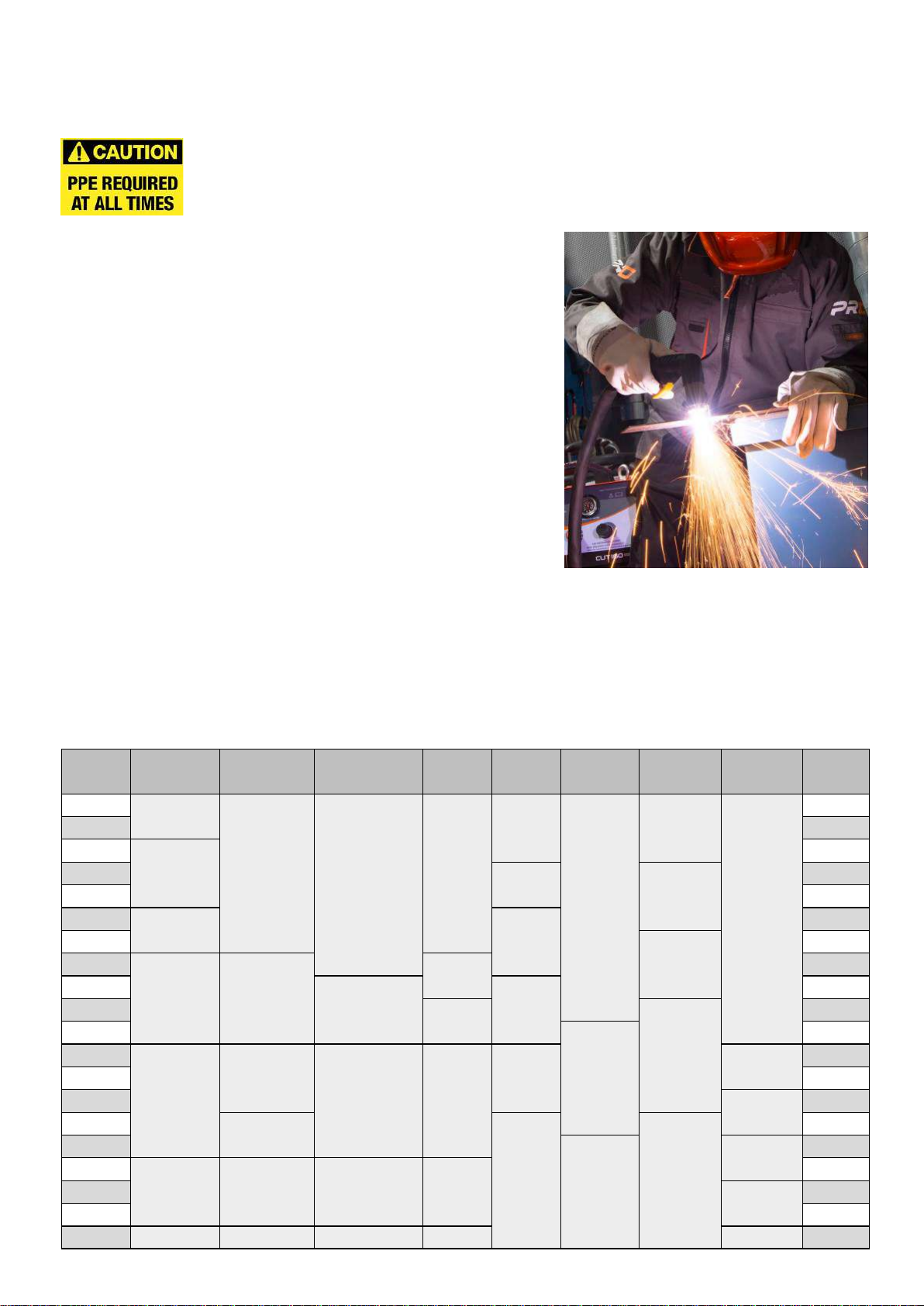
Use of Personal Protecve Equipment (PPE)
Welding arc rays from all welding and cung processes can produce intense, visible and
invisible (ultraviolet and infrared) rays that can burn eyes and skin.
• Wear an approved welding helmet ed with an appropriate
shade of lter lens to protect your face and eyes when
welding, cung or watching.
• Wear approved safety glasses with side shields under your
helmet.
• Never use any equipment that is damaged, broken or faulty.
• Always ensure there are adequate protecve screens or
barriers to protect others from ash, glare and sparks from
the welding and cung area.
• Ensure that there are adequate warnings that welding or
cung is taking place.
• Wear suitable protecve ame resistant clothing, gloves and
footwear.
• Ensure adequate extracon and venlaon is in place prior to
welding and cung to protect users and all workers nearby.
• Check and be sure the area is safe and clear of ammable material before carrying out any welding or
cung.
Some welding and cung operaons may produce noise. Wear safety ear protecon to protect your
hearing if the ambient noise level exceeds the local allowable limit (e.g: 85 dB).
Welding and Cung Lens Shade Selector Guide
Current MMA
Electrodes
MIG
Light Alloys
MIG
Heavy Metals MAG TIG Plasma
Cung
Plasma
Welding
Air Arc
Gouging Current
10 8
10 10 10
9
11
10
10
10
15 15
20
9
20
30 10 11
30
40 40
60 10 11
60
80
12
80
100
11 11
11 100
125
11 12
125
150 12
13
150
175
12
175
200
12
12
12 13
13 11 200
225 225
250 12 250
275 13
14 14
275
300
13
13 300
350
13 14 13 14
350
400 14 400
450 450
500 14 15 14 15 15 500
6
SAFETY INSTRUCTION
Safety against fumes and welding gases
The HSE have idened welders as being an ‘at risk’ group for occupaonal diseases arising
from exposure to dusts, gases, vapours and welding fumes. The main idened health eects
are pneumonia, asthma, chronic obstrucve pulmonary disease (COPD), lung and kidney
cancer, metal fume fever (MFF) and lung funcon changes.
During welding and hot cung ‘hot work’ operaons, fumes are produced which are
collecvely known as welding fume. Depending upon the type of welding process being performed, the
resultant fume generated is a complex and highly variable mixture of gases and parculates.
Regardless of the length of welding being carried out, all welding fume, including mild steel welding
requires suitable engineering controls to be in place which is
usually Local Exhaust Venlaon (LEV) extracon to reduce the
exposure to welding fume indoors and where LEV does not
adequately control exposure it should also be enhanced by using
suitable respiratory protecve equipment (RPE) to assist with
protecng against residual fume.
When welding outdoors appropriate RPE should be used.
Prior to undertaking any welding tasks an appropriate risk
assessment should be carried out to ensure expected control
measures are in place.
Locate the equipment in a well-venlated posion and keep your head out of the welding fume.
Do not breathe in the welding fume.
Ensure the welding zone is well-venlated and provision should be made for suitable local fume
extracon system to be in place.
If venlaon is poor, wear an approved airfed welding helmet or respirator.
Read and understand the Material Safety Data Sheets (MSDS’s) and the manufacturer’s instrucons for
metals, consumable, coangs, cleaners and de-greasers.
Do not weld in locaons near any de-greasing, cleaning or spraying operaons.
Be aware that heat and rays of the arc can react with vapours to form highly toxic and irritang gases.
For further informaon please refer to the HSE website www.hse.gov.uk for related documentaon.
Precauons against re and explosion
Avoid causing res due to sparks and hot waste or molten metal.
Ensure that appropriate re safety devices are available near the welding and cung area.
Remove all ammable and combusble materials from the welding, cung and surrounding
areas.
Do not weld or cut fuel and lubricant containers, even if empty. These must be carefully
cleaned before they can be welded or cut.
Always allow the welded or cut material to cool before touching it or
placing it in contact with combusble or ammable material.
Do not work in atmospheres with high concentraons of combusble
fumes, ammable gases and dust.
Always check the work area half an hour aer cung to make sure that
no res have begun.
Take care to avoid accidental contact of the torch electrode to metal
objects, as this could cause arcs, explosion, overheang or re.
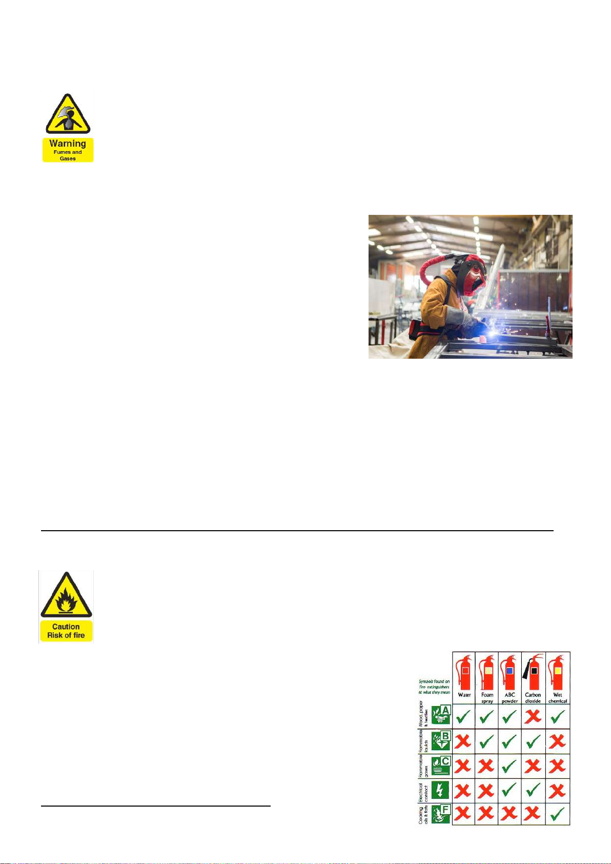
Know and understand your re exnguishers
An example of personal fume protecon
7
SAFETY INSTRUCTION
The working environment
Ensure the machine is mounted in a safe and stable posion allowing for cooling air circulaon.
Do not operate equipment in an environment outside the laid down operang parameters.
The welding power source is not suitable for use in rain or snow.
Always store the machine in a clean, dry space.
Ensure the equipment is kept clean from dust build up.
Always use the machine in an upright posion.
Protecon from moving parts
When the machine is in operaon keep away from moving parts such as motors and fans.
Moving parts, such as the fan, may cut ngers and hands and snag garments.
Protecons and coverings may be removed for maintenance and managed only by qualied
personnel aer rst disconnecng the power supply cable.
Replace the coverings and protecons and close all doors when the intervenon is nished and before
starng the equipment.
Take care to avoid geng ngers trapped when loading and feeding wire during set up and operaon.
When feeding wire be careful to avoid poinng it at other people or towards your body.
Always ensure machine covers and protecve devices are in operaon.
Risks due to magnec elds
The magnec elds created by high currents may aect the operaon of pacemakers or
electronically controlled medical equipment.
Wearers of vital electronic equipment should consult their physician before beginning any arc
welding, cung, gouging or spot welding operaons.
Do not go near welding equipment with any sensive electronic equipment as the magnec
elds may cause damage.
Keep the torch cable and work return cable as close to each other as possible throughout their length.
This can help minimise your exposure to harmful magnec elds.
Do not wrap the cables around the body.
Handling of compressed gas cylinders and regulators
Mishandling gas cylinders can lead to rupture and the release of high pressure gas.
Always check the gas cylinder is the correct type for the welding to be carried out.
Always store and use cylinders in an upright and secure posion.
All cylinders and pressure regulators used in welding operaons should be handled with care.
Never allow the electrode, electrode holder or any other electrically “hot” parts to touch a
cylinder.
Keep your head and face away from the cylinder valve outlet when opening the cylinder valve.
Always secure the cylinder safely and never move with regulator and hoses connected.
Use a suitable trolley for moving cylinders.
Regularly check all connecons and joints for leaks.
Full and empty cylinders should be stored separately.
Never deface or alter any cylinder
8
SAFETY INSTRUCTIONS
Fire awareness
The cung and welding process can cause serious risks of re or explosion.
Cung or welding sealed containers, tanks, drums or pipes can cause explosions.
Sparks from the welding or cung process can cause res and burns.
Check and risk assess the area is safe before doing any cung or welding.
Venlate all ammable or explosive vapour from the workplace.
Remove any and all ammable materials away from the working area. If necessary, cover ammable
materials or containers with approved covers (following manufacturers instrucons) if unable to remove
from the immediate area.
Do not cut or weld where the atmosphere may contain ammable dust, gas or liquid vapour.
Always have the appropriate re exnguisher nearby and know how to use it.
Hot parts
Always be aware that material being cut or welded will get very hot and hold that heat for a
considerably long me which will cause severe burns if the appropriate PPE is not worn.
Do not touch hot material or parts with bare hands.
Always allow for a cooling down period before working on material recently cut or welded.
Use the appropriate insulated welding gloves and clothing to handle hot parts to prevent burns.
Noise awareness
The cung and welding process can generate noise that can cause permanent damage to your
hearing. Noise from cung and welding equipment can damage hearing.
Always protect your ears from noise and wear approved and appropriate ear protecon if
noise levels are high.
Consult with your local specialist if you are unsure how to test for noise levels.
RF Declaraon
Equipment that complies with direcve 2014/30/EU concerning electromagnec compability
(EMC) and the technical requirements of EN60974-10 is designed for use in industrial buildings
and not for domesc use where electricity is provided via the low voltage public distribuon
system.
Dicules may arise in assuring class A electromagnec compability for systems installed in domesc
locaons due to conducted and radiated emissions.
In the case of electromagnec problems, it is the responsibility of the user to resolve the situaon.
It may be necessary to shield the equipment and t suitable lters on the mains supply.
LF Declaraon
Consult the data plate on the equipment for the power supply requirements.
Due to the elevated absorbance of the primary current from the power supply network, high
power systems aect the quality of power provided by the network. Consequently, connecon
restricons or maximum impedance requirements permied by the network at the public network
connecon point must be applied to these systems.
In this case, the installer or the user is responsible for ensuring the equipment can be connected,
consulng the electricity provider if necessary.

9
SAFETY INSTRUCTION
Materials and their disposal
Welding equipment is manufactured with BSI published standards meeng CE requirements for
materials which do not contain any toxic or poisonous materials dangerous to the operator.
Do not dispose of the equipment with normal waste.
The European Direcve 2012/19/EU on Waste Electrical and Electronic Equipment states that electrical
equipment that has reached its end of life must be collected separately and returned to an
environmentally compable recycling facility for disposal.
For more detailed informaon please refer to the HSE website www.hse.gov.uk
PACKAGE CONTENTS AND UNPACKING
Supplied within your new Weld Star Innium product package will be the following items with each
model.
Use care when unpacking the contents and ensure all items are present and not damaged.
If damage is noted or items are missing, please contact the supplier in the rst instance and before
installing or using the product.
Record the product model, serial numbers and purchase date in the informaon secon found on the
inside front page of this operang manual.
Weld Star WS-MU4-1 ACDC LCD
Weld Star MU4-1 Power Source
Titanium T240 3M MIG Torch (T240-3)
Titanium 26 Tig Torch 12 (TIG-103)
MMA work lead
Work Return Lead
Gas Regulator
Gas Hose
0.8mm/1.0mm V feed roll
USB Sck including Operang Manual
Please Note:
• You may note that the package contains 2 spare brackets, if so, these are only required if you have
or do purchase the Weld Star 2 wheel trolley WS-T2.
These brackets allow the MU4-1 machine to be secured to the trolley shelf.
• Package contents may very depending on country locaon and package part number purchased.

10
PRODUCT OVERVIEW
The Weld Star MU4-1 is a true mul-process inverter welder oering professional welding performance
in all processes and is the rst of its kind to include pulse technology in MIG, TIG and MMA, making it
the most versale machine on the market today.
It has been designed to incorporate the most advanced features and technology
oering the operator a user-friendly interface via the 5” true colour LCD display.
Welding process’s include:
MIG/MAG Synergic
MIG/MAG Pulse
MIG/MAG Standard
TIG AC (HF/LIFT)
TIG DC (HF/LIFT)
MMA AC
MMA DC
Weld Star Plasma WS-MU4-1 Product Features:
• Advanced IGBT mul-process inverter technology which
is compact and lightweight at only 20kg
• PFC technology oering mulple advantages such as energy
eciency and wide range input voltage from 95Vac – 265Vac
• Wired and wireless remote control opons
• Generator friendly
• Smart fan – reduces power consumpon and intake of dust and fumes
• IP23 protecon
• Built to EN-60974-1 and is fully compliant with the European Commission Regulaon 2019/1784,
CE and UKCA
• With synergic MIG/MAG, welding parameters can be automacally selected based on material
thickness and voltage with synergic curves for common materials and wires
• Integrated TIG welding features such as HF or li TIG, pre/post ow gas mes, 2T/4T, slope up/down
and pulse, all to ensure excellent TIG welding characteriscs in both AC and DC
• SMART TIG funcon with advanced TIG welding features, such as mul-wave, Q start and hybrid TIG,
whilst sll maintaining ease of set up for the user
• DC and AC MMA suitable for a wide range of electrodes
• Advanced MMA features such as pulse and automac current regulaon based on electrode
diameter
• Hot start arc ignion funcon which ensures excellent arc ignion in MMA for easier and more
reliable arc starng
• Self adapve arc force technology which maintains MMA arc condions during operaon even with
long welding cables
• In-built VRD (MMA and TIG mode only)
• Designed for gas and gasless MIG welding wires.
• Ability to save up to 10 stored programs for quick set up
• Advanced error code menu for ease of fault and troubleshoong diagnosis
• Panel mounted USB connecon for quick and easy rmware updates
• Available with a wide range of accessories including on torch remote, foot pedal, spool on gun
and 2 wheel trolley

11
TECHNICAL SPECIFICATIONS
Parameter Unit Weld Star WS-MU4-1
Rated input voltage V
Wide Voltage 95Vac – 265Vac
AC110V (±15%) 50/60Hz AC230V (±15%) 50/60Hz
Rated input power kVA 4.5 7.5
Rated input current Imax
A
MIG 35
TIG AC 31.5 / DC 33
MMA AC 36.5 / DC 39.5
MIG 28
TIG AC 21 / DC 22.5
MMA AC 30.5 / DC 33.5
Rated input current Ie
A
MIG 17.5
TIG AC 16 / DC 16
MMA AC 18.2 / DC 19.7
MIG 14
TIG AC 10 / DC 11
MMA AC 15 / DC 17
Welding current range
A
MIG 10 ~ 140
MMA 5 ~ 130
TIG 5 ~ 160
MIG 40 ~ 200
MMA 5 ~ 200
TIG 5 ~ 200
No-load voltage
V
MIG 28
MMA 75
TIG 75
Rated duty cycle (40°C)
%
MIG 140A @ 25%
MMA AC/DC 130A @ 25%
TIG AC/DC 160A @ 25%
MIG 200A @ 25%
MMA AC/DC 200A @ 25%
TIG AC/DC 200A @ 25%
Eciency %85
Idle state power W30
Power factor cosφ0.99
Standard - EN60974-1
Protecon class IP IP23
Insulaon class - H
Noise db <70
Humidity %<90% (20°C)
Operang temperature range °C -10 ~ +40
Storage temperature °C -25 ~ +55
MIG Torch - Titanium T240 3m
MIG recommended wire size mm FE: 0.6/0.8/1.0 - SS: 0.8/1.0 - Flux Cored: 0.6/0.8/1.0
Wire reel weight/spool size kg/mm 5kg / 200mm
MMA recommended
electrode size mm 1.6 ~ 3.2 1.6 ~ 4.0
Overall size mm 620 X 220 X 370 (without handle)
620 X 220 X 430 (with handle)
Weight kg 20
12
CONTROLS
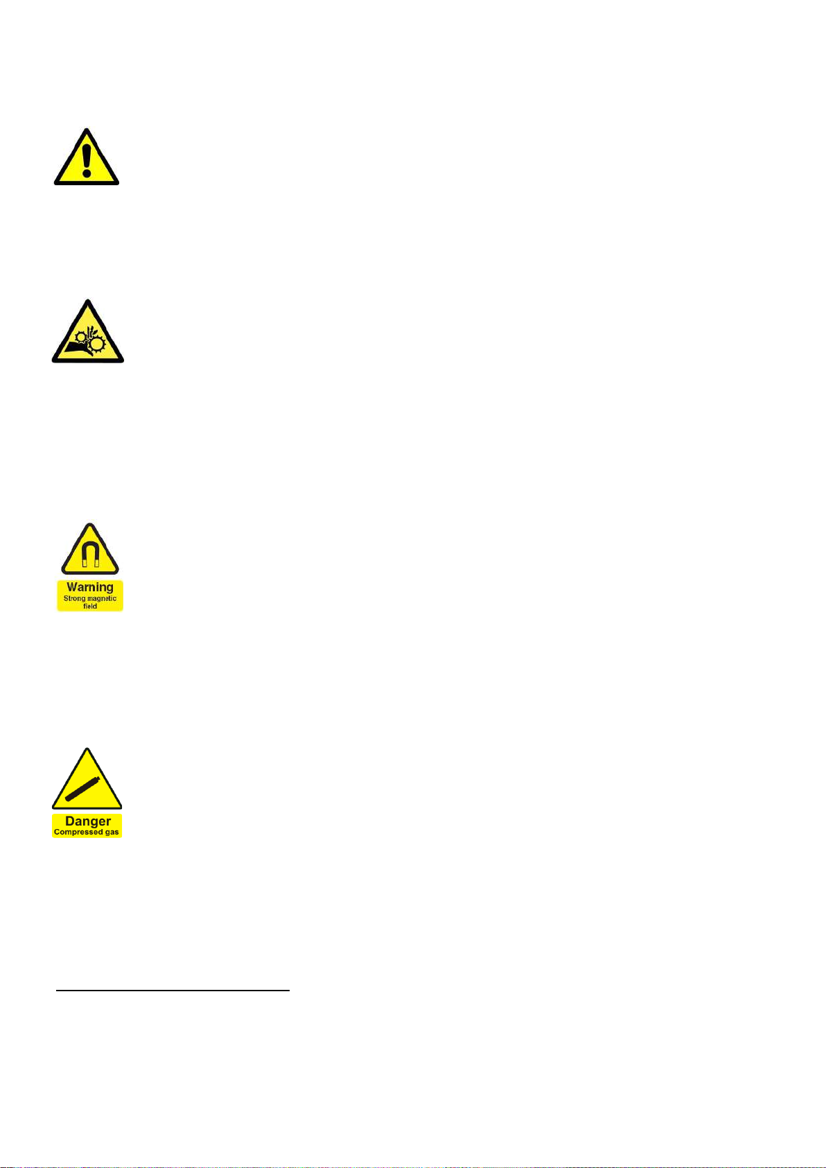
Front view Weld Star WS-MU4-1
1. Protecve control panel cover
2. Control panel (see below and page 16 for further informaon)
3. Posive ‘+’ Dinse socket outlet (35/50mm)
4. MIG Torch outlet connector, the connecon that allows for a euro
style MIG torch to be ed
5. 9 Pin remote control socket (12 pin on early models) see page 61
for further informaon
6. Cooling air vent
7. TIG gas outlet (10mm)
8. Negave ‘-’ Dinse socket outlet (35/50mm)
Rear view Weld Star WS-MU4-1
9. Protecve control panel cover
10. Carry handle
11. Gas inlet
12. Air vent
13. Mains power ON/OFF switch
14. Mains input power cable
Control panel view Weld Star WS-MU4-1
27 USB Connector *
28 5” Digital screen
29 Le control buon
30 Main control dial and acvaon buon
31 Right control buon
* The front panel USB socket allows for easy
soware updates to be loaded into the machine.
By inserng a ‘loaded’ Weld Star USB while the
machine is turned o and then switching the
machine ON will the machine automacally load
the updated rmware and programs (during this mode the screen displays the rmware update status).
Once the update is complete the machine will boot up as normal.

13
CONTROLS
Side view Weld Star WS-MU4-1
15. Carry handle
16. Rear panel (see page 12 for further informaon).
17. Wire spool holder and tensioner: Allows a 5kg (200mm diameter) reel of wire to be located in place
via an alignment pin and then locked in place with the locking nut. The spool holder also has a brake
arrangement to ensure correct tension of the wire, this is done by turning the central bolt with an
allen key clockwise (to ghten) or an clockwise (to loosen).
18. Rear air vent.
19. Protecve control panel cover.
20. Adjustment point to euro MIG torch outlet polarity to be either posive ‘+’ or negave ’–’.
When using gas set the connecon to ‘+’ when using ‘gasless’ welding wire set the connecon to ‘–’.
21. Control panel (see page 12 and from page 16 for further informaon).
22. Drive Assembly feed motor and gearbox (the feed motor is located behind the plasc cover).
23. Upper pressure roll assembly: Holds the upper drive roll in place which applies pressure to the
welding wire via the ed grooved drive roll, the pressure is applied via the drive roll tensioner which
allows the correct amount of tension to be applied to the top roller to ensure good feed of the wire
through the MIG torch.
24. Outlet feed adaptor: Part of the Euro outlet connector assembly which contains the inner outlet guide
which ensures smooth wire feed from the drive assembly through to the MIG torch.
25. Wire feed roller and retaining nut. Secures and holds the grooved drive roll in place. The feed roll
supplied with the machine is a 0.8mm/1.0mm V
26. Inlet wire guide: The welding wire is fed through the inlet guide prior to feeding through the drive
rollers.

14
INSTALLATION
Unpacking
Check the packaging for any signs of damage.
Carefully remove the machine and retain the packaging unl the installaon is complete.
Locaon
The machine should be located in a suitable posion and environment. Care should be taken to avoid
moisture, dust, steam, oil or corrosive gases.
Place on a secure level surface and ensure that there is adequate clearance around the machine to
ensure natural airow.
Input connecon
Before connecng the machine you should ensure that the correct supply is available. Details of the
machine requirements can be found on the data plate of the machine or in the technical parameters
shown in the manual.
The equipment should be connected by a suitably qualied competent person. Always ensure the
equipment has a proper grounding.
Never connect the machine to the mains supply with the panels removed.
Output connecons
Electrode polarity
In general when using manual arc welding electrodes the electrode holder is connected to the posive
terminal and the work return to the negave terminal. Always consult the electrode manufacturer’s
data sheet if you have any doubts.
MMA welding
Insert the cable plug with electrode holder into the “+” socket on the front panel of the welding
machine and ghten it clockwise.
Insert the cable plug of the work return lead into the “-” socket on the front panel of the welding
machine and ghten it clockwise.

15
INSTALLATION
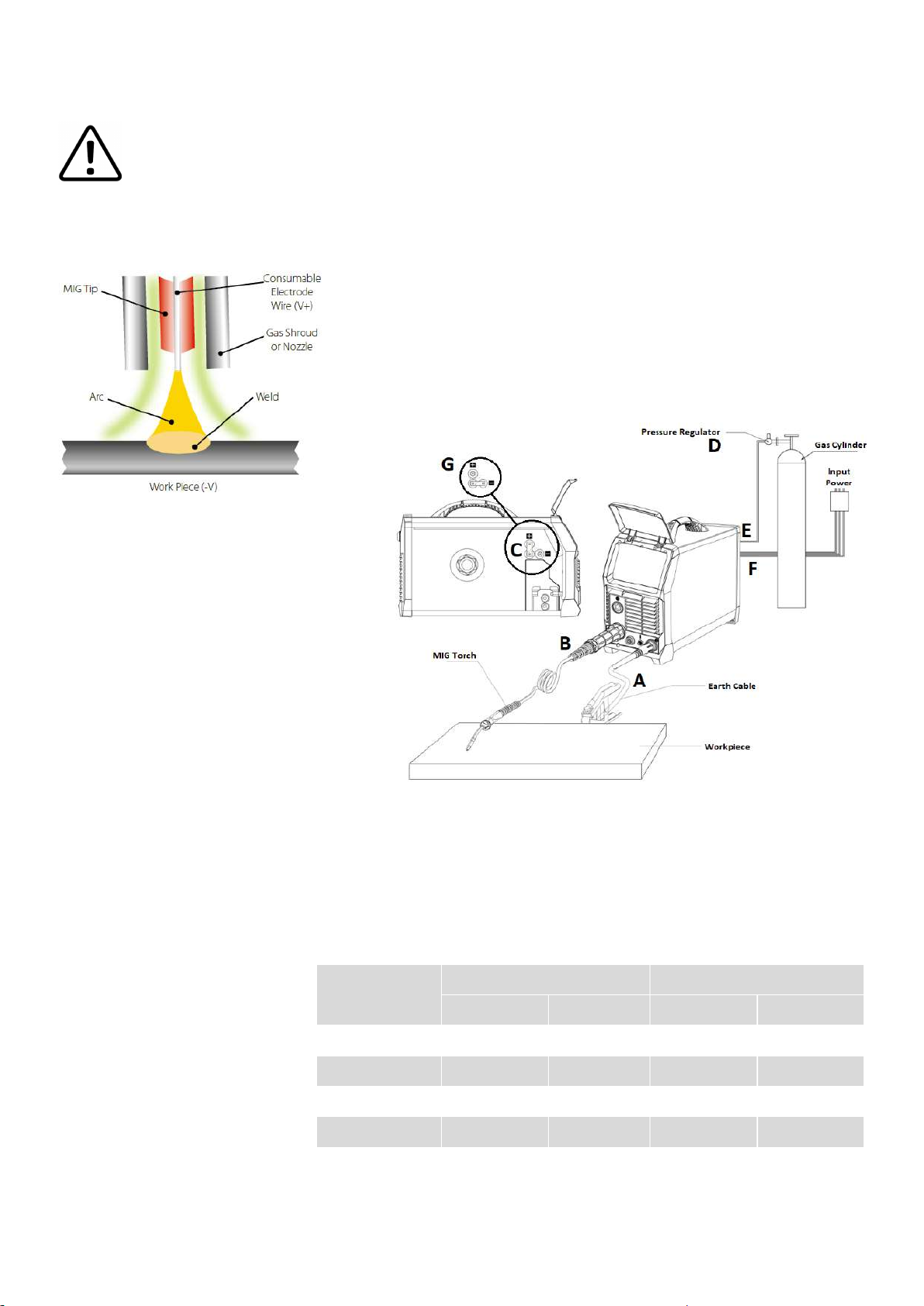
MIG welding
• Insert the welding torch (B) into the “Euro connector for torch in MIG” output socket on the front
panel of the machine and ghten it into posion.
• Insert the work return lead cable plug (A) into the “-” output terminal of the welding machine and
ghten by rotang it clockwise.
• Ensure that the link (C) the torch polarity connecon link is in the vercal posion and connected to
the “+” terminal, this ensure that’s the MIG torch polarity is posive (+).
• Install the welding wire on the spindle adapter (I).
• Connect the cylinder (H) equipped with the gas regulator (D) to the gas inlet on the back panel of the
machine (E) with a gas hose.
• Ensure that the wire groove size of the ed drive roll matches the contact p (ed to the MIG
torch) and the welding wire size being used.
• Release the pressure arm of the wire feeder to thread the wire through the guide tube and into the
drive roll groove and then adjust the pressure arm, ensuring no sliding of the wire. (too much pressure
will lead to wire distoron which will aect wire feeding).
• Turn the machine ON
• Via the user display, place the welding mode funcon into the MIG posion (see page 16).
• ‘Inch’ the welding wire through the MIG torch and out via the contact p (see page 16).
• You are now ready to start MIG welding.
Gasless self shielded MIG welding
When carrying out MIG welding with gasless welding wire the welding torch polarity is reversed, so the
MIG torch is ‘-’ and the work return lead is ‘+’
Follow the above procedure except for the following:
• Insert the work return lead cable plug (A) into the “+” output terminal of the welding machine and
ghten by rotang it clockwise.
• Ensure that the link (G) the torch polarity connecon link is in the horizontal posion and connected
to the “-” terminal, this ensure that’s the MIG torch polarity is now negave (-).
• Ensure that you have turned OFF the gas supply at the cylinder.
A
B

16
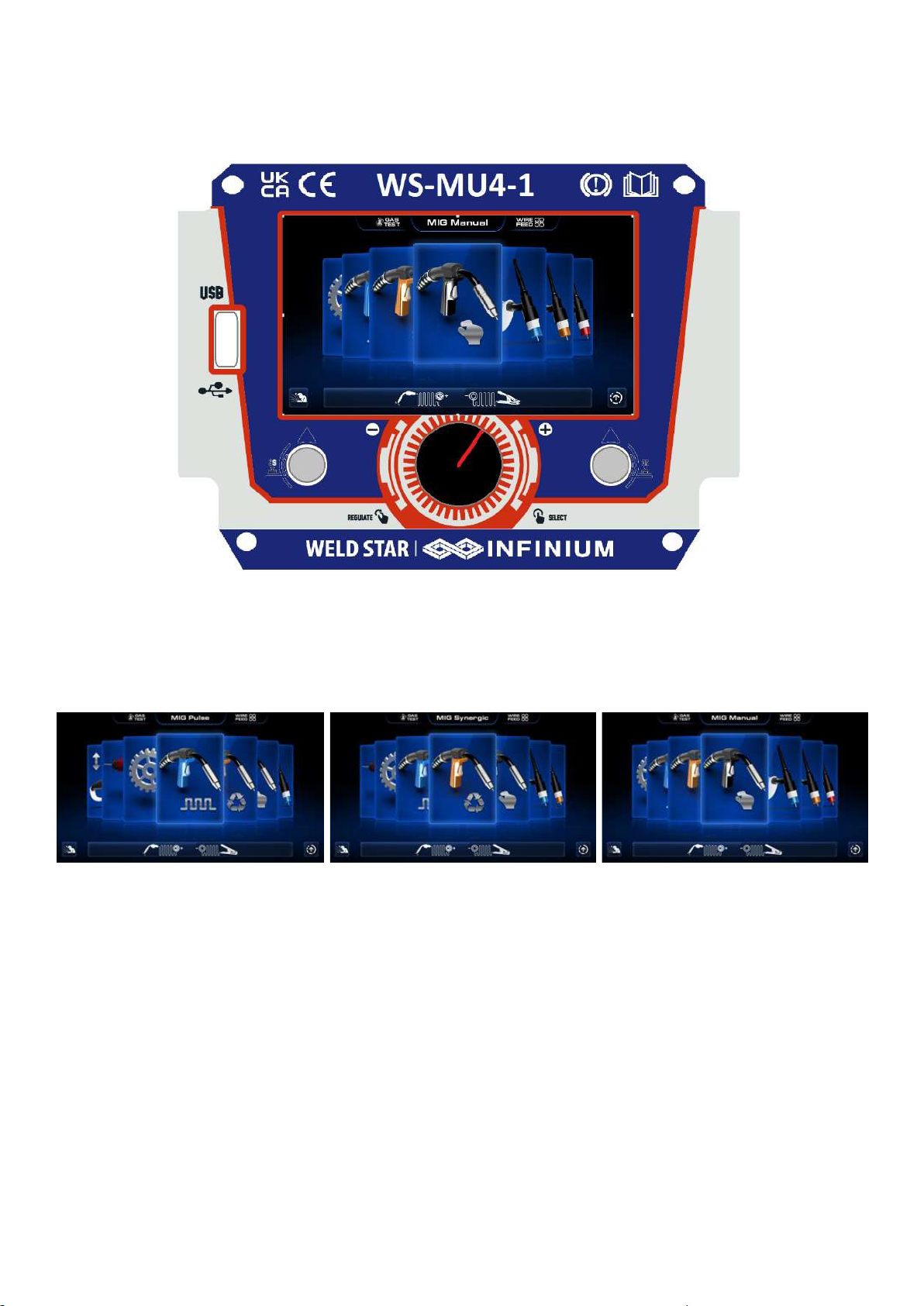
MULTIFUNCTIONAL DISPLAY WINDOW
Display Screen Explained WS-MU4-1
Upon powering ON your MU4-1 and boot up sequence is complete, the main menu will appear on the
LCD digital screen ’F’ as shown right, this allows the operator to navigate the various welding processes
by rotang the control dial ‘B’ clockwise or an
clockwise and when the desired opon is front
and centre then you can press the dial ‘B’ to
access the required welding mode.
Along with the sengs opon you can also
navigate yourself though the welding modes
that include: MMA, MIG Pulse, MIG Synergic,
MIG Standard, Li TIG, HF TIG and Smart TIG.
Buon ‘A’ is usually associated with the icon
that’s circled ‘D’ (to access opon short press A).
Buon ‘C’ is usually associated with the icon
that’s circled ‘E’ (to access opon short press C).
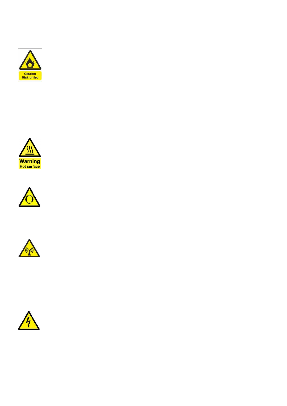
Navigate to one of the MIG welding process opons, the example
shown le is MIG manual, you will then note that just above the
control dial circled ‘H’ it shows the polarity of the MIG torch and
work return lead:
• MIG torch symbol is ‘+’ (posive polarity)
• Work return lead clamp is ‘-’ (negave polarity)
To check that the outputs are congured correctly, please check
out pages 15-16 to adjust and set if required.
In this screen you also have the ability to check and acvate gas
purge along with ‘inching’ the wire feed.
• If you long press and release buon ‘A’ (approx. 3 seconds) the gas solenoid will acvate allowing the
gas to purge and ow, allowing you to test and set the gas ow accordingly.
• If you long press and release buon ‘C’ (approx. 3 seconds) this acvates the wire feed motor which
in turn pushes the welding wire through the MIG torch and contact p.
If you press the control dial ‘B’ buon, this will take you to the MIG manual welding process control
screen, as shown le, where you can adjust (in this case being
MIG Manual) the following sengs:
• 1Wire Feed Speed
• 2Welding Voltage
• 3MIG Torch switch control, 2T, 4T, S4, Spot and S2t
• 4Variable MIG Inductance control
To access these advanced seng, press the control dial ‘B’ and
each of the green circled parameters numbered 1 - 4 will highlight
red in turn as you rotate the control dial B.
To adjust a highlighted parameter, press the control dial which
will allow you to adjust selected parameter by rotang the dial and then pressing the control dial again
will store the parameter seng and automacally move to the next parameter opon.
Please Note: Parameter opons vary depending on welding process and torch trigger mode selected.
17
MULTIFUNCTIONAL DISPLAY WINDOW
Display Screen Explained WS-MU4-1 (connued)
As previously noted buons A and C have 2 funcons determined
by either a short or long press of buons A and C.
• Briey pressing buons A or C will acvate the 2 opon icons
circled purple.
• Pressing, holding the releasing buons A and C for approx. 3
seconds will acvate the 2 opon circled in green (save and
load in this case).
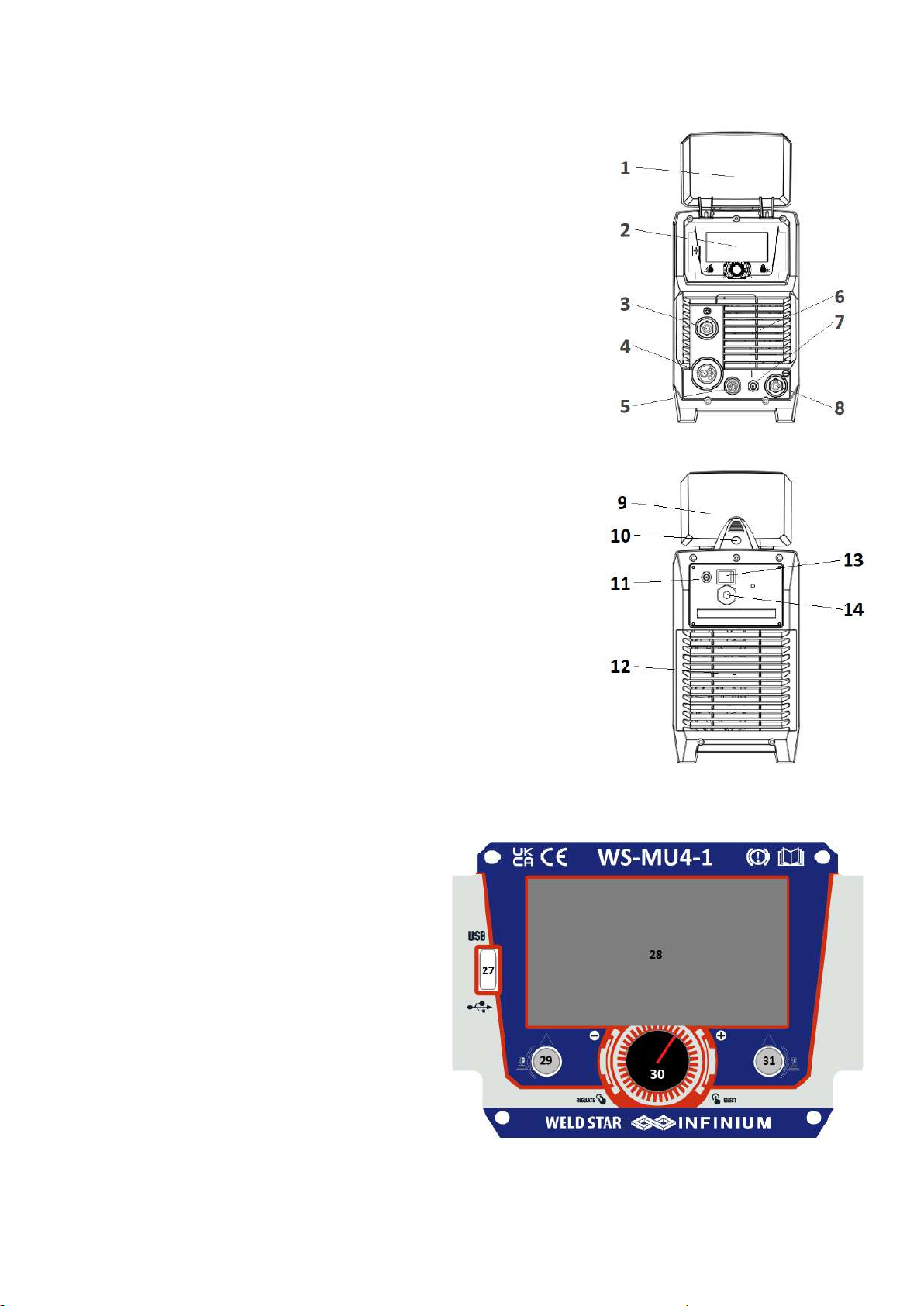
Following on from the instrucons on the previous page, if you
press and release (short press) buon ‘C’ you will now enter a
new screen (shown le) that allows the operator to select and
adjust more advanced (in this case) MIG sengs such as:
• Pre gas ow
• Slope up
• Current
• Slope down
• Post gas ow
• Burn back
• Also Start Amps, Start Amps me and nal amps are available
in either S2t or S4t torch trigger mode.
Please Note: These parameter opons do change depending on which welding process and torch trigger
mode you have selected.
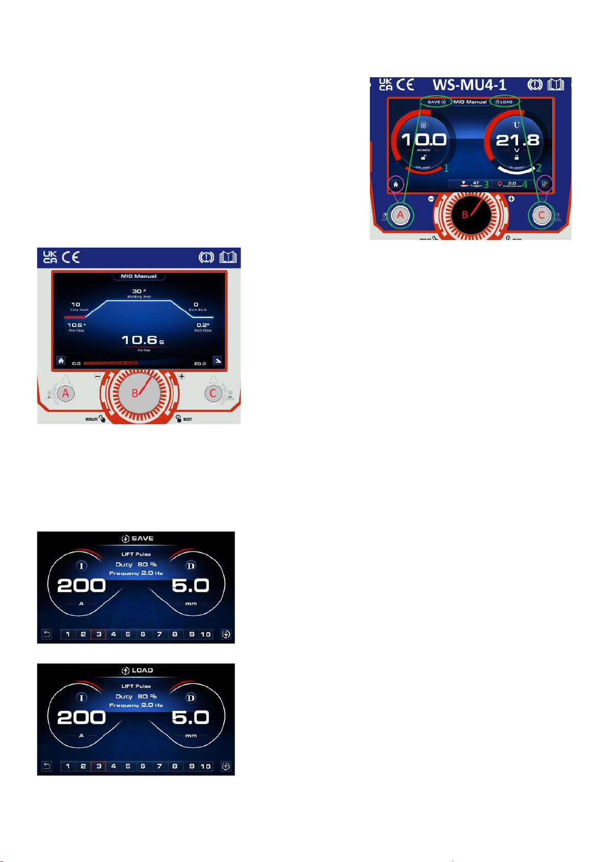
Save and Loading welding programs
The following informaon details the save and load opons of welding parameters as detailed below:
Saving a welding program
If you long press (approx. 3 seconds) and release buon ‘A’ the
screen will change to the memory save opon.
As you will see this screen allows the operator to save his setup
to 1 of 10 memory programs.
To save, rotate the control dial to the desired program number
and then press and release buon ‘C’.
Loading a welding program
If you long press and release buon ‘C’ (for approx. 3 seconds)
the screen will change to the memory load opon.
This screen allows the operator to load previously saved welding
programs.
To load a program, rotate the control dial to the desired program
number and then press and release buon ‘C’
You will then return to the loaded welding program screen.
18
OPERATION - MIG/MAG
Before starng any welding acvity ensure that you have suitable eye protecon and
protecve clothing. Also take the necessary steps to protect any persons within the welding
area.
MIG/MAG welding mode
MIG - Metal Inert Gas Welding, MAG - Metal Acve Gas Welding, GMAW - Gas Metal Arc Welding
MIG welding was developed to help meet producon demands of the
war and post war economy which is an arc welding process in which a
connuous solid wire electrode is fed through a MIG welding gun and
into the weld pool, joining the two base materials together.
A shielding gas is also sent through the MIG welding gun and protects
the weld pool from contaminaon which also enhances the arc.
Connect the MIG torch as shown (B)
Work return lead to ‘-’ (A)
Ensure that a suitable inert gas supply is
connected (E).
Switch the power switch on the back panel
to “ON” (F) the machine is started with the
panel display coming ON.
Via the display navigate to welding mode
and set welding mode to MIG or MIG
synergic depending on your applicaon.
Open the gas valve of the cylinder and adjust
the gas regulator to obtain the desired ow rate (D).
Adjust the displays MIG sengs on the machine control panel to get the correct desired welding
condion of welding voltage, current etc (see page 17 for further info on the control panel display
funcon)
Operate the torch trigger and welding can be carried out, (Note: Once the MIG torch switch is pressed, if
no welding current is sensed within 5 seconds, wire feed, gas and output voltage will stop).
The below MIG wire guide can vary depending on material used, work piece thickness, welding posion
and joint form.
MIG - Gasless Welding
The operaon method is the
same as the above MIG
operaon except there are no
gas opons and the output
polarity is reversed (G in above
image).
Please Note:
Before starng any welding acvity ensure that you have suitable PPE including eye protecon and
protecve clothing. Also consider and take the necessary steps to protect any persons within the area.
Wire Diameter DIP Transfer Spray Transfer
(mm) Current (A) Voltage (V) Current (A) Voltage (V)
0.6 30 ~ 80 15 ~ 18 n/a n/a
0.8 45 ~ 180 16 ~ 21 150 ~ 250 25 ~ 33
1.0 70 ~ 180 17 ~ 22 230 ~ 300 26 ~ 35
1.2 60 ~ 200 17 ~ 22 250 ~ 400 27 ~ 35
1.6 100 ~ 280 18 ~ 22 250 ~ 500 30 ~ 40
19
MULTIFUNCTIONAL DISPLAY WINDOW - MIG MODE
Welding screen/display explained MU4-1
Upon powering ON your WS-MU4-1 and boot up is complete, the control panels main menu will appear
on the digital panel as shown above.
You can now navigate yourself though the various opons and welding modes which include:
Sengs, MIG Pulse, MIG Synergic, MIG Manual, Li TIG, HF TIG, Smart TIG and MMA.
In the home screen, for MIG welding the following opons are available:
MIG Pulse MIG Synergic MIG Manual
By rotang the main centre control dial you will ’scroll’ through the opons and by pressing the dial you
will enter either MIG Pulse, MIG Synergic or MIG manual mode.
Convenonal MIG welding equipment (MIG manual) run at a steady single amperage where the operator
has access and controls of the wire feed speed rate and the welding voltage whereas with MIG pulsed
welding the machine runs a peak and a background amperage and the unit will constantly switch between
the two amperages enabling the operator to put out a lower overall heat input into the material.
One of the benets of MIG pulse includes smoother spaer free welding to help prevent blowing through
thin material.
When MIG synergic welding is referred to it means that when a single seng is adjusted (voltage or
material thickness) the other sengs like current or wire speed change automacally.
Please Note:
When in the selecon screens (as above) for MIG welding modes, pressing and holding either the
boom le or the boom right buons will give you the facility of ‘Gas Test’ or ‘Wire Feed Inch’ which
are noted in the top line of the display.

20
MULTIFUNCTIONAL DISPLAY WINDOW - MIG MODE
Welding screen/display explained MU4-1
When selecng either MIG pulse or MIG Synergic mode, the operator has the opon to select material,
gas and wire size as shown below, this selecon is carried out by rotang and pressing the main dial to
select the desired opon.
Material selecon choice is as follows:
• FE - Mild Steel
• Flu.Fe - Flux Cored
• Ss - Stainless Steel
• AlMg - Aluminium Magnesium
Gas selecon choice is as follows:
• 80% Ar 20%C02
• 100% C02
Wire diameter size selecon choice is as follows:
• 0.6mm (0.024)
• 0.8mm (0.032)
• 0.9mm (0.035)
• 1.0mm (0.039)
At this point the bar along to boom of the screen does show the operator welding mode, material, gas
and wire size that have selected.
Once you have selected the key welding setup parameters as shown above, you will now enter the main
welding screen that displays centrally your chosen MIG process, material, gas and wire size.
As the above screens show, the le circular secon oers either current or wire feed seng and the right
secon shows voltage/arc length and these opons can vary depending on which MIG process has been
selected.
The boom row shows, material thickness, torch trigger mode and inductance control and to adjust each
seng, simply press the control dial unl the parameter you wish to adjust is highlighted in red and then
rotate the dial to adjust said parameter, pressing the control dial again stores that parameter seng.
When in Pulse MIG you have an addional feature called ‘Wire retract’ which is only eecve when
welding aluminum material. When ‘Wire Retract’ is set it ON (see page 60), at arc starng the welding
wire will briey retract when rst touching the workpiece and the inial start current is lowered to
enhance weld starng properes. When set to OFF the ’Wire Retract’ feature will not be acve.
Table of contents
Other Infinium Welding System manuals


Popular Welding System manuals by other brands


Lincoln Electric
Lincoln Electric PRO-MIG 175 IM810 Operator's manual

voestalpine
voestalpine Bohler URANOS 4000-5000 GSM instruction manual

Cloos
Cloos Micro Pulse 300 Operating instructions and spare parts list

Cebora
Cebora MONO STAR MIG 1620/M instruction manual

Snap-On
Snap-On MIG185i manual

Masterweld
Masterweld MW2050 Instructions for use and maintenance

Rothenberger
Rothenberger ROWELD P 315 W Instructions for use

CREPoW
CREPoW MULTIMIG 400F SYN Operator's manual

Parkside
Parkside PFDS 33 B4 Operation and safety notes

Everlast
Everlast Powertig 255 EXT Operator's manual

Miller
Miller AlumaPower 350 MPa owner's manual

Geberit
Geberit UNIVERSAL operating instructions