Denkmeier BINOTRON-27 User manual

BINOTRON-27 Quick Reference Instructions
Please carefully read and follow these instructions. It is a very ood idea to become familiar with how the innovative
BINOTRON-27 eyepiece holders work. This will prevent confusion when operatin in the field.
Figure 1. Figure 2. Figure 3.
Usin the Eyepiece Holders Properly
1. In figure 1. The Diopter Ring has been turned Counter-Clockwise (CCW) so that the third gradient line is
showing. If both eyepiece holders are set in this manner always, each eyepiece may be moved up or down to
fine-ad ust focus for each of your eyes at the telescope.
2. Now grasp the diopter ring to prevent it from rotating, and turn the Eyepiece Locking Ring above it CCW.
This will release the hold on the Dust Plug and the Dust Plug can now be removed as shown in figure 2.
3. Now load your eyepiece into the holder. If the eyepiece barrel is not entering the eyepiece holder easily, turn
the Eyepiece Lock Ring a bit more CCW until the eyepiece barrel enters smoothly (only 1.25" format eyepieces
can be used in The BINOTRON-27)
4. Now while holding the Diopter Ring securely once again, turn the Eyepiece Lock Ring Clockwise to tighten
the Eyepiece Lock Ring. It does NOT need to be over tightened. Just moderate finger pressure is adequate. You
are now ready to observe in your telescope. The eyepiece is being held in a self-centered method 360 degrees.
Follow the BINOTRON-27 Manual for your particular telescope type (Ex: SCT, Refractor, Newtonian). The
main telescope focuser is always used first to achieve focus and then the Diopter Rings on the binoviewer
eyepiece holders can be used for super fine-tuning the focus for each individual eyepiece if necessary.
Collimatin The BINOTRON-27
Each BINOTRON-27 has been accurately collimated to a high degree before shipping. However, we encourage
you to learn how to collimate. It's quite easy and you cannot damage the binoviewer if our instructions are
followed. After a little practice, you will find that the BINOTRON-27 Eyepiece Holders can be finely aligned at
the telescope in one minute or less! When we mention "collimating the Binoviewer", we are referring to aligning
the eyepiece holders. The prisms are carefully installed by us and set to an ideal position in our lab so that the
final alignment is accomplished with the eyepiece holders. This results in a perfectly collimated binoviewer.
Quick Instructions: Refer to the Main Manual for Additional Details
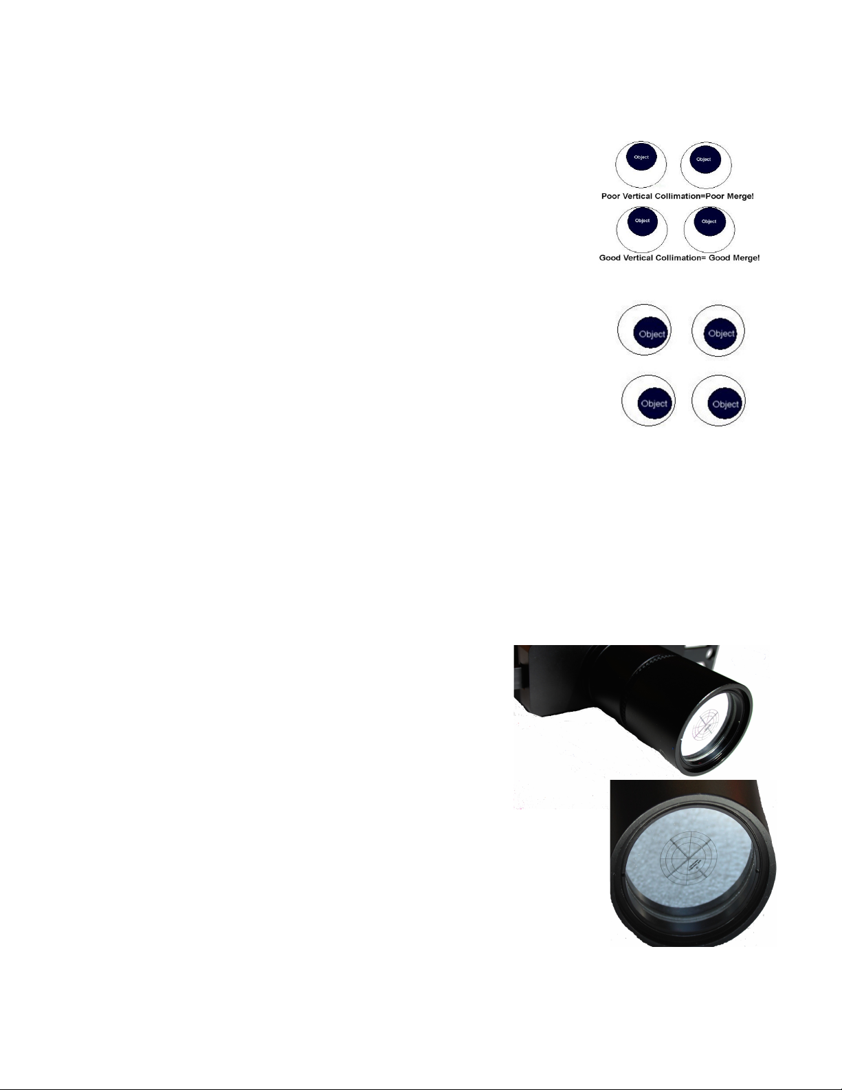
If you feel that the Binoviewer is producing uncomfortable or double images, please refer to Figs. 5 and 6 first.
It is best to view a stationary target in daytime to ob ectively determine if the eyepiece holders need re-
alignment. Observing a planet in your telescope is also a good measure, and the eyepiece holders can be ad usted
in in that application until the two-eyed image becomes a single perfectly merged
image that is very comfortable to view.
1. Fold the binoviewer body first so that the eyepieces match the width of your eyes.
You will see the image comfortably without a dark space in the center of the field.
This interpupillary (IP) ad ustment must be done with all binoculars and binoviewers.
It is best to fold the bino inward past the best point and then outward again to be sure
you have arrived at the best IP Width.
2. If you wish to ad ust The BINOTRON-27 collimation, loosen the lowest Fig 4
large silver Collitron Ring (fig 4) by rotating it counter-clockwise until the entire upper series of black sections
(Grasp The Diopter Rin to Shift) can be shifted in a flat circular motion. Both the right and left Collitron
Rings should be loosened in this way. Do not over-loosen the large silver Collitron Ring. the idea is that the
upper black section of the eyepiece holder which includes the Diopter and the Eyepiece Lock Rings can be
shifted in a flat plane but should not tilt or rock excessively. Shift by grasping the wide black Diopter Ring.
3. View a daytime or nightime ob ect (nightime: planet is best) and shift both holders at the same time while
viewing. The target being viewed will separate and then come together. It is best to produce a good merged
image by moving both holders to the central area of their ran e and work them both together in this middle
range. When a nice merge image is produced, tighten down ONE holder's Collitron
Ring using a fair amount of finger pressure.
4. Now, you can snug down the other holder's Collitron Ring, but not so tight that the
holder cannot be shifted a small amount when using a fair amount of finger pressure.
5. Place the ob ect being viewed at the top area of the eyepiece field at 12 o'clock
position but not quite touching the edge of the field. This is why a stationary daytime
ob ect is easier to work with. See Figure 5. Is the ob ect located in the same position
relative to the eyepiece field's edge in both the right and left eyepieces?
If not, ad ust the eyepiece holder by pushing it in one direction or Fig 5
another. The eyepiece field can be imagined as a circle surrounding an ob ect. That
circle will move in the direction that you push the holder. So, in the example shown in
figure 5 at the top, the right holder must be pushed in a downward motion. After this
has been done, the result is seen in the bottom of figure 5
6. Horizontal position of the ob ect should also be checked alternately as the holders
are ad usted with one another. Note that some offset in the ob ects position in the
Horizontal aspect is acceptable, and can even create an increased sense of 3-D. In
everyday life, we see ob ects in 3-D because we are viewing them from different angles
with our right and left eyes and in reality, the position of close by ob ects are offset in
the horizontal position in each eye . However, the vertical locations shown in the Fig 6
lower half of Figure 5 must be adhered to or a poorly merged and uncomfortable view will result.
Figure 6 shows some offset in the horizontal (upper), and then matched positions (lower).
The right holder has been shifted left to bring the ob ect closer to the field edge in the lower view. As mentioned,
some small differences in the horizontal positions of an ob ect in the right and left eyepieces is acceptable.
However, we do collimate the holders before shipping so that both Vertical and Horizontal are very closely
matched.
Collitron Ti htenin Tool
These tools as shown in the main manual are being machined and if not already included, will be shipped to you
as soon as they are ready. Note that any tool, even a thin philips screwdriver can be inserted to the holes and you
can rotate the Collitron Ring clockwise to increase the tightness. There is no need to over-ti hten this rin .
Collimatin Indoors Without a Telescope
We are now producing, and expect to have ready a special 2" reticle
device called The Collitron Reticle. It allows you to collimate the
BINOTRON-27 eyepiece holders indoors. All that you need are a pair
of eyepieces loaded in the binoviewer. Instructions will be included.
The image at the right shows what The Collitron Reticle looks like. The
Collitron Reticle assembly threads right into the Power Switch of the
Binoviewer. after other parts are threaded out. The reticle image can
then be viewed through the eyepieces of the binoviewer. It is very easy
to use and I can consistently collimate the holders in a minute or less to
a very high level of accuracy! Email us for pricing and availability.
Avoidin Problems
The main source of problems using the holders will occur because certain parts have
been over-tightened. This is especially true if the Diopter Focuser Ring has been
lowered until it bottoms out and is then further forced in a counter-clockwise direction.
It may then cause the Collitron Ring to loosen. The collimation process will then need
to be repeated. Do not move the Diopter Ring upward or downward past the point
where it stops as this is unnecessary. Also, the Diopter Ring should be grasped when
the upper Eyepiece Locking ring is either tightened or loosened. Remember to always keep the Diopter Ring
threaded slightly up as described earlier so that over-tightening and de-collimating can be avoided.
Copyright 2013, Denkmeier Optical, Inc All rights Reserved . Reproduction and distributionis expressly prohibited without prior written permission
Other manuals for BINOTRON-27
1
Table of contents
Other Denkmeier Accessories manuals


