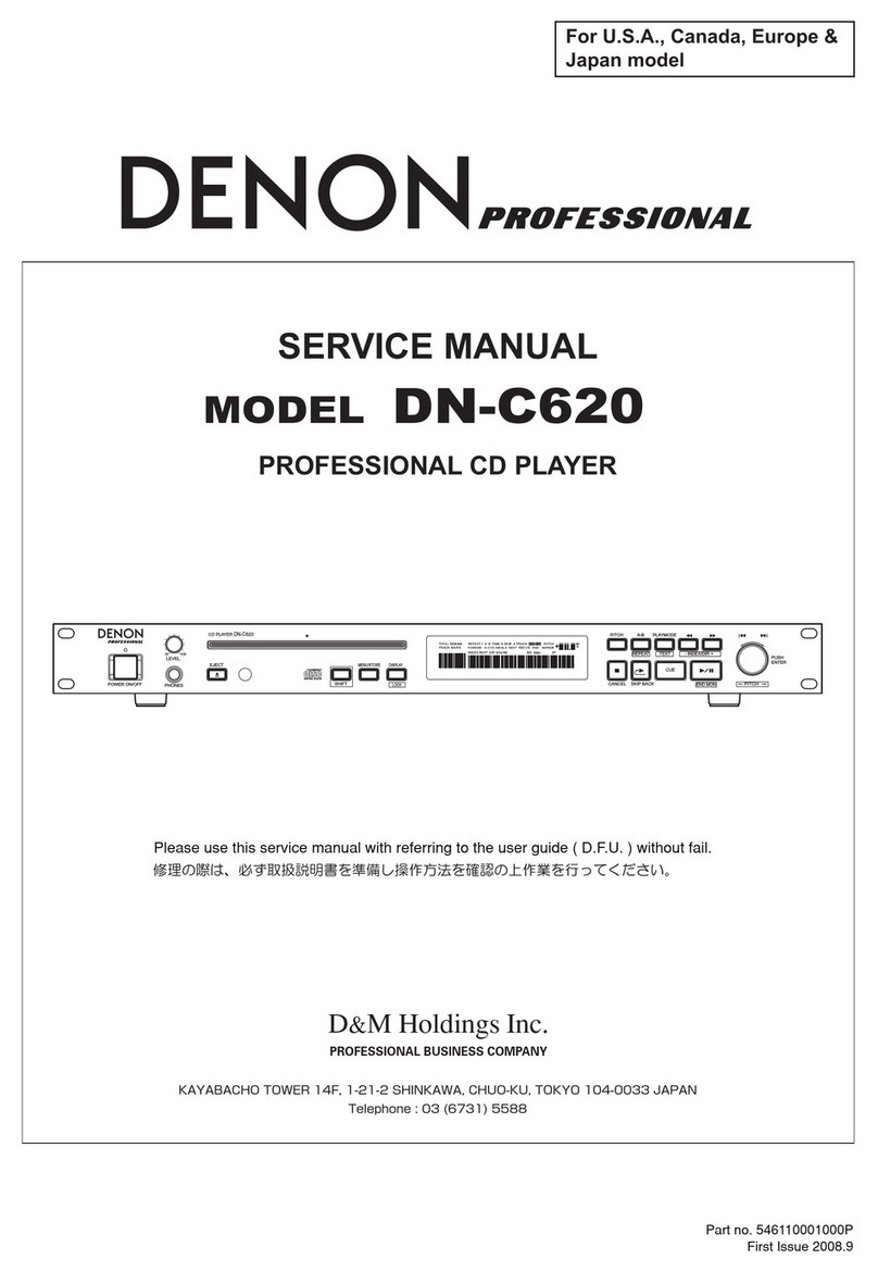
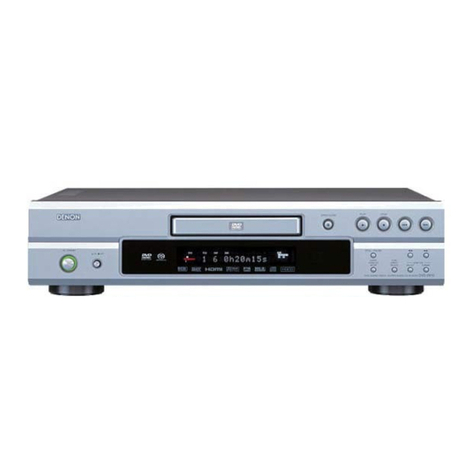
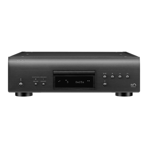
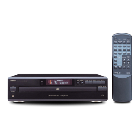
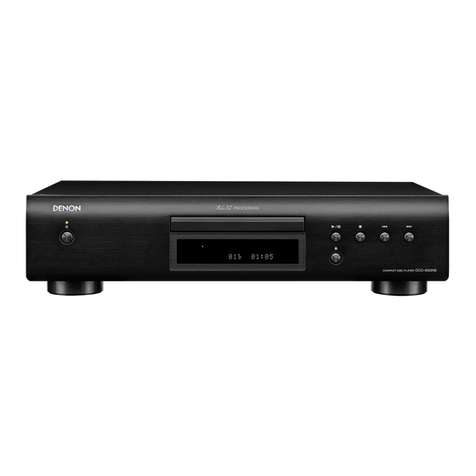
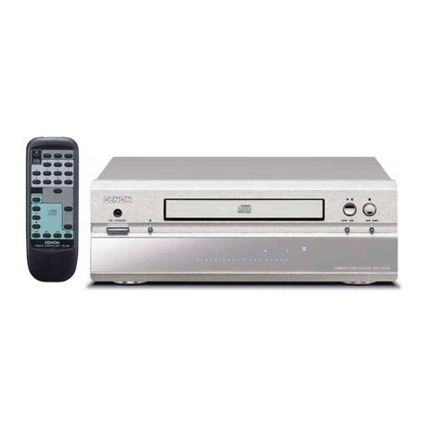
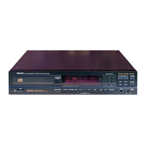
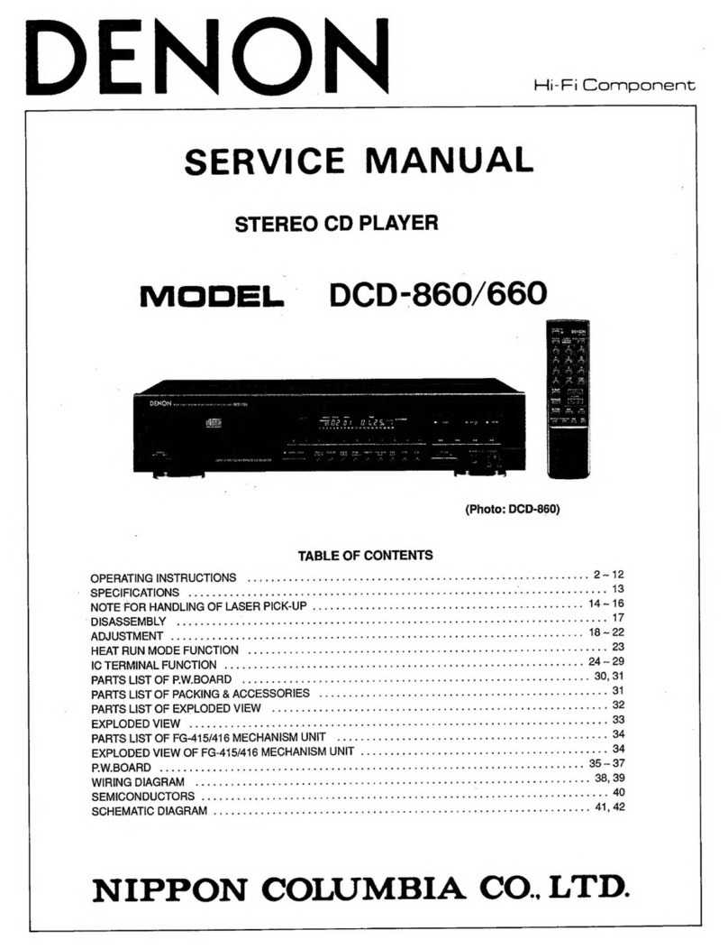
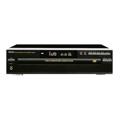
Denon DCD-315 User manual

ET
DENON
_......
SERVICE
MANUAL
MODEL
DCD-315
STEREO
CD
PLAYER
DENOWN
ecw
auoio
recunoroaricompactoscrtaven
DCD-315
Misic
—
TABLE
OF
CONTENTS
—
OPERATING
INSTRUCTIONS
........
0.6
ce
eee
eee
eben
ence
ee
enn
2~6
SPECIFICATIONS
bac
s.sisiSeiinn
ce
Searc'e
a
eeaaticanina
Setcacaneartcoehars
Neues
Bgus,
dreletweiaih
dg
ata
pu
aabie
a
bate
whee
wteneaers
Seen
7
DISASSEMBUN
3
5.
cfapst
tens
tora
ghiva
ees
OO
TREAT
UB
tne
tala
eWaretach
avid
o
daa,
Wh
ataealdare
aheeaghare
dations
8~9
CONFIRMING
METHOD
OF
SERVO
.....
0...
eee
ee te
eee
e
nee
e
nett
ene
eeeeenes
10~12
TEST
METHOD
FOR
HEAT
RUN
MODE
.....
02...
e
ete
teeta
ee
eeeerenaes
13
NOTE
FOR
HANDLING
OF
THE
LASER
PICK-UP
.........
0.0.0.
c
cece cece
ce
eect
e
nent
nee
e
ee
eees
14~18
SEMICONDUCTORS:
sicccicc
aos
ahberer
aie
eatin
fh
ab
didtag
ceded
DOE
Wr
ha
aavedrs
acetals
nd
Wullagania
dbo
19
~
24
NOTE
FOR
PARTS
LIST
i.¢
och
etic,
Heene
alg
ete
da
aie
oh
ee
bate
aha
Ben
be
eld
da Ga
an
tee
dacee
tees
25
PARTS
LIST
OF
PRINTED
WIRING
BOARD
...........-.
0.0
eect
cece
eee
e
tence
ennnens
26
~
27
PARTS
LIST
OF
CD
MECHANISM
UNIT
2.2.0...
eee
eee
e
ee
een
ennenennees
28
PRINTED
WIRING
BOARD
.........
ccc
ccc
ete
eee
teen
eee
e
eben
teen
sree
n
nena
neteuseeeas
29
WIRING
DIAGRAM
033.5
seca
eee
eae
Dk
ae
ene
aad
Wea
harwed
aed
ww
asa
bed
leigh
aw
we
eng
dia
Adee
dh
eelpnds
uel
30
PARTS
LIST
OF
EXPLODED
VIEW
.....
2...
ccc
ccc
ccc
cece
eee
ete
eect
eneneene
beens
30
PARTS
LIST
OF
PACKING
&
ACCESSORIES
.......
0.00.
occ
cece
eee
eenennennens
30
EXPLODED
VIEW
OF
CHASSIS
AND
CABINET
......
00.
n
nee
n
nent
nannies
31
EXPLODED
VIEW
OF CD
MECHANISM
UNIT
....
1.6...
cece
eet
eens
nenenenes
32
PARTS
LIST
OF
CD
MECHANISM
UNIT
...
0.0...
cc
eee
cece
eenennnenees
32
PARTS
LIST
OF
OPTICAL
PICK-UP
UNIT
.
2...
oo
ence
eee
rere
ee
ee
eee
eb
entteeeeeees
32
SCHEMATIC
DIAGRAM
a0.
ooo:c0.5
sce
ei
eee
liee
pee
ek
cue
de
eeu
weet
Handa
dg
odale
ne
baw
wanes
bales
33
NIPPON
COLUMBIA
CO.
LTD.

NOTE
ON
USE
/
HINWEISE
ZUM
GEBRAUCH
/
OBSERVATIONS
RELATIVES
A
L’UTILISATION
NOTE
SULL’USO
/
NOTAS
SOBRE
EL
USO
/
ALVORENS
TE
GEBRUIKEN
/
OBSERVERA
OBSERVACOES
SOBRE
O
USO
werden
sot,
Evher
des
températures
tlevees.
‘Tanit
compte
d'une
dispersion
de
chaleur
sulfsante
tors
de
linglaltation
sur
une
Evie
temperatures
alas.
Guange
intialer
0
equipementa,
numa
prateleira
coloque-o
de
modo
&
permitic
Uma
dlesipagto
suficiente
do
calor
Handte
the
power
cont
cavetuly,
‘Hold
tha
plug
when
unplugging
the
cord,
Gener
Bie
Yoreichug
mit
gem
Notzkebet
Hatten
Ste
das
Kabel
am
Stecker,
wen
Sie
8
aus
der
Steckdose
zlehen,
Manipuler
te
cordon
d'alimentation
avec
précaution.
‘Tenis
la
prime
lors
du
débranchement
du
cordon.
Maneggiare
con
cura
il
cave
di
ntazione.
‘Quando
8!
ecollega
hi
cavo
dalla
presa,
non
tare
I
cavo.
Manele
@!
cordén
de
slimentacion
con
guldado.
Somenge
ol
enchute
cuando
deeconecte
ig
Houd
het
snoer
by
de
stekker
vest
wannee!
deze
moet
worden
ast
of
leagekappeld.
Hartera
nitkabem
vera
Hittin
ru
rt
Dra
inte
5
kabain.
Manusale
0
cabo
de
alimentagso
com
‘cuidado.
‘Agave
na
fiche
para
dasligar
0
cabo
de
allmentagso
de
tomada.
‘apparaat
binnend
Ural
ine
agparaten
"or
Wut,
vaton
och
tina
easoarai
ivre
de
humidade
‘Agua
ou
pd,
|
apperaten.
Evite
delxar
objectos
estranhoe
sobre
o
aparelho.
Las
geen
woctuigheld,
water
of
stot
In
hat
Unplug
the
power
cord
whan
not
using
the
‘set
for
long
periods
of
time.
Ziahon
Sie
dea
Netzkabet
aus
der
Steckdo-
Sa,
worn
Be
dea
Geete
Ober
onan
Wngeren
Débrancherte
cordon
alimortatonorsaue
Fappareli
n'est
pee
willed
pendent
de
gues
péricdes,
Guano
etprevede
dl
eon
vlizzare
Funta
par
lunghl period
dl
tego,
delneerre
#
al
allmentazione
dala
press.
Saaconace
I
corgon
de
aimentacién
0
tice
@
equipo
por
mucho
tempo,
Near
ent
net
netnoer
uit
hel
wopoeakt
wanser
het
apparaa
gedurende
e6n
lange
perlode
niet
wordt
gebrulkt
Dra
ur
nitkontakien
om
apparaien
inte
kommer
pa
lange.
«
Desiigue
0
cabo
de
akmemteslo
quando
‘Abo
Utlizar
0
equlpamento
durante
periodos
prolongados.
(Oo
not
let
insecticides,
benzene,
and
thinner
‘come
in
contact
with
‘the
set
Latsen
Sie
daa
Geri
nicht
rit
insaidiziden,
benzenhattigen
oder
anderen
Verda:
in
BerOhrung
kommen.
fie
bas
metre
en
contact
Gos
wieecices,
du
benzéne
st
un
diluent
evec
l'appareil,
Evitare
di
utilizzare
Insetticidi,
benzolo
«
solvent!
sul
unite
Last
geen
ineekisnverdeigende
middelen,
ane
of
vertverdunner
met
dX
appersst
komen.
4a
kontakt
Se
til
at
inte
Insektemedel,
Densen
och
thinner
kommer
|
kontakt
med
apparatens
hoje.
Evite
que
Insecticides,
benzina
@
diivante
‘enirem
@m
contacto
com
0
equiparnento.
“(For
sete
with
ventilation
holes)
Do
not
obstruct
the
ventilation
holes.
Ole
Latungsechiiize
dirten
nicht
verdecket
werden.
Ne
pas
obstruer
tes
trous
d'aération,
Non
cstruire
i
fon
per
la
ventilazione.
No
tape
ian
ranuras
de
ventiackin.
De
veniliatioopaningen
mogen
niet
worden
Dablokkeerd.
‘Tapp
Inte
th
ventlationstppningsme.
Nébo
tape
v8
orificios
de
vertilagso.
bid
=
hig
r®
Never
disassemble
or
modity
the
eet
in
any
way.
Versuchan
Sie
niemals,
das
Gertt
seib-
S1Andig
aussinanderzunehmen
oder
aut
jagiche
Art
2u
verandem.
Ne
Jamals
démenter
ou
modifier
l'appareil
une
maniéve
ou
une
autre
Nan
gmontare
o
madiicare
In
alcun
mode
Tuna.
Nance
desare
0
endive
4!
squco
de
alogne
Noon
31
appereat
demonteren
of
op
andere
wie
medion.
Ta
Inte
lads
apparaten
ooh
torabk
inte
byggs
om
den.
Nunea
deemonte
ou
modiique
0
equips-
manto
de
alguma
forms.
FRONT
PANEL
VORDERSEITE
PANNEAU
AVANT
PANEL
ANTERIOR
VOORPANEEL
FRONT
PANELEN
DISPLAY
ANZEIGE
AFFICHAGE
DISPLAY
VISUALIZADOR
DISPLAY
DISPLAYEN
MOSTRADOR
REAR
PANEL
RUCKWAND
PANNEAU
ARRIERE
PANNELLO
POSTERIORE
Mo
Aa
oo
Litt
Ct
itw
Lt
Ls
A.SPACE
TOTAL
EMPHASIS.
PLA)
SINGLE
UPAUSE
|
REPEAT
A-B
PROG
@
PANEL
POSTERIOR
ACHTERPANEEL
BAKSIDAN
PAINEL
TRASEIRO
IMPORTANT
TO
SAFETY
NOTE:
WARNING:
This
CD
player
uses
the
semiconductor
taser.
To
allow
you
to
enjoy
music
ata
stable
operation,
itis
recommended
to
use
this
in
a
room
of
5
°C
(41
°F)
TO
PREVENT
FIRE
OR
SHOCK
HAZARD,
DO
NOT
EXPOSE
THIS
=
35
°C
(95
°F).
APPLIANCE
TO
RAIN
OR
MOISTURE.
¢
NUR
FUR
EUROPAISCHE
MODELLE
Konformitatserklérung
Die
DENON
Elektronik
GmbH
Haiskestr.
32
40880
Ratingen
erklart
als
Hersteller/mporteur,
daB
das
in
dieser
Bedienungsanleitung
beschriebene
Gert
den
Technischen
Vorschriften
fOr
Ton-
und
Femseh-
Rundtunkempfanger
nach
der
Amtsbiattverfigung
868/1989
(Amtsblatt
des
Bundesministers
fiir
Post
und
Telekommunikation
vom
31.86.1989)
entspricht.
y
eS)
PANNELLO
FRONTALE
PAINEL
FRONTAL
~~
ee
“ome
x
IN
rca
ss00
reemonoareounc
ri
De
net
lat
foreign
ables
inte
sat
Lasaen
Sie
keinenel
Gegensiiinde
in
das
us
j
+
Keep
the
set
free
trom
moleture,
water
and
Gehduneinnere
eindringen.
|
dual.
Ne
‘pas
tmover
dpe
cote
@oangert.
care
‘Janid
Nigh
tempecanres
*
eseor
Uae
‘Staus
nm,
oes
Ne
cadere
oggetto
alia
anser
ul
te
‘Alow
tor
sufficient
heat
dispersion
when
+
Protéger
apparell
contre
Fhumidilé,
Peau
crt
se
\egtatled
on
a
rack.
at
ta
poussidre.
No
Inserte
abjatos
extrafioe
en
#/
equipo.
Vermaiden
Sie
hohe
Temparaturen.
.
Reaceanare
ith
ities
tan,
ecqua
Laat
geen
vreemde
voorwerpen
In
dit
lek.
lstet
sein
mul
.
q
fl
teremd
Lutlkuiaton
gewahneltet
sein
mus,
Weer
oa
ied
agua
Se
oi
att
fh
I
inte
trfinger
In

Thank
you
for
purchasing
this
DENON
Compact
Disc
Player.
Please
read
the
operating
instructions
thoroughly
in
order
to
acquaint
yourself
with
the
CD
player
and
achieve
maximum
satisfaction
from
it.
—
TABLE
OF
CONTENTS
—
FEATURES
....
CONNECTION
THE
COMPACT
DISK
NAMES
AND
FUNCTIONS
OF
PARTS
OPENING
AND
CLOSING
THE
DISC
HOLDER
AND
LOADING
A
DISC...
NORMAL
CD
PLAYBACK
.
ADVANCED
CD
PLAYBACK
ADVANCED
FUNCTION
..
TIMER-CONTROLLED
PLAYBACK
..
_
PLAYBACK
USING
THE
REMOTE
CONTROL
UNIT
INSTALLATION
PRECAUTIONS
.
TROUBLESHOOTING
SPECIFICATIONS
....
Please
check
to
make
sure
the
following
items
are
included
with
the
main
unit
In
the
carton:
(1)
Operating
instructions
(2)
Connection
Cord
(3)
AC
Cord
FEATURES
The
DCD-315
includes
a
mutti-noise
shaping
D/A
converter
which
has
a
built-in
high
performance
digital
filter.
This
assures
accurate
reproduction
of
the
digital
signals
recorded
on
compact
discs
no
matter
whether
they
are
pure
studio
recordings
or
“live”
performance
recordings.
All
parts
making
up
this
CD
player
have
selected
with
the
greatest
care
in
order
to
produce
high
quality
realistic
playback
of
the
full
musical
content
on
compact
discs.
(1)
Multi-Level
Noise
Shaping
D/A
Converter
The
newly
developed
multi-noise
shaping
system
is
employed
in
the
D/A
converter
to
contro!
distortion
and
to
permit
rich
sound
Playback.
(2)
High
Performance
Digital
Fitter
The
DCD315
uses
a
highly
accurate
8
times
oversampling
digital
filter
to
achieve
characteristics
equal
to
those
of
the
optimum
analogue
fitter.
This
permits
clear
and
vivid
playback.
(3)
Remote
Sensor
Aremote
sensoris
builtin,
so
ifthe
remote
control
unit
for
DENON’s
receivers
and
amplifiers
or
a
separately
purchased
remote
contro!
unit
(RC-241)
is
used,
the
DCD-315
can
be
operated
from
the
optimum
listening
position.
The
remote
control
unit,
of
course,
includes
play,
stop,
and
pause
functions,
butis
also
capable
of
such
functions
as
direct
selection
and
direct
programming.
CONNECTION
(1)
Connecting
the
Output
Terminal
(LINE
OUT)
Use
the
included
pin
cords
to
connect
the
left
(L)
and
right
(R)
output
terminal
(LINE
OUT)
of
the
DCD-315
to
the
CD
or
AUX
or
TAPE
PLAY
left
(L)
and
right
(R)
input
jacks
of
the
amplifier.
DCO-315
Power
outiet
i
Amplifier
AK
Connection
Precautions
°
—
Before
proceeding
with
connections
or
disconnections
of
cables
and
power
cords,
be
sure
to
tum
all
system
components
off.
*
—
Ensure
thatall
cables
are
connected
properly
tothe
L
(left)
and
R
(right)
jacks.
*
Insert
plugs
fulty
into
the
terminals.
*
Connect
the
output
jacks
to
the
amplifier
CD,
AUX
or
TAPE
PLAY
input
jacks.
THE
COMPACT
DISC
1.
Precautions
on
handling
compact
discs.
Do
not
allow
fingerprints,
oi!
or
dust
on
the
surface
of
the
compact
disc.
ifthe
signal
surface
is
dirty,
wipe
it
off
with
a
soft,
dry
cloth.
Wipe
in
circular
motions
from
the
center
and
out.
°
—Donotuse
water,
benzene,
thinner,
record
sprays,
electrostatic
Proof
chemicals,
or
silicone-treated
cloth
to
clean
discs.
*
Always
use
care
when
handling
discs
to
prevent
damaging
the
surface,
in
particular
when
removing
a
disc
from
the
case
and
retuming
it.
Do
not
bend
compact
discs.
Do
not
apply
heat
to
compact
discs.
Do
not
enlarge
the
hole
in
the
center
of
the
disc.
Do
not
write
on
the
disc
and
do
not
attach
any
labels.
Condensation
will
form
on
the
disc
surface
if
itis
brought
into
a
warm
room
from
a
cold
area,
such
as
outdoors
during
winter.
Wait
until
the
condensation
disappears.
Never
dry
discs
with
hair
dryers,
etc.
2
Precautions
on
storage
After
playing
a
disc,
always
retum
it
to
its
case.
*
Keep
discsin
the
cases
when
they
are not
to
be
played.
This
will
protect
them
from
dust
and
dist
and
prolong
their
service
life.
*
Donat
store discs
in
the
following
places:
1)
Places
exposed
to
direct
sunlight
for
a
considerabie
time.
2)
Places
subject
to
accumulation
of
dust
or
high
humidity.
3)
Places
exposed
to
high
temperatures,
such
as
close
to
heater
outlets.
NAMES
AND
FUNCTIONS
OF
PARTS
(Refer
to
page
3.)
FRONT
PANEL
@»
Power
Switch
(POWER)
When
the
power
is
turned
on,
“(00)”
appears
on
the
TRACK
NO.
display.
«
Wheneverthe
power
switchis
in
the
OFF
state,
the
apparatus
is
stil
connected
on
AC
line
voltage.
Please
be
sure
to
unplug
the
cord
when
you
leave
home
for,
Say,
a
vacation.
Disc
Holder
°
Load
a
disc
here.
Open/Close
Button
(4
OPEN/CLOSE)
*
The
disc
holder
is
opened
and
closed
by
pressing
this
button.
*
Press
this
button
once
to
open
the
disc
holder,
and
once
again
to
close
it.
@
Remote
Contro!
Sensor
(REMOTE SENSOR)
*
—
This
sensor
receives
the
infrared
light
transmitted
from
the
wireless
remote
control
unit.
¢
—
For
remote
control,
point
the
DENON’s
remote
control
unit
towards
this
sensor.
*
When
a
signal
is
transmitted
from
the
remote
control
unit,
the
remote
control
indicator
in
the
display
@
will
fight
up
briefty.
@
Play
Button
(>
PLAY)
*¢
—
Press
this
button
to
start
playing
the
disc.
*
Even when
the
disc
tray
is
open,
the
disc tray
closes
and
playback
begins
when
this
button
is
pressed.
Stop
Button
(@
STOP)
*
Press
this
button
to
stop
playback.
@
Pause
Button
(Il
PAUSE)
*
Press
this
button
to
stop
playback
temporarily.
¢
Press
this
button
or
the
play
button
(>
PLAY)
again
to
continue
playback.
©
Number
Buttons
(1,
2,
3,
4,
5, 6,
7,
8,
9
and
10)
«¢
Usethese
buttons
for the
direct
search
and
program
memory
functions.
©
+10
Button
(+10)
*
Press
this
button
first
when
selecting
track
numbers
over
10.
Use
it
together
with
the
number
buttons
@.
@
144\<4
(automatic/manuai
search
reverse)
button
Use
this
tomove
to
the
beginning
of
a
specific
track.
When
pressed
during
playback
orin
the
pause
mode,
the
pickup
moves
backward
a
number
of
tracks
equal
to
the
number
of
times
the
button
is
pressed.
@
_
>>>
(automatic/manual
search
forward)
button
Use
this
to
move
to
the
beginning
of
a
specific
track.
When
pressed
during
playback
or
in
the
pause
mode,
the
pickup
moves
forward
a.
number
of
tracks
equal
to
the
number
of
times
the
button
is
pressed.
*
Theautomatic
search
mode
is
set
if
the
K44\44
or b>
/
PPibutton
is
released
within
0.5
seconds,
and
the
manual
search
mode
is
set
if
the
button
is
held
for
over
0.5
seconds.
@
FUNCTION
Button
«
—
Use
this
button
to
select
progranydirect,
repeat,
auto
space,
time
display
and
auto
edit
function.
(Refer
to
page
8,
9
for
details.)
®
Enter
Button
*
—
Use
this
button
to
set
the
progranvdirect,
repeat,
auto
space,
time
display
and
auto
edit
functions
selected
with
the
FUNCTION
button.
(Refer
to
page
8,
9
for
details.)
DISPLAY
Track
Number
Indicator
Playback
Time
Indicator
20-Track
Music
Calendar
Auto
Space
Indicator
Emphasis
Indicator
Play
Indicator
Remaining
Time
of
Entire
Disc
Pause
indicator
Remaining
Time
of
Current
Track
All
Repeat
indicator
A-B8
Repeat
Indicator
Program
Indicator
Remote
Contro!
indicator
REAR
PANEL
@
Output
Terminal
(LINE
OUT)
©
Connect
these
jacks
to
the
input
jacks
on
your
amplifier.
(Refer
to
page
4
for
details
on
the
connections.)
@
AciINLET
¢
—
Connect
the
included
AC
cord
here.
Continuous
Button
Operation
Ifthe
+10
button
@,
the
automatic/manual
search
reverse
button
@
or
the
automatic/manual
search
forward
button
@
are
held
in
function
of
that
button
will
be
repeated.
22
8b
60
aaa
a
ae
a
ay

OPENING
AND
CLOSING
THE
DISC
HOLDER
AND
LOADING
A
DISC
Opening
and
closing
the
disc
hokder
(This
operation
only
works
while
the
power
is
on.)
1.
Press
the
power
switch
(POWER)
to
tum
on
the
power.
2.
Press
the
open/close
button
(4
OPEN/CLOSE).
How
to
load
a
disc
«
—
Make
sure
the
disc
holder
is
completely
open.
*
—
Hokdthe
disc
by
the
edges
and
place
it
on
the
disc
tray.
(Do
nottouch
the
signal
surface,
i.e.,
the
glossy
side.)
*
When
using
12
cm
diameter
discs,
make
sure
the
outer
edge
matches
the
tray
guide
circumference
(Fig.
1),
and
when
using
CD
singles
(8
cm
diameter),
match
the
outer
edge
with
the
inner
tray
guide
circumference
(Fig.
2).
*
Press
the
open/close
button
(4
OPEN/CLOSE)
to
close
the
disc
holder.
*
When
the
disc
holder
is
closed,
the
disc
is
read
and
after
a
few
seconds
the
number
of
tracks
and
tatal
playing
time
are
displayed
on
the
TRACK
NO. and
TIME
displays,
respectively.
«
—
When
the
dischotderis
open anda
discis
joaded,
you may
atso
press
the
play
(>
PLAY)
or
pause
(§&
PAUSE)
button
to
close
the disc
holder.
(H
the
play
button
(>
PLAY)
is
pressed,
playback
will
start
immediatety
upon
the
disc
contents
having
been
read.)
Fig.
1
Tray
guide
for
12
cm
disc
Caution:
¢
—
Ifyourfinger
should
get
caught
in
the
disc
holder
when
it
closes,
press
the
open/close
button
(4
OPEN/CLOSE).
*
Donot
place
any
foreign
objects
on
the
disc
tray,
and
do
not
place
More
than
one
disc
on
the
tray
ata
time.
Otherwise
malfunction
may
occur,
*
Do
not
push
in
the
disc
tray
manually
when
the
power
is
off
as
this
may
cause
'matfunction
and
damage
the
CD
player.
NORMAL
CDPLAYBACK
(1)
Starting
Playback
1.
Press
the
power
switch
(POWER)
to
tum
on
the
power.
.
Load
the
disc
you
want
to
play.
*
—
When
the
disc
holder
is
closed,
the
disc
is
read
and
the
number
of
tracks
and
total
playing
time
of
the
disc
aré
displayed.
3.
Press
the
play
button
(>
PLAY).
(2)
Stopping
Playback
(BsTOP)
1.
Press
the
stop
button
(J
STOP).
«
When
ail
tracks
have
been
played
on
a
disc,
playback
will
stop
by
itself.
Precautions:
*
—
{fno
disc
has
been
loaded
or
the
disc
has
been
placed
upside
down,
altindicators
will
light.
*
When
the
information
on
the
disc
cannot
be
read
correctly,
for
example
due
to
dust
or
dirt
on
the
disc,
the
indicators
will
read
as
shown
below.
Nothing
will
be
shown
on
the
TRACK
NO.
and
TIME
displays,
and
it
may
take
quite
a
while
to
read
the
disc.
ADVANCED
CDPLAYBACK
@
Playing
a
Specific
Track
.......
(Number
buttons)
*
Usethenumber
buttons
and
the
+10
button
to
input
the
number
of
the
desired
track.
For
exampie,
to
play
track
number
4,
press
[4],
andto
play
track
number
12,
press
[+10}
and
[2].
Playback
will
begin
from
that
track.
@
Advancing
to
the
next
track
uring
playback
.-eccersrneensenneneenseet
Press
the
Automatic
search
forward
button
(b>/
Ppt)
during
playback,
and
it
should
be
released
within
0.5
seconds.
*
—
The
pickup
will
advance
to
the
beginning
of
the
next
track
and
Playback
will
continue.
Pressing
the
button
several
times
will
forward
the
pickup
the
corresponding
number
tracks.
@
Returning
to
the
beginning
of
the
current
track
during
playback
............|
Automatic
Search
|
(2)
Manual
Search
in
Reverse
Press
the
manual
search
reverse
button
(I44\44)
during
playback
in
for
more
than
0.5
seconds.
Reverse
playback
of
the
track
is
sped
up.
Asareference,
the
current
track
number
and
elapsed
piayback
time
within
the
track
are
displayed.
Manual
search
in
reverse
is
approximately
three
times
faster
when
engaged
during
the
pause
state
compared
toplayback.
In
this
case,
no
sound
is
heard,
however.
Hthe
manual
search
reverse
bution
(I44\44)
is
kept
pressed
after
the
beginning
of
the
first
track
on
the
disc
is
reached,
(£0)
is
disptayed
and
manual
search
stops.
To
retum
to
another
point,
press
the
manual
search
forward
button
(>>/
PPI)
until
(CC)
disappears.
(H44\
44)
Press
the
Automatic
search
reverse
button
(44
\44)
during
playback,
and
it
should
be
released
within
0.5
seconds.
¢
—
The
pickup
will
retum
to
the
beginning
of
the
current
track
and
playback
will
continue.
Pressing
the
button
several
times
will
return
the
pickup
the
corresponding
number
tracks.
@
*
Using
this
function,
you can cue
to
a
desired
point
within
a
track,
either
in
the
forward
or
reverse
direction.
*
Release
the
manual
search
button
(H44\4¢
oF
D/P)
when
the
desired
point
has
been
reached.
Normal!
playback
then
continues.
{1)
Manual
Search
Forward
(tN
PAUSE)
Playback
can
be
temporarily
halted
and
then
continued
from
the
same
point
in
the
track.
Press
the
pause
button
(lB
PAUSE)
during
the
playback.
Tocontinue
playback,
press
the
play
button
(>
PLAY)
or
the
pause
button
(1
PAUSE)
once
more.
Searching
and
Pausing
at
the
Beginning
With
Direct
Search
In
this
case,
the
set
pauses
at
the
beginning
of
the
track found
with
the
direct
search
operation.
1.
Pressthe
manual
search
forward
button
(b>/
PP)
during
playback
in
for
more than
0.5
seconds.
Playback
of
the
track
is
sped
up.
¢
—
Asareference,
the
current
track
number
and
elapsed
playback
time
within
the
track
are
displayed.
*
Manual
search
forward
is
approximately
three
times
faster
when
engaged
during
the
pause
state
compared
to
playback.
In
this
case,
no
sound
is
heard
however.
*
_
ifthe
manual
search
forward
button
(p>/
b>)
is
kept
pressed
afterthe
end
of
the
final track
on
the
disc
is
reached,
(3)
is
displayed
and
manual
search
stops.
To
retum
to
another
point,
press
the
manual
search
reverse
button
(H44\4@)
until
(33)
disappears.
(2)
(Number
buttons)
(U8PAUSE)
Press
the
number
button
@
for
the
desired
track.
Prass
the
(§—
PAUSE)
button.
To
start
playback,
press
the
(>
PLAY)
or
(Wl
PAUSE)
button.
With
Program
Search
Press
the
(18
PAUSE)
button
after
the
program
search
operation
is
completed.
The set
will
pause
at
the
beginning
of
the
first
programmed
track.
a
a
a
S.-C)
maa

ADVANCED
FUNCTION
The
[FONCTION]
and
[ENTER
]
buttons
may
be
used
to
perform
the
following
advanced
functions.
Adifferent
function
in
the
following
cycle
may
be
accessed
eachtime
the
button
is
pressed:
Programming
——*
Repeating
playback
al
LL
Auto
space
———»
Time
mode
——»
Auto
edit
7
Aftarthe
respective
functions
have
been
accessed
via
the
[
FUNCTION
]
‘button,
press
the
[ENTER
]button
to
operate
the
respective
functions.
(FUNCTION
Button)
(ENTER
Button)
Time
mode
is
effective
only
during
play
and
pause.
Auto
edit
is
effective
onty
during
stop.
Playing
Specific
Tracks
ina
Specific
Order
...........
Programmed
Play
With
this
function,
you can
choose
any
of
the
tracks
on
the
disc
and
Program
them
to
play
in
any
order.
Programming
is
possible
with
the
disc
holder
open.
Up
to
20
tracks
can
be
programmed.
The
programmed
tracks
are
shown
on
the
calendar.
2)
Press
the
[FUNCTION
]button
to
display
“Func01”
on
the
TRACK
NO.
and
TIME
display,
The
“PROG”
indicator
blinks
when
the
last
mode
was
normal
playback
mode.
Press
the
button
within
four
seconds
after
“Func01”
has
been
accessed
to
set
the
programming
function,
and
the
"PROG"
indicator
will
light.
Then
use
the
number
buttons
and the
+10
button
to
program
the
tracks.
For
example,
to
program
tracks
3,
12
and
7,
press
[3],
[+10],
[2)and
[7].
The
corresponding
track
number
light
on
the
calendar
each
time
a
track
is
programmed,
the
track
number
is
displayed
on
the
TRACK
NO.
display,
and the
total
playing
time
of
the
programmed
tracks
is
displayed
on
the
TIME
display.
A
few
seconds
after
the
last
track
has
been
programmed,
the
total
number
of
tracks
programmed
is
displayed
on
the
TRACK
NO.
display
and
the
total
playing
time
of
the
programmed
tracks
is
displayed
on
the
TIME
display.
Playing
the
Programmed
Tracks
Press
the
(>
PLAY)
button
to
play
the
tracks
in
the
programmed
order.
(3)
Clearing
the
Program
Press
the
[FUNCTION
|
button
to
display
“Func01”
on
the
TRACK
NO.
and
TIME
display.
The
"PROG"
indicator
will
light.
Press
the
button
within
four
seconds,
and
the
“PROG*
indicator
will
btink.
Four
seconds
after“Func01”
lights,
"PROG"
goes.
out,
and
the
program
is
cleared.
The
program
is
also
cleared
when
the
button
is
pressed.
When
the
program
has
been
cleared
during
programmed
play,
playback
will
continue
from
the
track
presently
being
played
back
to
the
last
track.
NOTES
*
—
Ifprogrammingis
done
in
the
play
or
pause
mode,
the
track
currently
playing
is
programmed
at
the
first
position.
Other
tracks
can
be
added
to
the
program,
but
the
number
of
Programmed
tracks
and
the
playing
time
will
not
be
displayed.
*
Direct
search
is
not
possible
during
programmed
play.
If
the
number
buttons
are
pressed,
that
track
is
added
tothe
end
of
the
program.
*
Programming
is
possible
with
the
disc
holder
open.
Track
numbers
greater
than
the
number
of
tracks
recorded
onthe
disc
can
be
programmed,
but
will
be
automatically
cleared
before
playback
begins.
©
—
The
remaining
time
per
track
will
only
be
displayed
fortrack
numbers
1
through
20.
*
—
Thetotal
program
time
and
remaining
program
time
are
not
displayed
if
tracks
greater
than
track
number
20
are
programmed.
*
During
the
four
seconds
in
which
“Func01”
is
iit,
the
[ENTER
|
button
can
be
used
to
altemately
select
Accept
Programming
Mode
and
normal
playback.
a)
Repeating
Playback
nvesnsnsmmnuntstmernmeneenren
ROPORt
|
Repeating
Playback
Press
the
[FUNCTION
]button
to
display
“Func02”
on
the
TRACK
NO.
and
TIME
display.
The
“REPEAT
indicator
blinks
when
the
last
mode
was
normal
playback
mode.
Press
the
button
within
four
seconds
after
“Func02"
has
been
accessed
to
set
the
repeat
function,
and
the
“REPEAT”
indicator
will
ight.
button.
Playback
of
all
tracks
are
repeated.
Repeating
playback
may
also
be
set
during
playback.
‘When
the
repeat
function
has
been
set
during
programmed
playback,
Playback
of
the
programmed
track
is
repeated.
(2)
(1)
Canceling
repeating
playback
Press
the
[FUNCTION
]button
to
display
“Func02”
onthe
TRACK
NO.
and
TIME
display.
The
“REPEAT
indicator
will
light.
The
“REPEAT”
indicator
blinks
when
the
button
is
pressed
within
four
seconds.
Four
seconds
after
“Func02"
lights,
“REPEAT
goes
out,
and
repeating
playback
is
canceled.
During
the
four
seconds
in
which
“Func02”is
lit,
the
button
can
be
used
to
aitemately
select
Accept
Repeating
Playback
Mode
and
norma!
playback.
This
is
a
convenient
feature
that
will
insert
4-second
bianks
between
tracks,
which
can
be
used
when
recording
compact
discs
on
tape.
Auto
Space
Press
the
[FUNCTION
]button
to
display
“Func03”
on
the
TRACK
NO.
and
TIME
display.
The
“A.SPACE*
indicator
blinks
when
the
last
mode
was
normal
Playback
mode.
Press
the
[ENTER
]
button
within
four
seconds
after
“Func03”
has
been
accessed
to
set
the
Auto
Space
function,
and
the
“A.SPACE"
indicator
will
light.
Then
press
the
button.
Canceling
Auto
Space
Press
the
[FUNCTION
Jbutton
to
display
“Func03”
on
the
TRACK
NO.
and
TIME
display.
The
“A.SPACE"
indicator
will
light.
Press
the
[ENTER
|
button
within
four
seconds,
and
the
“A.SPACE*
indicator
will
blink.
Four
seconds
after
“Func03"
lights,
"A.SPACE*
goes
out,
and
Auto
Space
is
canceled.
During
the
four
seconds
in
which
"Func03"
is
fit,
the
button
can
be
used
to
altemately
select
whether
or
not
Accept
Auto
Space
is
effective.
Although
4-second
blanks
are
inserted
between
tracks,
this
additional
time
is
not
reflected
by
the
indication
on
the
time
remaining
display
or
time
display
when
the
Auto
Edit
function
is
engaged.
Time
Mode
This
function
is
used
to
select
the
desired
indication
on
the
TIME
display.
The
indication
on
this
display
will
change
each
time
the
functionis
chosen.
Normally,
the
elapsed
playback
time
of
the
current
track
is
displayed.
When
SINGLE
is
displayed,
the
remaining
time
of
the
current
track
is
displayed.
When
TOTAL
is
displayed,
total
playing
time
of
remaining
tracks
is
displayed.
However,
when
programmed
play
is
in
progress,
the
total
remaining
time
of
the
program
is
displayed.
a)
()
Time
Mode
Selection
Press
the
[FUNCTION
|buttonto
display
“Func04”
on
the
TRACK
NO.
and
TIME
display.
If
the
fast
mode
was
“normal”,
the
“SINGLE”
indicator
will
blink.
When
in
"SINGLE"
mode,
the
"SINGLE"
indicator
tights.
When
in
"TOTAL"
mode,
the
"TOTAL"
indicator
lights.
Press
the
button
within
four
seconds
after
“Func04”
has
been
accessed
to
select
functions
in
the
cycle
"SINGLE*
"TOTAL"
normal.
“SINGLE"
mode
is
in
effect
when
the
"SINGLE®
indicator
fights.
"TOTAL"
mode
is in
effect
when
the
"TOTAL
indicator
lights.
Normal
mode
is in
effect
when
neither
“SINGLE*
nor
“TOTAL
"lights.
["
SINGLE
——»
TOTAL
-—~
normal
|
Auto
Edit
The
tracks
ona
CD
are
automaticatly
split
into
two
halves,
Side
A
and
Side
B,
like
an
analog
disc,
with
the
division
at
the
place
between
tracks
whichis
closest
to
1/2
the
total
playing
time,
and
with
the
tracks
remaining
in
the
same
order.
Setting
Auto
Edit
Press
the
[FUNCTION
|button
to
display
“FuncEd”
on
the
TRACK
NO.
and
TIME
display.
Press
the
button
within
four
seconds
after
“FuncEd”
is
accessed
to
set
the
Auto
Edit
function.
The
total
playing
time
for the
first
half
and
the
track
numbers
on
the
calendar
are
displayed
for
approximatoly
2
seconds.
Next,
the
same
is
done
for the
second
half,
after
which
the
unit
is
automatically
set
tothe
pause
mode
at
the
beginning
of
the
first
track.
When
the[
PLAY
]
or
[PAUSE
]
button
is
pressed,
playback
begins,
and
the
unit
is
automatically
set
to
the
pause
mode
at
the
beginning
of
the
first
track
ofthe
second
halt
which
was
previously
displayed.
When
the|
or[_PAUSE_]
button
is
pressed
again,
playback
begins,
and
the
unit
is
automatically
set
to
the
stop mode
at
the
end
of
the
last
track
on
the
disc.
This
function
will
only
work
for
discs
with
a
total
of
20
tracks
or
less.
Also,
when
this
function
is
used
the
mode
is
automatically
set
to
the
Program
mode,
so
direct
search
is
not
possible.
The
auto
edit
function
is
cleared
when
the[_SToP_]buttonis
pressed.
The
data
for
the
total
playing
time
recorded
on
the
disc
and the
actual
total
playing
time
of
the
tracks
differ,
so
there
may
be
a
difference
between
the
time
displayed
in
the
stop
mode
(the
total
playing
time)
and
the
total
of
the
times
of
the
first
and
second
halves
in
the
auto
edit
mode
(about
2
seconds).
aa
aa
a
a

TIMER-CONTROLLED
PLAYBACK
@
=
Operation
1.
Tumon
the
power
of
all
system
components.
2.
Setthe
input
selector
on
the
amplifier
to
correspond
to
the
inputs
the
CO
player
is
connected
to.
3.
Make
sure
a
disc
has
been
loaded
in
the
disc
holder.
4.
Clack
the
time
on
the
timer
and
then
set
the
desired
tum-on
time.
5.
Tumthe
audio
timer
ON.
Poweris
turned
off
automatically
in
all
components
connected
to
the
timer.
6.
When
the
preset
turn-on
time
is
reached,
power
is
tumed
on
in
the
system
components,
and
CD
playback
starts
form
the
first
track.
Power
supply
outiet
PLAYBACK
USING
THE
REMOTE
CONTROL
UNIT
If
the
remote
control
for
Denon
receivers
and
amplifiers
or
a
separately
purchased
remote
contro!
unit
(RC241)
is
used,
the
DCD315
can
be
Operated
from
the
optimum
listening
position.
(1)
Inserting
the
dry
cell
batteries
1.
Remove
the
battery
cover
on
thie
back
of
the
remote
control
unit.
2.
_
Insert
dry
cell
batteries
with
correct
polarity
as
indicated
inside
the
battery
compartment.
3.
Replace
the
battery
cover.
10
Notes
on
the
Batteries
*
-
The
remote
control
unit
uses
standard
size
AA
dry
cell
batteries.
*
The
batteries
will
need
to
be
replaced
approximately
once
a
year.
Replacement
may
be
necessary
earlier
depending
on
how
much
the
remote
control
unit
is
used.
«
—
If,
in
less
than
a
year from
the
time
new
batteries
were
inserted,
the
remote
control
fails
to
operate
the
CD
player
from
a
near-by
position,
it
is
time
to
replace
the
batteries.
*
—
Insertthe
batteries
property,
following
the
polarity
diagram
inside
the
battery
compartment,
in
other
words
make
sure
(+)
and{-)
terminals
are
properly
aligned.
*
Batteries
are
prone
to
damage
and
leakage.
Therefore:
*
Donot
combine
new
batteries
with
used
ones.
*¢
Donot
combine
different
types
of
batteries.
*
Donot
jumper
opposite
poles
of
the
batteries,
expose
them
to
heat,
break
them
open
nor
expose
of
them
in
open
fire.
*
—
Ifthe
remote
control
unit
is
not
to
be
used
for
a
long
period
of
time,
remove
the
batteries
from
the
unit.
*
Ifthe
batteries
have
leaked,
remove
any
traces
of
battery
fluid
from
the
battery
compartment,
wiping
thoroughly
with
a
dry
cloth.
Then
insert
new
batteries.
(2)
Directions
for
Use
«
Operate
the
remote
contro}
unit
while
pointing
it
towards
the
remote
control
sensor
on
the
CD
player
(see
below).
When
a
remote
contro!
signal
is
received,
the
remote
contro}
indicator
on
front
of
the
CD
player
lights
briefly.
*
The
remote
control
unit
can
be
used
at
a
distance
up
to
8
meters
in
astraightline
from
the
CD
player.
This
distance
decreases
if
there
are
obstructions
blocking
the
signal
path
or
when
the
remote
control
unit
is
operated
at
an
angle
from
the
remote
control
sensor.
*
The
buttons
on
the
remote
contro!
unit
have
identical
functions
with
those
on
the
CD
player.
However,
the
following
functions
cannot
be
remote
controlled:
Power
ON/OFF.
Do
not
press
identical
buttons
on
the
CD
player
and
remote
control
unit
simultaneously
as
this
may
cause
malfunction.
*
—
Theremote
control
unit
may
be
difficult
to
operate
if
the
remote
contro!
sensoris
exposed
to
strong
light,
such
as
direct
sunlight
or
light
from
fluorescent
lamps,
or
if
there
are
obstacles
between
the
remote
control
unit
and
the
sensor.
*
Direct
track
selection
Using
the
track
number
buttons
(1
~
10,
+10),
tracks
can
be
directly
assigned
for
playback.
*
Track
selection
while
programming
Press
the
program
button
(PROG)
and
then
the
track
numbers
you
wish
to
enter
into
the
memory.
Example:
PROG
+ 3
+
+104
135...
(Tracks
3,
11,5
and
so on
are
entered
into
the
memory.)
Memorized
tracks
are
erased
by
pressing
the
Direct
button
(DIRECT).
*
Correct
use
of
the
track
number
buttons
Direct
selection
of
single-digit
tracks
is
easy
by
just
pressing
the
desired
track
number
button.
For
tracks
with
numbers
trom
114
andon,
first
press
the
+10
button
and
then
a
single-digit
button.
E.9.,
toselect
track
22,
press
the
+10
button
twice
and
then
press
the
2
button.
INSTALLATION
PRECAUTIONS
The
CO
player
uses
a
microcomputer
for
controlling
internal
electronic
circuits.
In
the
event
that
the
player
is
used
while
a
near-by
tuner
or
TV
is
tumed
on,
although
unlikely,
interference
could
occur
either
inthe
sound
from
the
tuner
or
the
picture
of
the
TV.
To
avoid
this,
please
take
the
following
precautions:
*
Keepthe
CD
player
as
far
away
from
the
tuner
or
TV
set
as
possible.
*
Keep
the
power
cable
and
connecting
cable
of
the
CD
player
separate
from
the
antenna
wires
of
the
tuner
and
TV.
¢
—
Interference
is
particular
likely
to
occur
when
an
indoor
antennaora
300-ohm
feeder
cable
is
used. Thus,
use
of
an
outdoor
antenna
and
75-ohm
coaxial
cable
is
strongly
recommended.
TROUBLESHOOTING
tf
the
CD
player
does
not
seem
to
be
functioning
properly,
check
the
following:
Disc
holder
does
not
open
or
close.
*¢
—
Is
the
power
on?
When
a
disc
Is
loaded,
00
00
00
is
displayed.
*
ts
the
disc
loaded
property?
.
See
page
6
When
the
play
button
(>
PLAY)
is
pressed,
playback
does.
not
start.
*
Is
the
disc
dirty
or
scratched?
.
See
page
4
There
is no
sound,
or
It
is
distorted.
¢
—
Is
the
output
cord
property
connected
to
the
amplifier
aoe
cresresseeeee
SOE
page
4
*
—
Have
the
amplifier
controls
been
set
correctly?
SS
300-ohm
feeder
cable
75-ohm
coaxial
cable
A
specific
section
of
the
disc
will
not
play.
*
—
Is
the disc
dirty
or
scratched?
Programmed
playback
does
not
work.
¢
Have
programming
been
property
done?
...........
....
See
pages
8,
10
Incorrect
operation
when
buttons
on
the
remote
control
are
pressed.
*
_
Isthe
remote
control
unit
being
operated
too
far
from
the
CD
player?
....
ache
soagaleasel
¢
Are
there
obstacles
blocking
the
ray?
*
—
Is
the
remote
control
sensor
exposed
to
strong
light?
°
—
Are
the
batteries
exhausted?
.
See
page
4
11
Sr
a
a
ea
a
a
eee!
ILE
-OOC]
Raa

aE
es
ICD-315
ae
SPECIFICATIONS
AUDIO
FUNCTIONS
AND
DISPLAY
No.
of
Channels:
2
channels
Functions:
Automatic
search,
programmed
Frequency
Response:
2
~
20,000
Hz
playback,
repeat
playback,
Dynamic
Range:
95
dB
manual
search,
auto
space,
Signal-to-noise
Ratio:
104
dB
time
mode,
auto
edit
Harmonic
Distortion:
0.004%
(1
kHz)
Display:
Track
number,
time,
music
calendar,
Separation:
93
dB
(1
kHz)
emphasis
feature
and
engaged
modes
Wow
&
Flutter:
Below
measurable
limit:
(+0.001%
W.peak)
Output
Voltage:
2.0V
DISCS
Compact
Disc
format
GENERAL
CHARACTERISTICS
Power
Supply:
50
Hz,
~
230
V
Power
Consumption:
10
W
Dimensions:
434
(17-3/32")
W
x
105
(4-1/
8")
H
x
279
(11-1/32")
D
mm
Weight:
3.5
kg
*Design
and
specifications
are
subject
to
change
without
notice
in
the
course
of
product
improvement.

[mg
OCD-315
DISASSEMBLY
1.
LOADER
PANEL
As
removing
front
panel
in
power
OFF
status,
use
a
screw
driver
to
insert
set
Loader
panel
below
hole
and
rotate
counterclockwise
@,
pull
out
disc
table
@,
then
detach
®
Pull
out
disc
table
Loader
panel
©.
@
Remove
Loader
panel
as
show
as
arrow
*
Keep
the
set
horizontally.
2.
TOP
COVER
1.
Remove
a
push
rivet
@.
(Europe
model:
last
four
figures
of
Ser.
No.
0001~06000)
Remove
a
screws
@.
(Europe
model:
last
four
figures
of
Ser.
No.
06001
and
after)
(U.K
model:
last
four
figures
of
Ser.
No.
0001
and
after)
2.
Remove
4
screws
©.

DCD-315
Zz
3.
FRONT
PANEL
1.
Remove
2
screws
©
and
undo
hooks
at
3
places.
2.
Remove
2
screws
@
.
4.
REAR
PANEL
1.
Remove
2
screws
@).
2.
Remove
2
screws
©.
3.
Remove
2
screws
©.

I
CONFIRMING
METHOD
OF
SERVO
A
microcomputer
adopted
to
this
unit
has
the
service
programs
so as
to
perform
confirming
more
easily
with
the
operation
buttons.
Digital
servo
adopted
to
this
unit
is
became
automatic
adjustment
status
in
focus
gain
and
tracking
gain.
1.
Actuating
the
Service
Program
(1)
Press
disc
holder
button,
turn
power
switch
OFF.
(2)
Shortcircuit
the
main
unit
CN505
pint
(SWOP)
to
pin3
(GND).
Note:
don’t
touch
another
connector
pin.
(3)
Turn
power
switch
ON.
(Service
program
start
actuates
and
displays
track
No.
ai
)
Note:
The
operation
buttons
do
not
function
when
service
program
actuates.
2.
Operation
Function
at
Service
Program
Actuation
Goeraton
Operation
Function
Explanation
4
OPEN/CLOSE
|
Opens
or
closes
disc
holder
button.
@
Open
or
closes
only
when
disc
is
stopped.
@
Operate
other
keys
after
open
or
close.
Mi
stop
Stops
system
function.
@
Displays
track
number
g
i.
@
Press
when
adjustment
completed
or
do
it
again.
p>
PLAY
Starts
Focus
servo
and
disc
turns.
@
Press
when
tracking
adjustment.
@
When
completed,
displays
track
number
a
Pad
.
Ii
PAUSE
Starts
Focus
servo,
Tracking
servo,
Slide
|
@
Pressing
PLAY
button,
starts
Tracking
servo
and
slide
servo.
servo
and
Spindle
servo.
@
When
completed,
displays
track
number
HH
3
,
Displays
a
result
of
Focus
gain
automatic
|
@
After
completed
PAUSE
operation,
pressing
Button
1
of
10-key
adjustment.
indicates
a
result
of
Focus
gain
automatic
adjustment.
Other
Buttons
@
When
completed,
Display
shows:
(Caution)
TRACK
TIME
e
During
the
service
program
is
in
operation,
do
not
use
remote
control.
=
vv
vv
t
AANHAAS
TIME
display
shows
automatic
adjustment
value.
:
n
4
Displays:
Uf
ne
5s~OOne
iS
or
EE:
is
@
After
completed
PAUSE
operation,
pressing
Button
2
of
10-cey
indicates
a
result
of
Tracking
gain
automatic
adjustment.
@
When
completed,
Display
shows:
TRACK
TIME
-
VV
Vv
e
KXnXXs
TIME
display
shows
automatic
adjustment
value.
‘
n
7
Displays:
us
ine
Ss
~8E28
isor
EEnWe:
@
Never
attempt
to
operate
the
buttons
other
than
the
above.
@
If
the
buttons
are
erroneously
pressed, promptly
turn
OFF
te
power
switch.
Displays
a
result
of
Tracking
gain
automatic
adjustment.
Unable
to
obtain
normal
function.
10

Sa
a
a
TS
een
OCD-315
aa
3.
Confirming
Method
(1)
Required
Measuring
Equipment
1)
Dual-trace
oscilloscope
2)
Test
disc:
CA-1094
(2)
Check
Point
CD
Mechanical
unit
PWB
(pattern
view)
(3)
Confirming
Procedure
1)
Actuate
the
service
program.
2)
Check
the
value
of
Focus
gain
automatic
adjustment.
3)
Check
the
value
of
Tracking
gain
automatic
adjustment.
4)
Check
for
Tracking
offset.
5)
Finish
the
service
program
and
return
the
mode
to
normal
operation
(turn
ON
the
power
switch
in
normal
manner).
6)
Check
for
HF
level.
(4
—
Confirming
Focus
Gain
1)
Press
button.
(Track
No.
indication
G3
)
2)
Press
button.
(Track
No.
indication
{-
)
3)
Check
for
automatic
adjustment
value.
Automatic
adjustment
value:
00m@82s
~
00M34s
(normal
temperature)
(Test
disc:
CA-1094)
01m04s
~
00m28s
(0°C~40°C)
Note:
As
itis
a
possibility
of
abnormality
in
pick-up
when
automatic
adjustment
value
is
EEm01s
or
less
than
00m27s,
execute
the
confirmation
for
pick-up
according
to
pick-up
replacement
standard.
if
there
is
no
abnormality
in
pick-up
as
described
in
pick-up
replacement
standard
notes,
no
problem
will
occur
for
disc
playback
even
though
the
automatic
adjustment
value
is
EEm01s
or
less
than
00m27s.
(5)
Confirming
Tracking
Gain
1)
Press
button.
(Track
No.
indication
g
3
)
2)
Press
button.
(Track
No.
indication
c-)
3)
Check
for
automatic
adjustment
value.
Automatic
adjustment
value:
00m81s
~
00m23s
(normal
temperature)
(Test
disc:
CA-1094)
01M03s
~
00M18s
(0°C~40°C)
Note:
As
itis
a
possibility
of
abnormality
in
pick-up
when
automatic
adjustment
value
is
EEm02s
or
less
than
00m22s
,
execute
the
confirmation
for
pick-up
according
to
pick-up
replacement
standard.
If
there
is
no
abnormality
in
pick-up
as
described
in
pick-up
replacement
standard
notes,
no
problem
will
occur
for
disc
playback
even
though
the
automatic
adjustment
value
is
EEm02s
or
less
than
00M22s
.
11

2M
OCD-315
(6)
Confirming
Tracking
offset
(E/F
Balance)
Connection
CD
Mech.
Unit
Oscilloscope
(Oscilloscope)
_
Push
|
OPEN/CLOSE
]
button
and
load
disc
holder
referrence
disk.
2.
Push|
4
OPEN/CLOSE
|
button
and
close
disc
holder.
0.1v/div
3.
Push
|
®
PLAY]
button
to
turn
disc.
(Displays
track
number
§¢
)
4.
Short
(+)(—)
of
oscilloscope
and
check
the
base
line.
5.
Confirm
that
upper
and
lower
amplitude
of
the
waveform
is
symmetric
against
OV.
(7)
Confirming
HF
Level
Connection
CD
Mech.
Unit
(RFO)
TP
O
50mvidiv
0.2us/div
or
or
20mVidiv
0.5u:s/div
A=1.54~0.85V
©
Sét
input
mode
to
ALTERNATE
or
CHOPPER.
_
FR\\\EE
Peete
ele
eeeny
Oscilloscope
.
Push}
Il
PAUSE}
button.
(Displays
track
number
83
)
.
Check
HF
level
of
oscilloscope.
.
Confirm
that
the
waveform
is
in
gor
shape.
(eye
pattern
in
center
must
be
able
to
discriminate
clearly.)

ae
a
a
ee
OCO-315
fas
TEST
METHOD
FOR
HEAT
RUN
MODE
1.
Actuate
While
hold
pushing
>
,
6
and
7
buttons
simultaneously,
turn
the
unit
power
on.
The
remote
control
sensor
indicator
will
light
to
show
that
the
unit
is
shifted
in
Heat
Run
mode.
Press
the
button
to
cancel
Heat
Run
mode
after
loading
disc.
2.
Operation
1)
Heat
Run
test
During
the
Heat
Run
mode
to
start
in
Play
mode,
it
makes
the
unit
replays
from
the
first
track
after
opens
the
loader
when
finishing
with
playing
last
track.
After
that,
this
operation
is
over
again.
When
disc
has
over
21
tracks,
makes
the
unit
to
search
the
last
track
and
set
operation
times.
2)
Chucking
test
Press|PAUSE
|
button
2
times
in
the
Heat
Run
mode,
it
makes
the
unit
opens
the
loader,
turns
the
servo
ON,
reads
out
TOC,
operates
first
track
search
and
does
over
again.
3)
Sound
out
test
During
the
Heat
Run
mode,
press
+10
button
to
start
in
Play
mode.
If
it
generates
over
+
8
frame
sound
out,
stop
the
operate
and
display
the
error
message.
3.
Error
Message
When
the
system
error
occurs
in
the
Heat
Run
mode,
display
the
error
message
with
TRACK
and
operated
times
with
TIME.
1)
E1
error
Focus Servo
does
not
activate.
2)
E2
error
GFS
does
not
drive.
3)
E3
eroor
No
GFS
emit.
4)
E4
error
TOC
is
unreadable.
5)
E5
error
Does
not
turn
the
Loader
switch
ON.
6)
E6
error
Does
not
turn
the
Pick-up
inner
circle
switch
OFF.
7)
E7
error
Does
not
turn
the
Pick-up
inner
circle
switch
ON.
8)
E8
error
Sound
out.
13

ES
OC
O-
3
15
a
a
NOTE
FOR
HANDING
OF
THE
LASER
PICK
UP
Judgement
standards
for
PICK-UP
Replacement
14
1.
PICK-UP
REPLACEMENT
The
pick-up(PU)
replacement
must
be
executed
upon
the
following
4
items
and
found
the
abnormality
in
the
PU.
When
PU
is
abnormal,
please
write
PU
abnormality
cause
for
PU
sign
column
of
connecting
prompt
report
of
market
quality
state
clearly.
1)
Judgement
by
confirming
of
Focus
search
(cause
of
PU
abnormality:
Focus
search
does
not
function.)
2)
Judgement
by
checking
of
changing
PU
due
to
Focus
error
signal
Vre
(cause
of
PU
abnormality:
No
proper
emission
of
focus
error
signal
(s-curve)
VFE)
3)
Judgement
by
checking
of
changing
PU
due
to
Tracking
Error
signal
Vre
(cause
of
PU
abnormality:
No
proper
emission
of
tracking
error
signal
(traverse
waveform)
VTE)
4)
Judgement
by
checking
of
changing
PU
due
to
HF
level
Vir
(cause
of
PU
abnormality:
No
proper
emission
of
HF
waveform)
.
DISC
TO
BE
USED
FOR
CONFIRMATION
Using
disc:
No.
CA-1094
.
OTHER
CAUSE
OF
PU
CHANGING
Ifit
happened
other
cause
of
PU
replacement
except
the
above-mentioned
4
items,
please
execute
PU
replacement
and
write
this
cause
for
connecting
prompt
report
of
market
quality
state
in
detail.

1.
Judgement
by
Confirming
of
Focus
Search
(Check
for
focus
search
function
of
PU
Lens)
Actuate
the
service
program.(service
mode)
Press[PLAY]
button
without
loading
the
disc.
Does
PU
lens
move
up
/
down?
Yes
Load
the
adjustment
disc.
Press
button.
Perform
continuous
focus
search.
(Note
1)
Trouble
may
exist
in
defection
other
than
PU.
Cause
of
defection:
1.ls
inner
Switch
OK?
2.1s
loading
Switch
OK?
3.Is
slide
functioning?
4.ls
any
melting
trace
found
around
PU
lens?
(If
yes,
this
is
caused
by
other
defection,
require
PU
replacement.)
Check
for
1
thru
4,
etc.
Confirm
that
the
connector
cable
is
properly
inserted.
Does
FOK
signal
turned
"L"
to
"H"?
Does
FOK
signal
turned
"L"
to
"H"?
Trouble
may
exist
in
PU
abnormality
due
to
FOK.
Execute
PU
replacement.
(FOK
NG)
Perform
checking
of
item
2.
(Next
page)
Note
1:
Press|PLAY]
button
continually
in
FOK
measuring.
DcoD-315
HZ!
15

RS
COS
75
a
a
a
a
ee
a
2.
Judgement
by
checking
of
changing
PU
due
to
Focus
Error
signal
Vre
(check
for
proper
S-surve)
Load
the
adjustment
disc
(CA-1094).
(Note
1)
(service
mode)
S-curve
wave
Press[PLAY]button.
Perform
continuous
focus
search.
(Note
2)
[0.5V/div]
GND
Observe
with
oscilloscope
across
test
point
FE
and
VC.
[2msec/div]
Record
VrEmax
data
with
maesuring
focus
error
signal
(S-curve)
3
times.
Is
VFEmax
shown
more
than
1.58V?
Is
PU
lens
cleaned?
Yes
Clean
the
PU
lens.
(Note
3)
Record
Vremax
data
with
measuring
VFE
signal
10
times
by
turn
disc
about
approx.
90°.
Trouble
may
exist
in
PU
abnormality
due
to
focus
error
signal
(S-curve)
VFE.
Execute
PU
replacement.
Perform
checking
of
item
3.
(Next
page)
Note
1:
Adjustment
disc
(CO-76143)
VFE
=
1.67
V.
Note
2:
Press
button
continually
in
VFeE
measuring.
Note
3:
Gently
wipe
out
the
lens
surface
with
a
little
amount
of
isopropyl
alcohol
soaked
lens
cleaning
paper
without
apply
excessive
force
to
the
lens.
16

3.
Judgement
by
checking
of
changing
PU
due
to
(check
for
proper
Traverse
waveform)
Actuate
the
service
program.
(service
mode)
Load
the
adjustment
disc.
(CA-1094)
(Note
1)
Press[PLAY]button,
and
display
Be.
(focus
search
only
ON)
Observe
with
oscilloscope
across
test
point
TE
and
VC.
Measure
tracking
error
signal.
No
ls
VTEmax
shown
more
than
0.64V?
Yes
Is
VTE
signal
continuously
shown?
Yes
Perform
checking
item
4.
(Next
page)
Note
1:
Adjustment
disc
(CO-76143)
VTE
=
0.70
V.
Is
PU
lens
cleaned?
DCcD-315
laa”
Tracking
Error
Signal
VTE
1.
Tracking
error
signal
level
without
undulation.
Traverse
waveform
[0.5V
/
div]
Haif
turn
of
disc
pool
AT
Thin
Thick
Thin[2msec/div]
VTE
2.
Tracking
error
signal
level
with
undulation.
UML
A
3.
Occasionally
no
tracking
error
signal
level.
atl
Maal
MMA
aa
TN
Aa
Thin
Thick
Thin
[2msec/div]
[0.5V
/
div]
Vie
(2msec/div])
[Defective
PU]
GND
VTE
No
Clean
the
PU
lens.
Trouble
may
exist
in
PU
abnormality
due
to
VTE.
Execute
PU
replacement.
17

ge
DCD-315
4.
Judgement
by
checking
of
changing
PU
due
to
HF
level
Vir
(check
for
proper
HF
waveform)
Actuate
the
service
program.
(service
mode)
HF
waveform
[0.2V/div]
Load
the
adjustment
disc
(CA-1094),
(Note
1)
Press|PAUSE]button,
and
playback
disc.
(display
G3
)
VHF
GND
[0.5y/div]
Observe
with
oscilloscope
across
test
point
RFO
and
VC.
Measure
RFO
level
VHF
signal
No
Is
VHF
shown
more
than
0.85V
Yes
No
Is
PU
lens
cleaned?
Yes
Clean
the
PU
lens.
signal.
Execute
PU
replacement.
No
abnormality
in
PU.
PU
abnormality
due
to
VHF
Note
1:
Adjustment
disc
(CO-76143)
VHF
=
0.85
V.
18

DCcD-315
HZ
SEMICONDUCTORS
@
IC's
BA6297AFP
fale
ino
<x
MN
[ep
NN
ice)
<<
faa)
s
T.S.D;
thermal
short
down
D;
driver
buffer
BA6297AFP
Terminal
Function
Pt
|
[©
[GH
output
terminal).
Es
ae
ESellies
aa]
Os
cs
7
ee
Be
Fs
an
ee
nee
|
GNo
|__|
Vret-Amplifier
and
constant
current
ground.
_
a
he
ae
ee
mae
Eos
am
Eon
ieee
Be
|
GN
|
7
cc
Note:
Each
driver
output
polarity
is
reference
to
Pre-Amplifier
output
terminal
polarity
(+).
11
j15{
|
jie]
Par
jie|
PIO
ac
j2o]
|
21
|
Veo
_|
|
22|
Veo
_|
j23|
pee
j25]
|
j26]
Ec
[26
|
GND
|
19

CXD2515Q
CXD2515Q
Terminal
Function
|
PinNo.
|
Symbol
|
vo
fo
Function
|
1
—|
~~
SRON
|
O
[Sleddriveoutputsignal.
—
C—“‘“‘(‘((CN”COC*C*#*#C(#‘*C
|
2
|
SRDR
|
O
|Sleddriveoutputsignal.
=
CC“‘“‘(CSSCOCOC*#C#C#C(C(‘zdC
|
3
|
SFON
|
O
|Sleddriveoutputsignal.
=
C—“‘“‘(‘CSC*C*C*C*‘*@CY
|
4
|
TFDR
|
O
|Trackingdriveoutputsignal.
—
C“‘“‘(‘“CSNCO”*CO*#C*C*C*C*#C*C#*#C*‘*C
|
5
|
TRON
|
O
|Trackingdriveoutputsignal.
CS
|
6
|
TRDR
|
O_|
Tracking
drive
output
signal.
|
7
|
TFON
|
©
_|
Tracking
drive
output
signal.
|
8
|
FFOR
|
©
|Focusdriveoutputsignal.
=
s—“‘CSCO*C*C*C*;*C‘*dC
|
9
|
FRON
|
O
|Focusdriveoutputsignal.
==
—“‘“‘CSCO™COCOC*;C*‘*C
|
10
|
FRDR
|
O
|[Focusdriveoutputsignal.
ss
C(C‘C‘isdCS
|
11
|
FFON
|
O
[Focusdriveoutputsignal.
|
12
|
vcoo
|
O
[Osc.
circuitoutputforanalogEFMPLL.
Cd
|
13
|
~~
vcol_—|_—t=<([
Ose.
circuitoutputforanalog
EFMPLL.
CS
|
14
[|
Test
|
1
|Testterminal,normallyGND.
C—C“‘“‘CCCCidC
|
15
|
~—DVss_—
|
—
[Digitalground
—
C—“‘“CS*S*S*S*S*S™S”:S:SCSSCSCSCSC‘SC*d
|
16
|
TeES2_
|
1
[TestterminalnormallyGND.
C“‘CSC‘*dC
|
17
|
TES3_
|
1
[Testterminal,normallyGND.
|
18
|
PDO
|
©
[ChargepumpoutputforanalogEFMPLL.
|
19
|
veco
|
©
[Pltchargepumpoutputforvariablepitch,
|
20
|
vcKi_
|
1
[Clockinputfromexternal
VCO
forvariablepitth,
Cd
|
21
[AvD2
||,
~—
|
Analog
power
supply.
|
22
|
IGEN
|
1
|PowersupplyterminalforOP
amplifier.
=
|
23
[|
avs2
|
—
|Analogground
ss
—“‘CSCSC*™*™*™*™*C*C*C*C*C*™*C*C™C*C™*™S™S*SC~C*~CSCSC‘zC
|
24
{|
abil__—[_1
[A/Dconverterinputterminal.
|
25)
|
ADIO,
=|
~O
[OP
amplifieroutputterminl.
|
26
[
RFOC
|
|
|[AFsignalinpu.
Ss
—C—“‘“‘“‘“CSOCSOCCCOCOCOCOC*#C‘(YTNCNNNC(‘édz
|
27
|
TE
|_|
|Trackingerrorsignalinput,
—CCi“‘“CS™SCOOCOC*C‘*zC
|
28
|
Se
|
|
[Slederorsignalinput.
—
C“‘“‘“CSCSC™C™C™*C*C‘isC
|
29
|
~FE
|=
~=([Focuserrorsignalinput.
—Ci‘“‘CSCSC‘*C
|
30
|
vc
|
1
[Middlepointvoltage
inputtermian.
Cd
|
31
[FILO
|
O
|FilteroutputformasterPLL.
C‘“‘“C;CS™SC*C*C*‘*C
|
32
[Ful
dT
tt
[FilterinputformasterPLL.
CC“‘“CSCSC‘idC
|
_33
|
PCO
|
0
[Charge
pump
output
for
master
PLL.
|
34
|
citv__|
1
[VCOcontrolvoltageinputformaster.
Cd
|
35
[|
avsi
|
—
[Analogground,
—CSOCC“‘“(‘#$SNN’NNCC‘dCS
|
36
=|
RAC.
|
I
[eFMsignalinpt
=
—SSCSC“‘“‘(“$NNC‘édC
|
37
{BIAS
|
1
|Asymmetrycircuitconstantcurrentoutpu.
|
3a
[
ASyi__|
1
|Asymmetrycomparatorvoltageinput.
|
39
~[
~ASYo.
|
O
|[EFMfullswngauput
=
C—“—s™SsSs—C“‘“‘“‘“SC(‘#éC’
|
40_|
Avo
|
—
[Analogpowersuppy.
SS
—CSCSSCSC“‘SSNSSCC
20
Other Denon CD Player manuals

Denon
Denon DCD-1520AE User manual

Denon
Denon DN-C635 User manual

Denon
Denon DCD-1600NE User manual

Denon
Denon DVM-745 Instruction Manual

Denon
Denon DCD-1520 User manual

Denon
Denon DCM-290 User manual

Denon
Denon DND6000 - Dual DJ CD Player User manual

Denon
Denon DN S5000 - DJ Table Top Single CD Player User manual

Denon
Denon DCD-1650R User manual

Denon
Denon DVD-3930 User manual

Denon
Denon DVD-A1XV User manual

Denon
Denon DN-D9000 User manual

Denon
Denon DCT-950R User manual

Denon
Denon DCM 290 - CD / MP3 Changer Instruction Manual

Denon
Denon DCD-500AE User manual

Denon
Denon DVM-745 User manual

Denon
Denon DCD-F101 User manual

Denon
Denon DVM-1835 - DVD Changer User manual

Denon
Denon DCD-510AE User manual

Denon
Denon DN-D4000 User manual