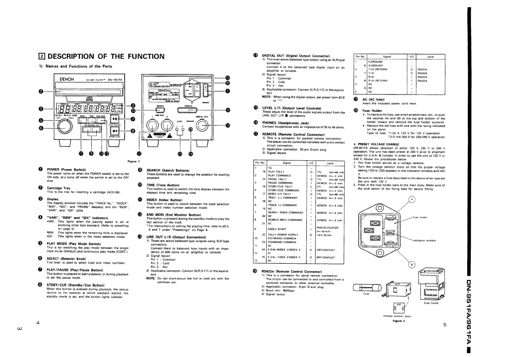
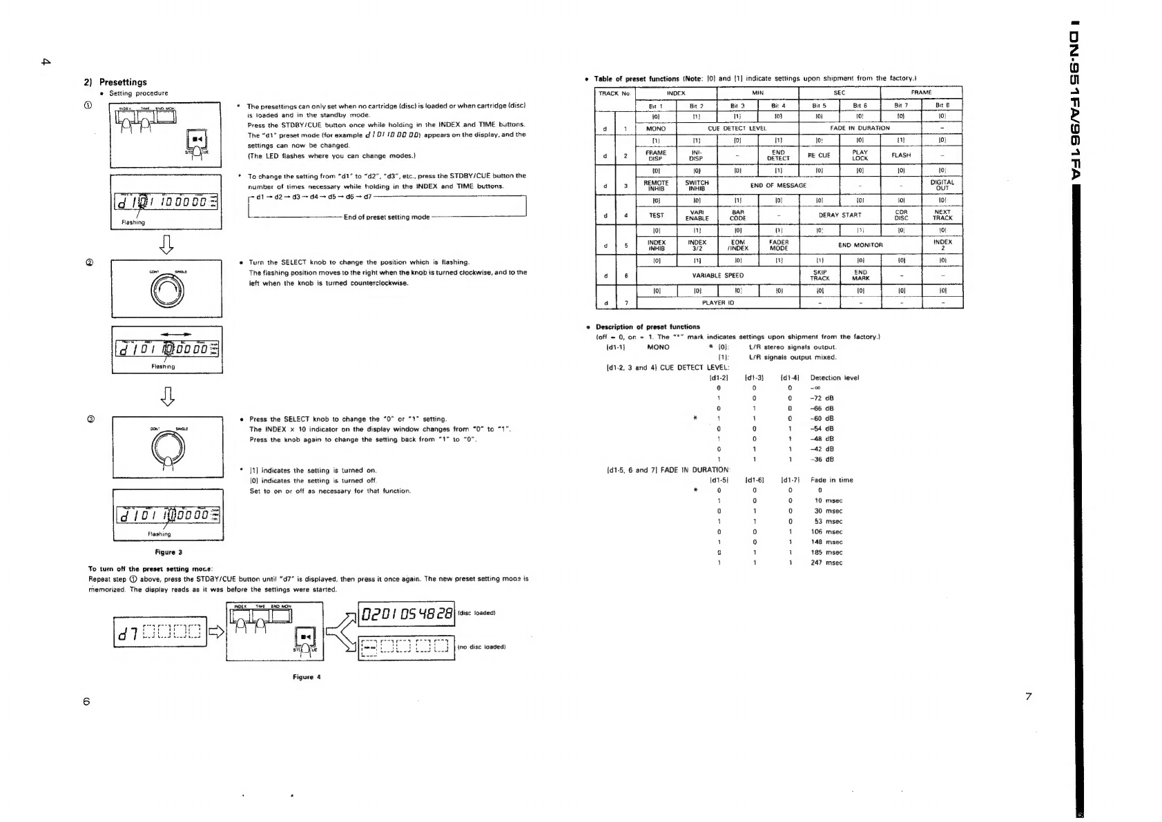
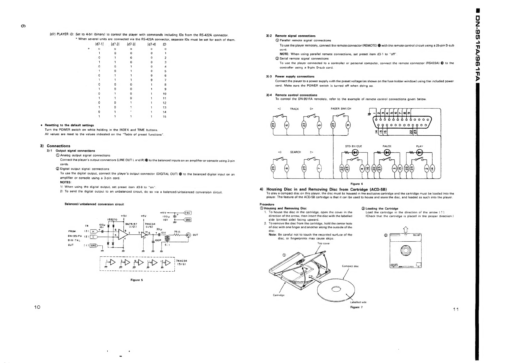
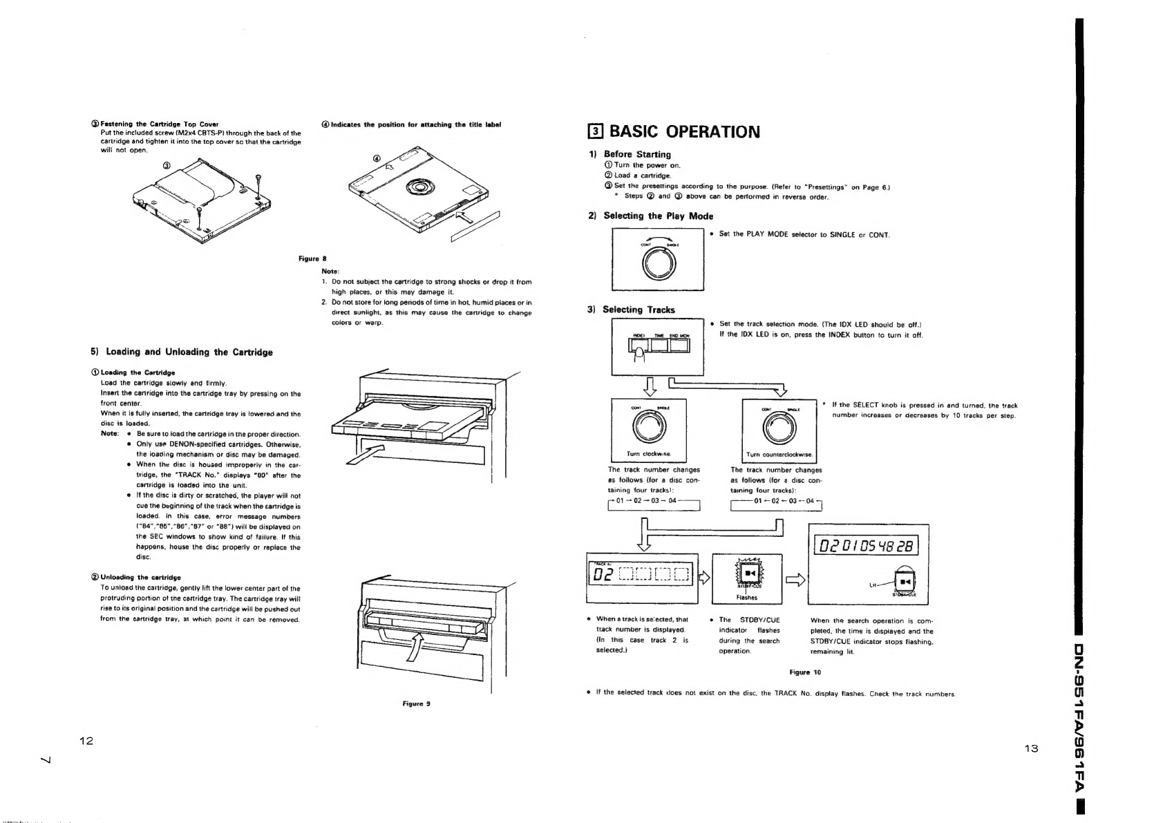
Denon DN-951FA User manual
Other Denon CD Player manuals

Denon
Denon DVM-745 User guide

Denon
Denon DCD-1520AE User manual

Denon
Denon DCD-425 User manual

Denon
Denon DN-C635 User manual

Denon
Denon DN-S3000 User manual

Denon
Denon DN-300C User manual

Denon
Denon DN-2700F User manual

Denon
Denon DCD-F109 User manual

Denon
Denon DCD-900NE User manual

Denon
Denon DCD-F101 User manual

Denon
Denon DCD-1500 User manual

Denon
Denon DCD-2000AE User manual

Denon
Denon DN-S700 - Compact Tabletop CD/MP3 Disc... Installation and operation manual

Denon
Denon DCM-500AE User manual

Denon
Denon DN-C640 - Slot-In Network CD Player User manual

Denon
Denon DVM-2845CI User manual

Denon
Denon DCD-810 User manual

Denon
Denon S1000 - DN Scratch DJ Table Top CD User manual

Denon
Denon DCD-485 User manual

Denon
Denon DCD-F107 User manual