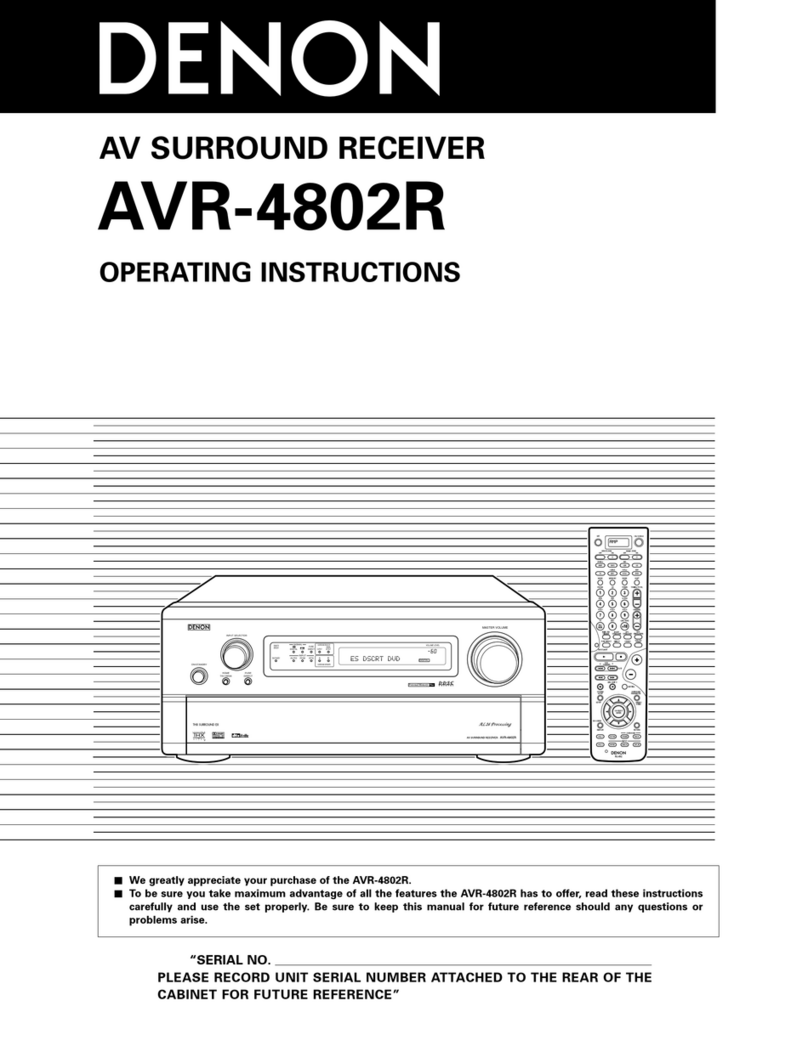
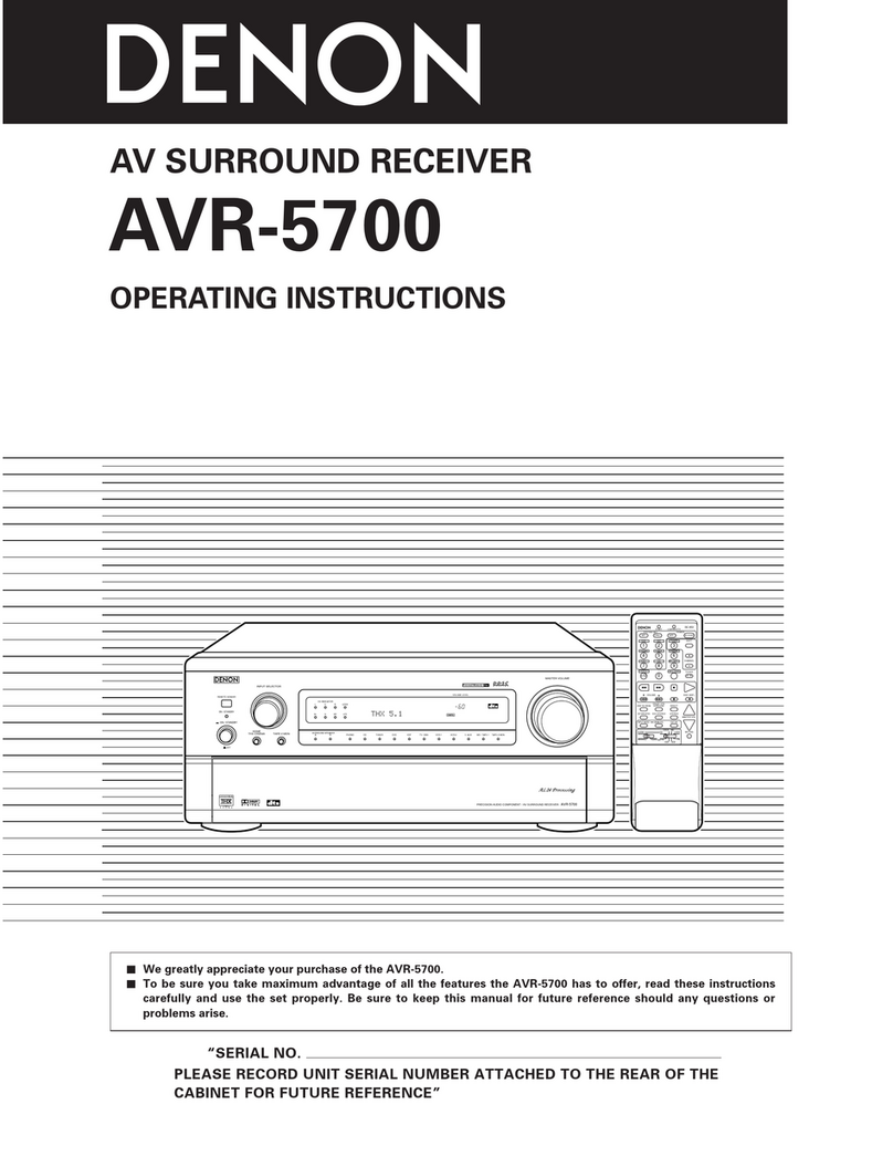
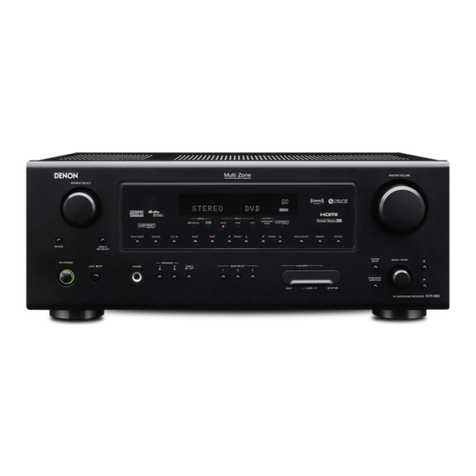
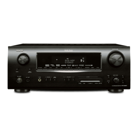
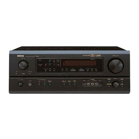
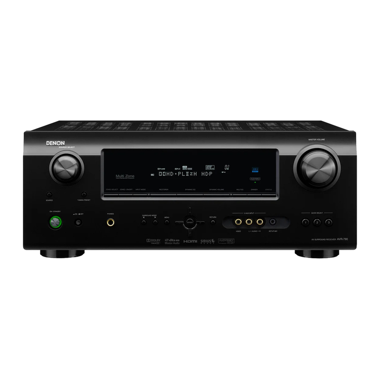
Denon DRA-565RD User manual

|
D
SEI
ON
10
N
Hi-Fi
AM-FM
Stereo
Reciever
MODEL
DRA-565RD
MODEL
DRA-
365RD
AM-FM
STEREO
RECIEVER
|
DRA-565RD
7
DRA-365RD
NIPPON
COLUMBIA
CO..LTD.
|

CAUTION
RISK
OF
ELECTRIC
SHOCK
DO
NOT
OPEN
CAUTION:
TO
REOUCE
THE
RISK
OF
ELECTRIC
SHOCK,
DO
NOT
REMOVE
COVER
(OR
BACK).
NO
USER
SERVICE-
ABLE
PARTS
INSIDE.
REFER
SERVICING
TO
QUALIFIED
SERVICE
PERSONNEL.
The
lightning
flash
with
arrowhead
symbol,
within
an
equilateral
triangle,
is
intended
to
alert
the
user
to
the
presence
of
uninsulated
“dangerous
voltage”
within
the
product’s
enclosure
that
may
be
of
sufficient
magnitude
to
constitute
a
risk
of
electric
shock
to
persons.
The
exclamation
point
within
an
equilateral
triangle
is
intended
to
alert
the
user
to
the
presence
of
important
operating
and
maintenance
(servicing)
instructions
in
the
literature
accompanying
the
appliance.
WARNING:
TO
REDUCE
THE
RISK
OF
FIRE
OR
ELECTRIC
SHOCK,
DO
NOT
EXPOSE
THIS
APPUANCE
TO
RAIN
OR
MOISTURE.
Rowformitétaerkiérung
Ore
=
DENON
Electronic
GmbH
Matskesirafie
32
40880
Ratingen
Ertan’
ats
Herstelter/imporieu:,
de8
Gas
in
dieser
Bedienungsanieitung
beschriebene
Gerat
den
Technischen
Yorschrifien
for
Ton
und
Ferneeh-Rundiunkemplinger
nach
der
Amisblaniverfigung
8068/1969
(Amisblan
des
Bundesminisiers
fur
Post
und
Telekhommunikation
vom
31.
8.
19891
entapricht.
PRECAUTIONS
FOR
INSTALLATION
Install
ORA-565/365R0
atweys
horizontally.
And
leave
at
least
10
cm
of
spece
between
this
unit
and
other
component
placed
above.
VORKEMRUNGEN
FOR
OIE
AUF
STELLUNG
Der
ORA-565/365AD
ist
stets
wasgerecht
eutrustelien.
AuGerdem
muB
ein
Mindestabstand
von
10
em
zwischen
diesem
Gerat
und
der
Komponents
gewahrieistet
werden,
die
derdber
gestellt
wird.
PRECAUTIONS
D'INSTALLATION
Le
ORA-565/365AD
doit
toujours
étre
installé
horizontalement.
Et
leisser
au
moins
un
espace
de
10
cm
entre
cet
epperei!
et
autre
compossm
plecé
su-dessus.
PRECAUZION
PER
L'INSTALLAZIONE
N
DRA-S65/365RD
viene
sempre
instaliato
in
modo
orizrontale.
Lesciste
uno
spazio
di
simeno
10
cm
tra
quest’unitd
@
un
eventuale
componente
sovrapposto.
PRECAUCIONES
PARA
LA
INSTALACION
instale
siempre
e!
DRA-565/365RD
en
posicién
horizontal.
Asegurese
también
de
dejar
un
espacio
de
por
lo
menos
10
cm
entre
esta
unided
y
ef
componente
que
ses
colocado
encima.
VOORZORGSMAATREGELEN
VOOR
INSTALLATIE
De
ORA-565/365RD
asitijd
horizontaal
plastsen.
En
minstens
10
cm
ruimie
laten
tussen
dit
toestel
en
het
andere
komponent
dat
u
erboven
pisatst.
FORBEREDELSER
FOR
INSTALLATION
Installer
sinid
ORA-565/365RD
horisontelk.
Limna
dtminstone
10
cm
melien
denna
apparat
och
en
annan
komponent
som
placeras
ovanpé,
PRECAUCOES
PARA
A
INSTALACAO
Iinstale
sempre
horizontaimente
o
DRA-565/365AD.
E
deixe
pelo
menos
10
cm
de
espero
entre
esta
unidade
e
o
outro
componente
colocedo
sacima.
10
erm
oF
greater
J
10
em
oder
mete
16
cm
ow
plus
10
em
co
pi
10
em
o
plu
10
em
of
meer
10
ern
efter
mer
10
em
ou
mois
ousoec/oaysegs’vyeo
me

NOTE
ON
USE/HINWEISE
ZUM
GEBRAUCH/
OBSERVATIONS
RELATIVES
A
L'UTILISATION
NOTE
SULL'USO/NOTAS
SOBRE
EL
USO/ALVORENS
TE
GEBRUIKEN/OBSERVERA
OBSERVACOES
QUANTO
AO
U
Avo
mgh
temper
etures
Altow
lor
sufficient
hest
dispersion
when
instatied
on
8
rack.
Vermeden
Sie
hohe
Tempersturen
Beachion
Sin,
de&
cine
susreicnend
tuf-
Uirtyleuon
gewéhrtersie
wird,
wenn
das
Tene
compte
d'une
dispersion
de
chaleur
sullaante
lors
de
linetatation
sur
une
Magére.
Evane
di
esporre
funnd
8
tempersture
ene.
Assur
stevi
che
cl
wa
un‘
sdeguats
disper.
voor
een
degetjk
hitteatvoer
indien
Opa
ae
ap
cen
ret
worm
geplsatet,
Se
nM
ef
det
fans
mofighet
ti
god
ornaaviedning
vid
momering
|
ett
rack.
Evite
ternperetures
sas
SO
Keep
the
set
tree
from
moisture,
weter,
and
Gust.
Hatten
Sle
dae
Gert
von
Feuchtighen,
Wasser
und
Steud
fern.
Protéger
Pepperell
contre
I'humidhé,
eeu
@t
te
poweslars,
Tenete
Punta
lortene
detf'umidité,
det’
se-
que
@
defle
potvere.
Mantengs
of
equipo
Nore
de
hwrneded,
aqua
y
polve.
Last
geen
vochtigheid,
weter
of
stof
in
het
epperset
"
Utean
ime
eppersen
fér
fukt.
vetten
och
damm,
Manterhe
o
eperetha
lwre
de
equsiquer
umidede,
bqus
ou
poeire.
"(For
sew
with
ventitetion
holes)
Oo
nat
obstsuct
the
ventilation
holes.
Ose
Seiutiungsdiinungen
adrten
nicht
ver:
decht
werden.
Ne
pet
obsiruer
ies
trous
d
edvation.
Non
coprhe
|
fori
di
ventilasione,
No
obetrvys
tos
orificion
Ge
venti#lacion.
De
vertiiatioopeningen
mogen
niet
werden
bettotkeerd.
Tapp
ime
un
vemilstionséppningama,
Nabe
ebsirve
o8
erificios
de
vemitecho.
Do
noi
tet
foreign
objects
in
the
set.
Keine
tremden
Gegenstinde
in
das
Gertt
E
importante
che
nessun
oggerto
¢
inserite
a
imerne
delTunka.
No
deje
ebdjetos
extradce
centro
del
equips.
Laat
geen
vreemde
voorwerpen
ia
dit
appersat
vation,
Se
tt
ott
himmande
irom
ime
ringer
in
i
epperaten.
Nae
Geine
odjetos
ettsenhos
no
apereino.
e
Do
not
tet
insecticides,
benzene.
and
thin-
ner
come
in
contact
with
the
set.
Lassen
Sie
des
Gert
nicht
mit
Insetuziden,
Bensin
oder
Verddnnungsmittetn
in
Be-
fehrung
bornmnen
Ne
pee
mettre
en
contect
des
insecticides,
Gu
benséne
et
un
diluent
evec
fepparsil,
Assicurstevvi
che
funkd
non
venga
in
contette
con
insenicidl,
benrole
a
sotventt.
Se
UM
att
inte
ineekternedel
92
spr
sybrur,
densen
ech
thinner
Lommer
i
tontatt
med
eppersions
hélie.
Nbe
permits
que
inseticides,
dentine
¢
Gescivente
entrem
em
contacto
com
0
eperetho.
Never
dtasssemble
or
modity
the
set
in
any
wey.
Versuchen
Sie
niemais
das
Cerit
susemnen-
Ger
te
nehmen
oder
sul
jegiche
An
ty
vee
Sadern.
Ne
jernsis
démonter
ou
modifies
Fepperet
Sune
menidre
ow
dune
evire
Non
wnoniate
msi,
ne
moditicaie
funta
in
ROtsun
moda.
Nunca
deserme
o
modifique
@!
equipo
de
ninguns
manera.
Moot
Of
soDsrast
demonteren
of
of
|
ondere
wise
Medifiéren.
Te
wee
iedt
oppersten
och
torsot
ime
Drege
om
den.
Nunca
éeemonte
ow
modifique
o
apereino
de
siguma
forma.
FRONT
PANEL
DRA.308RD
f2ss=
BY
a
|
lc
|
nee
|
fu
iy
It
1:
ts
\:
7
a
e
ORA-5O5RD
COON
fae
aaa
Bt
omar
ee
Ss
Cee
ae
Ree
pa
seal
(isasberdparei)
|||
~
anes
sono
(|
CLL
LL
LLL
|
ee
=a
i—)
eee
mee
eee
oe
f7a;>
0
@
sia
nbs
A
Lh
o
t
Le
SORBERRERELBE

Please
check
the
following
items
are
included
with
the
main
unit
in
the
carton:
{1)
Operating
instructions
.......
seecmnssssasonsnestsccnscecssesensesseces
(2)
AM
Loop
Antenna
on.
ccccccscccccccssecseseesees
sesebessbves
1
(3)
FM
AII@NNG
1...
cn
ecsssccsscssstsssecesscnsssssacsecersesecsoseessesee
|
(4)
Remote
Controt
RC-176
wooo
cssscesesecssesscscsscocorsmneese
1
(5)
Sateries
R6
(AA)...
stecesccemssccseesccensence
&
Bitte
dberprojen
Sie,
ob
die
folgenden
Telle
volistindig
In
der
Verpeckung
entheten
sind:
(VE
Bedienungsameitung
..........cccccsccscssscscesecessesesesereees
1
(2)
AM-Rahmenantenne
.............cc-.escc00
Siwdeecaas
sei
ssbavsecsess
1
13)
URW-AM@ANG
0.0...
cee
sessssesscsnecensssssssscerecesesessseseneess
1
(4)
Fernbedienungsgerdt
RC-174
occ
ceccereees
1
(5)
Trockenretie-Batterie
RE
(AA)
ooo.
ccccsceccocce.
budcoecds
2
Veuittex
controler
que
les
articles
suivents
sont
bien
joints
&
‘apparel
principal
dans
te
carton:
(1)
Mode
G'@rmplod
on...
eeeeeccessscccessncecsscscsrsossncecsnceceesesens
1
(2)
Amtenne-cadre
AM
oo...
cccccccnssccseseseseserseseressecsesnenece,
1
(3)
Antenne
FM
oon
cc
ccccsscsce
nocccsescsesecsecesccssemseseeses
.
1
(4)
Télécommande
RC-174
(5)
Plies
de
format
R6
(AA)
Controtiare
che
le
parti
seguenti
sl
trovine
imbeliste
con
Vapparecedio
nella
scatola
di
spedizilone.,
(1)
Istruzion!
per
l'uso
..
(2)
Antenna
AM
a
telsio
..
Sook
pets
tinassseas
cesses
woes
chesoseaSccacedeslecd
eae
(3)
Aten
FM
ounce
ccccsssssssesssscssassecevnsscessesssseseseseersess
1
(4)
Telecomando
RO-178
occ
cccccccscsesesecesee
ee
TS
|
(5)
Battoria
a
secco
RE
IAA)
ooo
cccccccccsceece
Por
favor
verifique
que
jos
siguientes
articulos
son
empacedos
en
ja
coje
pero
seperades
de
la
unidad
principal.
U1)
Instrucciones
de
operaciones
I
(2)
Amtoma
AM
de
Cuadr0
ounces
cccccccccsecscesessecseccocecseee
1
(3)
Antena
de
FM
oocscccucsc
se
iedte
ages
g
tan
A
(4)
Unidad
de
control
remoto
RC-1746
ooo.
ccccccccccccccce
(5)
Pitas
secas
RE
(AA)
ooo.
cccccccssccccsccescesccscoceecosseccescoecee
2
Kontroleer
of
de
voigende
accessoires
bij
het
hooldtoestel
in
de
dooe
ziin
verpekt:
(1)
Gebruthsaamw
izing
on.
ccccssccsesscssssssscecccccesese:
1
(2)
AM
-raamamtenne
.n....ccccccccsccscsstecsseccscsesssssestecessceces
1
(3)
FM-antenine
........cccccescsseseees
ba
gddcise
seavssieeaksoctetossockieestae:
i
(4)
Afstandsbediening
AC.
7
aiccotsiedessvvanssaisceisvasi
eaniee
1
(8)
RB
(AA)
droge
cel
batter]
...........
oibigvarseeccoscdtesacteceHuadacs
2
Kontrotiera
ett
fdljende
tilthehdr
her
packats
ner
|
kartongen
titsemmans
med
huvudenheten.
(1)
Bruksanvieni
es
a)
(2)
Ramantenn
(dr
AM.
nck.
2
oA
(3)
FMB
tennn
on...
scecesscssceceseecsessesseevarsestesssseceesccesenseececece
1
(4)
FiberkomtroN
RC-176
ccc
ctsactdaltca
eters
ccthe
1
(5)
RO(AAS
torrbation
ow.
ec
ccccsecsecscseccecscececcesscosesees
2
Certifique-se
de
que
as
seguintes
peces
estho
Inciuides
na
embetegerm
fora
de
unidade
principal:
(1)
bstrucdes
Be
Oper
abe
oon
ccccsccccecsessssccccesceseccseecese.
1
(2)
Arttens
de
Quadro
AM
oo....cccscccccsssccscecessccscssssecsssesees,
1
(3)
Antens
FM
.............
egueuseaiackees
eee
oboe
tas
acioscsditassesduiiys
sasests
1
{4}
Controle
remoto
RC-174
.
dada
cacshiesesttocaticeencastee
A
(8)
Pilhae
RE
(AA)
oy
VelbsegabsAbdodeseebacaeadacssesnssleccdbecesseeseieesicareeoe
For
multi-votsge
models
enty:
The
desired
voltage
may
be
set
with
the
VOLTAGE
SELECTOR
KNOB
on
the
rear
panel.
using
8
screwdriver.
Oo
not
twist
the
VOLTAGE
SELECTOR
KNOB
with
excessive
force
as
this
mey
cause
damage.
if
the
VOLTAGE
SELECTOR
KNOBS
does
not
turn
smoothly,
please
contact
@
quatified
servicemen.
(The
voliage
is
set
to
220
V
upon
shipment
trom
the
lactory.}
FREQUENCY
STEP
(Frequency
step
switeh!
Set
the
FREQUENCY
STEP
switch
es
described
below.
@
inthe
USA
and
Canade
-
set
the
switch
to
100
kHz
/
10
kHe
side
With
this
setting,
the
frequency
varies
in
100
kHz
sieps
in
the
renge
of
87.5
to
108.0
MHz
(FMI
end
in
10
tHe
steps
in
520
to
$790
kh
(AM),
Etsewhere
=
set the
switch
to
$0
kHz
/
9
kHz
side.
Wath
this
setting,
the
frequency
varies
in
50
kyr
steps
in
the
range
of
87.50
to
108.0
MHz
{FM}
and
in
9
hi
steps
in
622
to
1611
key
(AM),
Qysceec/OusSssc
voc
mam
DESIGNATIONS
AND
FUNCTIONS
OF
PANEL
CONTROLS
(Refer
to
Page
5.)
FRONT
PANEL
0
POWER
(Power
ON-STANOBY/OFF
Switch)
This
switch
turns
the
unit
ON
or
OFF.
There
is
a
delay
of
approximatety
3
seconds
before
the
unit
will
operste
after
this
power
switch
is
turned
ON.
If
the
unit
is
turned
OFF
from
the
remote
control,
the
unit
will
be
in
the
STANDBY
mode.
When
in
the
STANOBY
mode,
the
unit
can
be
turned
ON
with
the
power
button
on
the
remote
control.
If
the
unit
will
not
be
used
for
extended
period,
be
sure
to
turn
the
unit
OFF
from
the
front
panel
power
switch.
NOTE:
This
unk
includes
ea
STANOBY
protection
feature.
This
feature
is
designed
to
prevent
accidental
turn-on
from
the
STANDBY
mode
in
the
event
of
®
power
failure.
Should
AC
power
be
discon-
nected
and
then
reconnected
when
the
unit
is
in
STANDBY
mode,
the
unit
will
return
to
the
STANDBY
mode.
To
turn
the
unit
ON
from
the
STANOBY
mode
without
the
remote
control,
operate
the
front
panel
power
switch
four
times.
The
unit
will
then
operate
normally.
PHONES
(Heedphones
jack)
Connect
a
pair
of
headphones
(sold
separately)
to
this
jack
for
private
listening.
SPEAKERS
(Speaker
selector
switches)
These
switches
sre
used
fo
select
spesker
system
A
and
B.
No
sound
Is
heard
through
the
speakers
when
both
switches
are
reset
to
the
(
m
)
position.
REMOTE
SENSOR
(Remote
contro!
sensor)
This
sensor
receives
the
infra-red
light
transmitted
from
the
wireless
remote
control
unit.
For
remote
control,
point
the
wireless
remote
control
unit
towards
the
sensor,
BASS
(Bass
control)
Use
this
contro!
to
adjust
the
low-range
response.
When
the
control
is
set
to
the
center
position,
the
frequency
characteristic
curve
(below
1.000
Hz)
is
fiat.
Turn
the
control
clockwise
to
increase
the
bass
response
and
counter-
Clockwise
to
decrease
it.
TREBLE
(Treble
control)
Use
this
control
to
adjust
the
high-range
response.
When
the
control
is
set
to
the
center
position,
the
frequency
characteristic
curve
[above
1,000
Hz}
is
fiat.
Tuen
the
contro!
clockwise
to
increase
the
trable
response
and
counter:
clockwise
to
decrease
it.
BALANCE
(Balance
contro!)
Use
this
controt
to
balance
the
volume
levels
between
left
and
right
chenneis.
The
volume
levels
in
both
channels
are
equal
when
the
control
is
set
to
the
center
position.
VARIABLE
LOUONESS
(Loudness
control}
At
low
volumes,
the
human
ear
is
less
sensitive
to
low
(BASS)
and
high
(TREBLE)
frequencies.
Use
this
control
to
compensate
for
this
deficiency
when
listening
at
low
volume
levels.
Turn
this
contro!
counter-clockwise
until
a
natural
belance
of
bess
and
treble
sound
hes:
been
restored.
,
:
BASS
EQ
(DRA-565R0
only)
Press
this
button
to
switch
the
BASS
EO
ON
(=)
for
emphasis
of
bess
sounds.
Use
in
conjunction
with
the
bass
adjustment
of
the
tone
control
will
provide
further
emphasis
of
bass
sounds.
Set
this
switch
to
OFF
(
m
)
when
you
wish
to listen
with
a
normal
setting
condition.
VOLUME
(Volume
control)
This
knob
is
used
to
adjust
the
volume
level
of
both
channets.
Turn
the
knob
clockwise
to
raise
the
volume
and
counter-
clockwise
to
lower
it.
oO
input
selector
(Input
selector
buttons)
These
buttons
are
used
to
select
the
sudio
input
source.
oe
PHONO:
Press
to
play
a
record
on
a
record
player
connected
to
the
PHONO
input
jacks.
e
CO:
Press
to
listen
to
a
compact
disc
player
or
another
component
connected
to
the
CO
Input
jacks.
e
TUNER:
Press
to
fisten
to
FM
ar
AM
programs.
e
VIDEO:
Use
when
playing
back
the
audio
from
a
Hi-Fi
video,
video
disc
player
or
other
component
connected
to
the
VIDEO
terminal.
@
Tape
selector
(Tape
selector/monitor
buttons)
(DRA-S65RD)
TAPE:1;
Press
this
bution
once,
TAPE-1
indicator
will
light
up
and
then
you
can
pisy
tepe
source
on
TAPE-1
terminal.
in
this
state
you
can
copy
TAPE-1
source
to
TAPE-2
terminal.
TAPE-2:
Press
this
button
once,
TAPE-2
indicator
will
light
up
and
then
you
can
play
tape
or
video
source
of
TAPE-2
terminal.
Press
again
the
button
currently
accessed,
to
play
sources
selected
by
input
selector
é.
indicator
goes
out.
@
TAPE
(Tepe
monitor
button)
(ORA-365RD)
Press
this
button
once,
TAPE
Indicator
will
light
up
and
then
you
can
play
tape
source
on
the
TAPE
terminal.
Press
again
the
button
currently
accessed,
to
play
sources
selected
by
input
selector
@,
indicator
goes
out.
ROS
button
This
button
is
used
for
the
ROS
search
(refer
to
page
12)
and
PTY
search
(refer
to
page
12),
and
TP
search
(refer
to
pege
12)
operations,
and
to
input
the
station
name
(refer
to
pege
12,
13).
BAND
(Band
selector
switch)
Press
this
switch
to
select
the
FM
of
AM
(MY)
band.
AUTO
(Tuning
mode
button}
This
switches
between
auto
and
manual
tuning.
Auto
tuning:
When
the
UP
button
is
pressed,
the
radio
is
tuned
automatically
to
8
higher
frequency.
Press
the
DOWN
button
to
tune
to
@
lower
frequency.
Use
this
postion
to
eliminate
noise
when
no
signals
of
weak
signals
eee
being
received.
«
Manual
tuning:
In
this
position,
the
radio
can
be
tuned
manualty.
Reception
is
eutomaticaity
monaural
when
in
the
manual
mode.
TUNING
(Tuning
buttons)
Use
these
to
chenge
the
received
frequency
to
a
higher
frequency
(UPi
of
a
lower
frequency
(DOWN).
When
writing
station
names.
use
these
buttons
to
select
the
letters.
(Refer
to
Page
13.)
MEMORY
(Memory
button)
This
ewitch
is
used
to
store
the
desired
radio
station
to
»
memory.
©
Presetting
stations
After
pressing
the
MEMORY
button,
press
the
SHIFY/
PTY
button
to
select
the
memory
block,
A
to
E.
Now
use
the
PRESET
UP
and
DOWN
buttons
to
specify
the
preset
channel
number.
Press
the
MEMORY
button
agsin
to
store
the
station
at
the
specified
preset
channel.
Prasat
(Preset
station
buttons)
These
duttons
are
used
for
storing
stations
or
recalling
stations
which
have
been
preset.
Using
the
SHIFT
button
you
can
preset
a
total
of
40
FM
of
AM
stations
into
preset
channels.
Once
8
radio
has
been
memorized,
the
seme
station
can
later
be
tuned
in
instantly
simply
by
recalling
the
corres-
ponding
preset
channel
with
PRESET
UP
or
DOWN
button.
DISPLAY
8
86
8
88s
6
ROS
Indicator
This
lights
when
recaiving
ROS
broadcasts,
and
Hashes
during
the
ROS
saarch
operations.
TA
Indicator
This
fights
when
receiving
traffic
announcements.
TP
indtcator
This
fleshes
during
the
TP
search
operation
and
fights
when
TP
stations
are
tuned
in.
PTY
indicator
This
flashes
during
the
PTY
(Programme
type)
search
operation.
TUNED
indicator
This
tights
when
a
station
is
properly
tuned
in.
STEREO
indicator
This
lights
when
receiving
stereo
broadcasts.
It
remains
off
when
receiving
AM
broadcasts.
AUTO
indicator
This
indicates
the
tuning
mode.
It
lights
in
the
auto
mode,
and
remains
off
in
the
manual
mode.
NOTE:
©
TP
(Traffic
Programme)
Stations
scheduled
to
brosdcast
traffic
programmes
e
TA
(Traffic
Announcement)
Traffic
information
broadcasts
REAR
PANEL
(2)
FM
ANT
(FM
antenna
terminals)
75-ohm
coaxial
cable
can
be
connected
to
this
terminal.
For
antenna
connecting
procedure,
see
the
ANTENNA
IN-
STALLATION.
GND
(Grounding
terminal)
The
grounding
wire
of
the
turntable
is
connected
here.
«
Hum
or
noise
may
be
generated
H
the
grounding
wire
is
Not
connected.
AM
ANT
(AM
antenna
terminals}
Connect
the
attached
AM
loop
antenna.
(Refer
to
page
10
for
connections).
Connect
to
this
terminal
when
e@
medium
wave
outdoor
antenna
is
used.
PHONO
(Phono
Input
terminats)
The
output
cord
of
the
turntable
ts
connected
here.
Since
the
input
sensitivity
of
“PHONO”
is
extremety
high,
do
not
use
the
unk
without
the
input
pin
cord.
If
used
without
this
cord,
the
speakers
mey
generate
hum.
co
The
output
cord
of
the
CO
player
is
connected
here.
VIDEO
A
VIDEO,
such
as
a
VCR
or
Video
Dise
may
be
connected
here.
©
TAPE-1,
TAPE-2
(Tape
deck
playback
/
recording
terminal}
(DRA-565RD)
Two
tape
decks
of
tape
deck
can
be
connected
to
these
jacks
for
full-fledged
playback.
recording
and
tape
dubbing
operation.
@
TAPE
(ORA-36SRD)
Tape
decks
can
be
connected
for
full
use
including
playing
or
copying.
®
Se
@
e
SHIFT/PTY
button
Use
this
button
to
select
the
memory
blocks,
A
(110
8),
B
(1
to
8,
C
(1
to
8),
O
(1
to
8)
or
E
(1
to
8).
For
PTY
search.
use
this
bution
to
select'the
program
type.
When
writing
station
names,
use
this
bution
to
set
the
writing
position.
MEMO
indicator
This
indicator
lights
for
approximately
10
seconds
when
the
MEMORY
button
has
been
pressed
and
8
station
can
be
stored
on
a
PRESET
CHANNEL
button.
This
flashes
continuously
during
the
auto
memory
opera.
tion.
CH
indicator
This
lights
when
the
preset
channel
number
and
shih
mode
(A,
8,
C,
0
of
E)
are
displayed.
©
TAPE-1/TAPE-2
indicator
(DRA-565R0)
The
TAPE-!
indicator
lights
when
the
TAPE-1
source
is
selected
with
the
tape
selector
buttons.
The
TAPE.2
indicator
lights
when
the
TAPE-2
source
is
selected.
e@
TAPE
Indicator
(DRA-365RD)
The
TAPE
indicator
lights
when
the
TAPE
source
is
selected
with
the
tape
selector
buttons.
Muti
function
display
This
displays
the
frequency,
station
name,
programme
type,
etc.
PRE-OUT
(DRA-565RD
only)
Output
signais
for
power
amplifiers
are
sent
trom
these
jacks.
The
rated
output
is
2
volts.
SPEAKER
SYSTEMS
(Speaker
terminals)
Two
pairs
of
speakers
A
and
B
can
be
connected
to
these
terminals.
AC
OUTLET
(AC
power
outlets)
This
AC
outlet
is
controlled
by
the
power
switch
and
Remoto
controtunit
(DRA-S65AD),
controlied
by
the
power
switch
[ORA-365R0).
AC
CORO
(Power
cord)
Connect
this
cord
into
the
wall
outtet.
BQOHSSe/aHsss-vywa
AE
aA
RI
I
Ie
EN
Ta
SUS
SE
ED
a
re
ra
ee
EEO

10
NOTES
SPEAKER
CONNECTION
@
This
receiver
has
a
full
back-up
system.
When
the
power
is
turned
Svoid
this,
keep
ihe
receiver
as
far
away
from
other
video
Confirm
potarity
(+,
-)
and
left
end
right
channels
{L,
RA).
Connect
the
on,
the
INPUT
SELECTOR
buttons
are
set
to
the
lest
mode
set
components
as
possible,
or
plece
the
AM
loop
antenna
where
spesker
pairs
to
the
SPEAKER
terminals
A
or
nen
the
vse
panel.
before
the
power
was
turned
off.
noise
ls
reduced.
if
the
noise
is
not
reduced,
turn
off
the
power
of
Connections
must
be
made
with
power
cord
disconnected.
e
When
using
this
receiver
in
close
proxmity
to
video
equipment
the
video
components
when
listening
to
AM
brosdcasts.
(TV,
VCR,
VOP,
etc.),
nose
may
be
generated
in
AM
broadcasts.
To
CONNECTIONS
vcr
DIRECTION
OF
.
ee
ie
beens
AM
loop
antenna
BROADCASTING
STATION
[Video
Ceasette
Recorder)
aoe ae]
ae
|
ce
2
sais
[er]
(AS
el
O
OUS9L/OUuSSS-VyO
mm
2.
Twist
the
wires.
Speaker
(A)
SPEAKER
(8)
1.
Loosen
by
turning
counterciockwise.
e
o
2.
Insert
the
cord
and
tighten
by
turning
clockwise.
o-
8
Notes
on
Connection
CAUTION
———)
5
e
Oo
not
the
power
cord
into
the
AC
wall
outlet
until
aft
Protective
Cirauht
SP,
CF,
alate
°8
nat
Say
——
=
connectors
have
been
completed.
This
set
is
equipped
with
a
high
speed
protective
circuit,
=,
TAPE
DECK
1
:
¢
Make
sure
channets
are
correctly
connected.
Connect
Left
This
circuit
protects
the
internal
circuitry
trom
damage
due
Ss
channets
to
Left
channels
and
Right
channels
to
Right
to
large
currents
flowing
when
the
speaker
jacks
are
not’
TURNT
tase
Pisieapad
ied
igen
la
Ses
recrenervats
completely
connected
or
when
an
output
is
generated
by
a
a
Connect
all
pin-piugs
securety,
pushing
them
completly
into
SHOR
circuit,
the
jacks.
incomplete
connections
will
cause
nolse
genera-
This
protective
circuit's
operation
cuts
off
the
output
to
the
ANTENNA
INSTALLATION
thon.
speakers.
in
such
a
case,
be
sure
to
turn
the
power
to
the
e
FM
ANTENNA
Binding
the
connection
cables
to
power
cords,
or
running
such
cables
close
to
power
supply
transformers
will
cause
humming
or
noise,
and
should
thus
be
svoided.
set
off
and
check
the
connections
to
the
speakers.
Then
turn
the
power
on
again.
After
muting
for
several
seconds,
the
set
will
operate
normally.
The
supplied
indoor
FM
antenna
can
be
used
inside
wooden
houses
for
receiving
local
FM
stations
and
other
strong
FM
signals.
Stretch
out
the
ends
of
the
antenna
end
mount
the
antenns
on
the
wall
of
calling
where
optimum
reception
is
achieved.
A
indoor
FM
antennas
may
not
consistently
ensure
stable
reception,
due
to
environment
changes.
In
such
cases,
the
indoor
FM
antenna
should
only
be
used
temporarity
until
an
outdoor
FM
antenna
has
been
installed.
When
connecting
an
outdoor
FM
antenna,
the
use
of
75
ohm
coaxial
cable
(3C-2V,
5C-2V)
is
stronpty
recommended.
Notes:
e
Oo
not
connect
two
FM
antennas
sirnuttaneousty.
©
Even
Hf
an
external
AM
antenna
is
used,
do
not
disconnect
the
AM
tfoop
antenna.
e
Make
sure
AM
loop
antenna
lead
terminals
do
not
touch
metal
paris
of
the
panel,
e
AM
ANTENNA
Attach
the
supplied
AM
loop
antenne
even
when
uting
an
outdoor
AM
antenna.
Connect
the
leeds
to
the
AM
and
GNO
terminals.
g
Also
use
the
AM
termingis
for
connecting
an
outdoor
AM
antenna
lwhen
meking
such
@
connection
do
not
disconnect
the
AM
loop
antenna.)
Adjust
the
loop
antenna
to
obtain
optimum
reception.
Where
broedcast
stations
are
distant
and
onty
weak
signals
are
recetved,
or
where
signals
are
blocked,
it
is
best
to
install
an
outdoor
AM
©
Remove
the
ie
lestening
the
loop
entenne's
bead
antenna,
ond
connect
ihe
teed
to
the
amenns
torminats.
ae

Using
the
Various
Functions
1.
12
Presetting
stations
in
the
memory
The
frequency
and
the
name
of
the
radio
station
fincluding
names
which
you
have
input
yourself),
are
also
stored
in
the
memory.
In
particular,
the
various
ROS
functions
can
be
used
affectivety
when
ROS
stations
are
stored
in
the
memory.
How
to
preset
the
memory
Press
the
MEMORY
button
@.
The
“MEMO”
indicator
on
the
display
@
tights.
Next,
use
SHIFT/PTY
button
@
to
select
the
memory
block
A,
B,
C,
D
or
E.
Now
press
the
PRESET
UP
or
DOWN
button
©
to
specify
the
preset
channel
number,
and
then
press
the
MEMORY
buiton
@
to
store
the
stetion
in
the
memory.
The
preset
channel
numbers
for
the
different
memory
biocks
are
as
follows.
Memory
block
A
:
10
8
Memory
block
8
:1to
8
Memory
block
C
:1to0
8
Memory
block
DO
:1to
B
Memory
bieck
E
:
lto
8B
.
Auto
Memory
(FM
onty)
The
ORA-565R0/ORA-365AD
Is
equipped
with
an
auto
mem-
ory
function.
:
Connect
the
antenna,
set
it
so
that
stations
can
be
received,
(hen
hold
in
the
MEMORY
button
and
press
the
POWER
button
ta
turn
the
power
on.
Stations
for
which
the
auto
stop
function
operates
are
stored
in
the
preset
memory
in
the
order
Al
to
A8.
8!
to
B8,
and
so
on,
through
E8.
Channet
Al
is
tuned
in
after
the
auto
memory
operation
is
comoleted.
Using
this
function
makes
it
possible
to
find
out
the
overall
reception
conditions
of
the
receivable
stations.
The
memory
can
be
used
effectively
by
recalling
the
channels
in
the
preset
memory
and
replacing
stations
whose
reception
is
poor
with
stations
whose
reception
is
good,
using
the
procedure
de-
scribed
in
1
above.
.
Recaiiing
preset
stations
Use
the
SHIFT
/PTY
button
©
to
select
memory
block
A.
B,C,
D
of
E,
then
press
the
PRESET
UP
or
DOWN
button
@
to
recall
the
station
stored
in
the
memory.
tf
the
PRESET
UP
or
DOWN
buttons
are
pressed
without
pressing
the
SHIFT/PTY
button
@,
the
stations
are
recalied
in
the
order
Al
to
AS,
81
to
BS,
and
so
on,
through
£8.
-
ROS
search
(for
FM
onty)
Use
this
function
to
automatically
tune
to
stations
offering
Radio
Date
Service.
This
operation
is
also
possible
by
pressing
the
TUNER
button
on
the
remote
contrat
unit
once
when
the
function
is
set
to
the
TUNER
mode.
Operation
;
Display
1.
Prees
the
ROS
bution
@
once.
ROS
SEARCH
2.
Press
the
PRESET
UP
or
|
COWN
bution
@.
"ROS
SEARCH"
flashes
on
the
Oepley.
(Preset
memory
chennets
A!
to
€8
ore
being
searched.)
Hf
no
ROS
station
le
found
with
the
sdove
eperastion,
at
the
reception
bends
ere
searched.
The
stetion
neme
is
displeyed
afler
seerching
stops.
3.
Press
the
PRESET
UP
or
ROS
search
starts
again.
OOWN
button
egesin
while
the
ROS
mart
is
flashing.
{it
no
other
ROS
Station
is
found
when
aif
the
frequencies
are
searched,
“NO
ROS°
is
Gisplayed.)
.
PTY
search
(for
FM
onty)
Use
this
function
to
find
stations
broadcasting
a
designated
type
of
programme
type
(PTY).
This
operation
is
siso
possible
by
pressing
the
TUNER
button
on
the
remote
control
unit
twice
when
the
function
is
set
io
the
TUNER
mode.
Next,
press
the
PANEL
button
on
the
remote
control
unit,
select
the
PTY,
then
press
the
PRESET
UP
or
OOWN
buttons
to
start
the
PTY
search
lunciion
in
the
specified
direction,
Operation
Oisplay
1.
Press
the
ROS
Dutton
twice.
PTY
SEARCH
i
Prograsyme
type
of
PTY
2.
Press
the
SHIFT/PTY
bution.
Designated
programme
type
[Abways
do
this
to
designate
the
programme
type
Hd
“PTY”
is
displayed
im
step
1.)
3.
Press
the
PRESET
UP
o¢
“PTY
SEARCH”
flashes
on
the
DOWN
bution
@.
Gisplay.
{Preset
memory
channels
Al
to
E8
sre
being
searched.)
®
there
ss
no
station
brosd
casting
Be
designated
programme
type
with
the
sbove
operation,
all
the
recegtion
bends
are
searched.
The
atten.
asme
is
displeyed
eher
searching
stops.
4.
Press
the
PRESET
UP
or
PTY
semrh
starts
again.
OOWN
button
again
while
the
PTY
mart
is
flashing.
(
no
other
station
brosdcasiing
Ihe
cesigneted
programme
type
is
found
when
afi
the
frequencies
ere
searched,
“NO
PROGRAMME?
is
Giepleyed.)'
*
The
programme
types
which
can
be
depisyed
are
listed
on
Page
13.
6.
TP
Search
(for
FM
onty)
This
function
is
used
to
find
stations
scheduled
to
broadcast
traffic
programmes
(TP
stations).
This
operation
is
stso
possible
by
pressing
the
TUNER
button
on
the
remote
control
unit
three
times
when
the
function
is
set
to
the
TUNER
mode.
Operation
Dvepiey
1.
Press
the
ROS
button
@
TP
SEARCH
2
thmes.
i
2.
Press
the
PRESET
UP
or
“TP
SEARCH”
flashes
on
OOWN
bution
@.
the
display.
Preset
memory
channels
Ai
to
£8
are
Being
searched.)
4"
no
TP
mation
is
found
with
the
abeve
operation,
all
the
recagtion
bands
are
seeorchea,
The
station
name
is
displeyed
atier
searching
stops.
3.
Press
the
PRESET
UP
or
TP?
search
starts
again.
dution
again
while
the
TP
mark
is
hing.
(4
ne
other
TP
station
is
found
when
eff
the
frequencies
are
searched,
“NO
PROGRAMME”
is
diepievyed.)
7.
Writing
stetion
nemes
You
can
write
in
station
names
yoursett.
(Up
to
8
characters)
(Reter
to
the
table
of
characters
on
pege
11}
Oper
stion
Sispley
1.
Press
the
ROS
button
First
chasecter
Rashes.
2.
Use
the
TUNING
eng
flemt
lemer
Reenes.
Ros
Aderm
“ALARM®
will
flesh
on
the
displey
when
the
unit
receives
the
Emergency
Programme
Type
Code
(PTY31}
from
an
ROS
steson.
This
feeture
mey
not
operste
property
Hf
the
signe!
fern
the ROS
station
is
too
weet
or
te
subjected
to
interference.
his
not
possible
to
select
the
“ALARM™
diaplay
from
the
PTY
search
mode.
&.
Claaring
station
names
1.
2.
Recall
the
station
name
you
want
to
clear.
Press
the
RDS
button
4
times
until
the
character
at
the
first
piace
flashes.
.
Then
press
the
SHIFT/PTY
button
for
at
least
2
seconds.
The
current
station
name
will
then
be
cleared.
:
Station
names
must
be
stored
in
a
preset
memory
to
be
retained.
If
the
power
Is
turned
off,
or
if
the
band
(AM/FM)
is
changed,
the
station
name
will
be
fost.
Be
sure
to
store
ihe
entered
station
name
in
a
Preset
Memory
before
changing
the
band
or
turning
the
power
switch
OFF.
The
following
programme
types
can
be
designated:
[NEWS
sd
EWS
NEWS
(HEFATRS———]
sane
vente
trom
covenon
om
curun
row
veo
rr
muse
nok
muse
Tabie
of
characters
The
characters
are
input
in
the
order
shown
to
the
right.
Use
the
TUNING
buttons
@
to
select
the
desired
characters.
RBC
DEFGHIGKLMNOPGR
Surry
O'C3S4YSEIBIC
3-8
sss
et.
-.
M.0.R.
MUSIC
UGHT
CLASSICS
SERIOUS
CLASSICS
OTHER
MUSIC
13

14
¢
PLAYBACK
USING
THE
REMOTE
CONTROL
Besides
being
able
to
operate
the
DRA-565RD/365RD
receiver
with
this
remote
control
unit,
you
can
also
;
operate
a
DENON
cassette
deck
and
CD
player
from
this
handy
full-system
remote
control
unit.
The
accessory
AC-174
remote
contro!
unit
is
used
to
contro!
the
RECEIVER
from
a
distance.
Remote
Control Section
(1)
inserting
the
dry
ceff
batteries
Notes
on
Use
of
the
Batteries
Full-system
Remote
Control!
Unit
1
Remove
the
reer
cover
on
the
remote
contro!
unit.
©
The
remote
control
unit
uses
size
“AA”
(R6!}
dry
cell
batteries.
The
full-system
remote
control
unit
operates
all
major
functions
of
the
receiver
such
os
function
switching,
volume
control,
and
preset
e@
The
batteries
will
need
to
be
replaced
approximately
once
a
stetion
selection.
But
thet's
not
alll
The
same
contro!
pad
can
also
control
the
major
functions
of
a
DENON
CO
player
and
cassetie
deck
to
year,
This
will
depend
upon
how
often
the
remote
control
is
create
a
remarkably
ergonomic
and
versatile
OENON
system
with
all
the
quality
sound
seproduction
that
the
devoted
audiophile
expects.
used,
.
SS
@
If,
in
tess
than
8
year
from
the
time
new
batteries
were
Remote
Control!
Unit
RC-174
supplied
with
DRA-565RD/365RD
<>
inserted,
the
remote
control
fails
to
operate
the
receiver
trom
a
Sf:
near-by
postion,
it
is
time
to
replace
the
batteries.
|
DECK
J
©
Insert
the
betterles
property,
following
the
diagram
on
the
OHuSSrvouses-vHo
mm
remote
control
battery
supply
unit,
and
making
sure
to
atign
the
plus
and
minus
sides
of
each
battery.
2
Insert
two
size
“AA™
(RE)
dry
cell
batteries
as
shown
in
bf
oo
Lacie
pathagilie
a
a
ed
be
ese:
PLAY
{REVI
button
POWER
bution
;
°
not
com
n
ries
with
u
,
DUE
ARO
STEAD
OO
ADE,
RUE
MU
PONY
UN:
e
Do
not
combine
different
types
of
batteries.
©
Do
not
jumper
the
opposite
poles
of
the
batteries,
expose
them
to
heat
or
break
them
open,
or
put
them
into
open
[cb]
=
fire.
Refer
to
the
1S
e
When
the
remote
control
is
not
to
be
used
for
a
tong
period
of
Operating
mst:
A
tlme,
remove
the
batteries
from
the
unit.
ructions
of
your
PLAY
bution
@
If
the
batteries
have
feated,
remove
any
battery
fluid
from
the
OENON
tape
inside
of
the
battery
supply
unit
by
wiping
it
oul
thoroughly,
’
deck
STOP
button
Al
Cc
Reverse
Track
and
insert
new
batteries.
AIB
W-DECK
rat
Ris
Sa
Ned
Search
button
3
Replace
the
rear
cover.
PANEL
bution
we
Forwerd
Track
Search
bution
PAUSE
bution
REPEAT
button
RAMDOM
bution
names,
programme
types
and
the
time
OSc
SKIP OfSC
SKIP
bution
This
ta
only
possble
on
tne
DRA-S&5AD.
,
a
,
are
only
displayed
when
recewing
ROS
7
stations.
b4
:
RLQY
”
poem
BC
ve
FUNCTION
SELECTOR
buttons
CoOCICo
The
tollowing
may
sppee:
on
the
Giepisy
for
The
display
switches
between
the
fre:
quency,
manuat
characters,
station
,
name,
programme
type
end
time
sech
time
tNis
Dutton
is
pressed.
Station
{2)
Directions
for
use
some
stations,
but
this
is
not
a
malfunction:
©
Operate
the
remote
contro!
unit
while
pointing
it
towards
the
NO
PTY":
This
is
en
ROS
broadcast,
but
the
remote
contro!
sensor
on
the
receiver
as
shown
in
the
diagram
Progrem
type
[PTY]
is
not
being
left.
broadcast.
“NO
PS*:
An
ROS
broadcast
is
being
re
ceived,
but
the
PS
(Programme
Service
name
or
station
nsme)
is
©
The
remote
control
unit
can
be
used
st
distances
up
to
sbout
8
meters
in
8
straight
line
from
the
receiver.
This
distance
will
VOLUME
buntons
(4
¥}
Gecreate
if
there
are
obstructions
blocking
the
infra-red
fight
NOt
being
received
due
to
week
transmission
or
Hf
the
remote
contro!
unit
is
not
directed
signals,
ete.
straight
at
the
receiver.
“NO
TIME
DATA":
This
is
displeyed
when
the
station
currentty
tuned
in
ia
not
broadcast-
PRESET
dDuttons
{A
¥V)
ing
time
dsta,
and
mey
be
diplayed
for
one
mi-
fnwte
after
the
power
is
turned
on
even
when
the
station
currently
tuned
in
ts
§=
broadcasting
time
m
dale.
Note
on
Operation
(The
PANEL
bution
onty
opersies
when
the
©
Oo
not
press
the
operating
buttons
on
the
receiver
and
the
remote
contro!
unit
at
the
same
time.
This
will
cause
misoperation.
function
ts
set
io
the
TUNER
mode.)
©
Operation
of
the
remote
contro!
unit
will
become
less
effective
or
erratic
Hf
the
Infrared
remote
control
sensor
on
the
receiver
is
exposed
to
strong
light
or
if
there
are
obstructions
between
the
remote
controt
unit
and
the
sensor.
¢
!n
case
you
operate
your
VCR,
TV
or
othar
components
by
remote
control,
do
not
operste
buttons
on
two
different
remote
control
units
at
the
same
time.
This
will
cause
mis-operstion.
Operate
the
monitor
of
the
DRA.I6SRO
tope
deck
with
the
TAPE
MONITOR
button.
@
The
RC-174
Remote
Control
Unit
can
controt
CO
players
and
cassette
decks
made
by
DENON.
Note
that
operation
may
not
be
possible
for
some
models.
©
Buttons
are
conveniently
separated
into
groups,
each
group
controlling
one
specific
component,
The
groups
are
RECEIVER,
CO
ana
DECK.
For
details
on
operating
other
componenis,
reter
to
the
instruction
manuals
for
the
CD
player
and/or
cassette
deck.
CAUTION:
@
If
the
power
is
turned
off
with
the
remote
control
unit,
the
receiver
is
switched
to
the
power
stand-by
stale.
if
you
sre
to
be
absent
fore
jong
period
of
time,
be
sure
to
turn
the
power
off
using
the
POWER
switch
on
the
receiver.
©
A
part
of
Ist
digit
of
fluorescent
display
light
while
the
receiver
is
in
the
Power
stand-by
state.
©
You
may
experience
erratic
operation
of
the
remote
control
unit
if
it
is
operated
in
fluorescent
light
and
direct
sunlight,
in
pacicular
if
this
light
strikes
the
remote
contro!
sensor
on
the
receiver,
However,
this
is
not
a
maifunction,
and
if
this
should
happen,
protect
the
sensor
against
such
light.
15

TROUBLESHOOTING
1.
Have
all
conrections
been
made
PROPEALY?
2.
Have
you
followed
all
operationat
instructions
correctty?
3.
Check
speake:
and
the
turntable
systerns
for
Proper
operation.
When
your
unit
does
not
seem
to
be
operating
correctly,
first
check
the
items
in
the
following
table.
if
the
symptom
does
not
correspond
to
any
of
(he
problems
as
shown
below,
turn
of
the
power
sources
Immediately
and
contact
your
DENON
dealer.
Check
the
connection.
Check
the
antenna
instslistion.
Radio
program
can
not
be
received.
©
Antenna
connection
is
wrong.
©
A
signal
strength
Is
weak.
Install
an
outdoor
antenna.
e
Keep
the
antenns
away
from
the
street.
©
Keep
the
equipment
away
from
this
set,
or
turn
off
the
power
of
the
other
equipment.
Noise
is
reproduced.
A
signal
strength
is
weak.
Automobile
ignition
noise
interferes
with
reception.
e
Other
etectrical
equipment
interteres
with
reception.
The
preset
frequencies
are
erased.
The
memory
back-up
term
(about
|
month)
pessed.
in
automatic
tuning,
the
frequency
doesn't
stop
at
the
radio
station.
A
signal
strength
is
weak.
Use
manual
tuning
In
automatic
tuning,
it
stops
at
the
one
step
lower
or
higher
frequency
then
the
radio
station.
Use
manual
tuning
for
optimum
re-
Noise
of
strong
signal
strength
is
‘
ception.
received.
No
sound
is
produced
with
power
on.
Input
and
speaker
cords
connection
Check
the
connection.
ere
wrong.
©
Speaker
switch
Is
off.
e
The
INPUT
SELECTOR
buttons
sre
in
wrong
position.
The
protective
circuit
is
operating.
Turn
on
speaker
switch.
e
Check
these
position.
©
Turn
the
power
off
once.
check
the
connections
to
the
speakers,
then
turn
the
power
on
again.
@
Ask
your
dealer,
of
the
nearest
OENON
representative.
The
fuse
has
biown
out.
Audible
hum
when
playing
records.
The
input
and
grounding
cords
con-
Check
the
connection.
nection
of
the
turntable
are
wrong.
¢
The
cords
connection
of
the
cartridge
are
wrong.
e
The
interference
from
the
nearby
TV
or
radio
transmission
antenna,
Check
the
connection.
@
Ask
your
dealer,
of
the
nearasi
DENON
respresentative.
The
vibrations
snd
sounds
transmit
from
the
speakers
to
the
turntable.
Howling
is
produced
when
the
volume
control
is
turned
up
too
high
while
play-
ing
records.
Insulate
the
vibrations,
of
heap
the
speakers
away
from
the
turntable.
Cracking
noise
is
produced
when
playing
records.
The
record
is
stained
with
the
dust.
Clean
the
record.
o
The
stylus
tip
of
the
cartridge
is
stained
with
the
dust.
The
cartridge
is
defective.
Clean
the
stylus
tip.
Try
the
other
cartridge.
16
SPECIFICATIONS
AMPUFIER
SECTION
Continuous
Power
Output:
(DON)
Power
Bandwidth
(IHF):
Total
Harmonie
Distortion:
Frequency
Response:
input
Sensitivity
and
impedance:
Mazimurn
input
Level
(at
1
kha):
Signal
te
Noise
Ratio
(HF
-A);
Tene
Contre:
Loudness,
Contre!
Effect:
PRE-OUT
terminals
Rated
output:
(ORA-666RD
onty)
ORA-SOBRD:
80
W
+
80
W
(4d
ohms,
I
bz)
ORA-305RD:
62
W
+
62
W
(4
ohms,
1
kHz}
10
Hz
~
40
kHz
(7.4.0.
0.16%
both
channets
driven
into
8
ohms)
0.03%
(-3
68
at
rated
output,
8
ohms)
PHONO
RIAA
Standard
Curve
(Record-
ing
Output)
MM
20
He
~
20kMz
20.808
CO,
VIDEO,
20
Hz
~
SO
kHe
£1.85
c8
(at
1W)
TAPE-1,
TAPE-2
(ORA-5S85RD)
TAPE
(ORA.
365A0)
PHONO
MM
25mV
4)
kh
ohms
CO.
VIDEO,
18O0mV
=
Mkohma
TAPE-1,
TAPE-2
(DRA-SO5A0)
TAPE
(DRA.
366R0)
PHONO
MM
120
mv
PHONO
MM
76
68
(at
5.0
mV
Input)
CO,
VIDEO,
96
@8
TAPE.1,
TAPE-2
(DRA-BESRO)
TAPE
(ORA-IOBRD}
Bass
£10
6B
at
100
Hz
TREBLE
210
68
at
10
kids
VARIABLE
LOVONESS
at
maximum
position
$Q
H2/10
kHz,
+10
6B/
+8
68
2
V
(at
100
kohm
load)
TUNER
SECTION
[FM]
(note:
UV
at
7$
ohms,
O08!
-
1%
10
'
Ww)
Recetying
Range:
Usable
Sensitivity:
Signal
to
Noise
Aetic
(IHF-A):
image
Rejection:
Setectivity
(1300
kHz):
Frequency
Response:
Stereo
Separation
lat
1
kPtz):
1AM]
Receiving
Range:
Usedle
Sensitivity:
Signal
to
Noise
Ratio:
Generel
Power
Supply:
Power
Consumption:
Power
Outlets:
Otenensions:
Weight:
REMOTE
CONTROL
UNIT
Remote
control
system:
Power
supply:
External
dimensions:
Weight:
87.5
~
108
MHz
0.9uV
(10.3
Bf)
MONO
8248
STEREO
7846
6508
$548
JOM:
~
15kes
*
02
1
a8
5
40
af
$22
~
1681
AM
1ByV
$5 08
AC
230V
$0
Ha
145
W
(ORA-585RD)
120
W
(ORA-365A0)
SWITCHED
100
W
434
men (W)
«
130
mm
(H)
«
12
mm
(0)
(ORA-565R0)
434
mm
(W)
«
120
mm
(H)
=
312
mm
(0)
(ORA-3E8RD)
7.2
tg
(ORA-565A0)
6.0
kg
(ORA-365R0)
RC-174
infrared
pulse
system
IV
OC
Two
size
“AA™
(RG!
Gry
cell
bettertes
60
mm
W
x
175.
mm
2
18mmO
120
g
iInctudes
batieries)}
Design
and
specifications
are
subject
to
change
without
prior
notice.
17
Other manuals for DRA-565RD
2
This manual suits for next models
1
Table of contents
Other Denon Stereo Receiver manuals

Denon
Denon AVR-1912 User manual

Denon
Denon AVR-786 User manual

Denon
Denon AVR-S500BT User manual

Denon
Denon AVR-791 User guide

Denon
Denon AVR-1609 User manual

Denon
Denon AVR-X3400H User manual

Denon
Denon AVR-S640H User manual

Denon
Denon AVR-990 User manual

Denon
Denon AVR-1907 User manual

Denon
Denon DN-700AVP User manual

Denon
Denon DRA-685 User manual

Denon
Denon DRA-385RD User manual

Denon
Denon AVR-1911 User guide

Denon
Denon AVR-S540BT User manual

Denon
Denon AVR-X4100W User manual

Denon
Denon DRA-CX3 User manual

Denon
Denon AVR-X6800 User manual

Denon
Denon AVR-1908 User manual

Denon
Denon AVR-3803S User manual

Denon
Denon AVR-982 User manual