8
GENERAL SAFETY RULES
WHAT CAN HAPPEN
WHAT CAN HAPPEN
RISK OF FALLING
RISK FROM NOISE
GLOSSARY
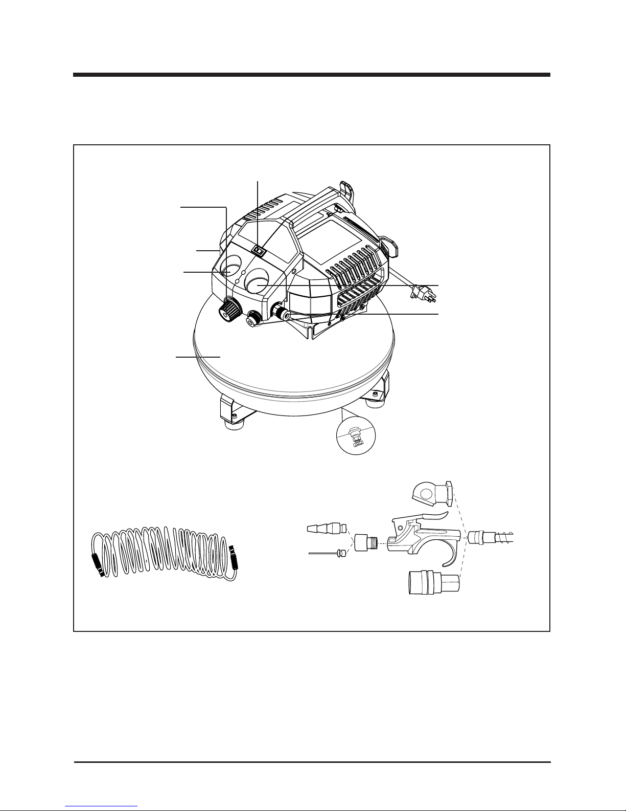
ACCESSORIES
SAVE THESE INSTRUCTIONS
FOR FUTURE USE
HOW TO PREVENT IT
HOW TO PREVENT IT
1
1
1
1
A portable compressor can fall
from a table, workbench, or roof
causing damage to the compressor
and could result in serious
injury or death to the operator.
Cut-In Pressure: While the motor
is off, air tank pressure drops as you
continue to use your accessory. When
the tank pressure drops to a certain
low level the motor will restart automatically.
The low pressure at which
the motor automatically restarts is
called "cut-in" pressure.
Cut-Out Pressure: When an air
compressor
is turned on and begins to
run, air pressure in the air tank begins
to build. It builds to a certain high
pressure before the motor automatically
shuts off, protecting your air tank
from pressure higher than its capacity.
The high pressure at which the motor
shuts off is called "cut-out" pressure.
Branch Circuit: Circuit carrying electricity
from electrical panel to outlet.
Become familiar with these terms
before operating the unit.
CFM: Cubic feet per minute.
SCFM: Standard cubic feet per minute;
a unit of measure of air delivery.
PSI: Pounds per square inch gauge;
a unit of measure pressure.
Code Certication: Products that
bear one or more of the following
marks: UL®*, CUL, ETL®*, CETL, have
been evaluated by OSHA certied
independent safety laboratories and
meet the applicable Standards for
Safety.
*UL® is a registered trademark of
Underwriters Laboratories and ETL®
is a registered trademark of Electrical
Testing Laboratories.
Includes: Recoil Hose, Blow gun, 1/4" Quick connector, Tire chuck, Ination needle
Blow gun adaptor, Tapered nozzle, Plumber's tape
Under some conditions and
duration of use, noise from this
product may contribute to hearing
loss.
Always operate commpressor in a
stable secure position to prevent
accidental movement of the unit.
Never operate compressor on a
roof or other elevated position.
Use additional air hose to reach
high locations.
Always wear certied safety
equipment: ANSI S12.6 (S3.19)
hearing protection.