DentalEZ istar User manual
OM-EZ721E


English


1
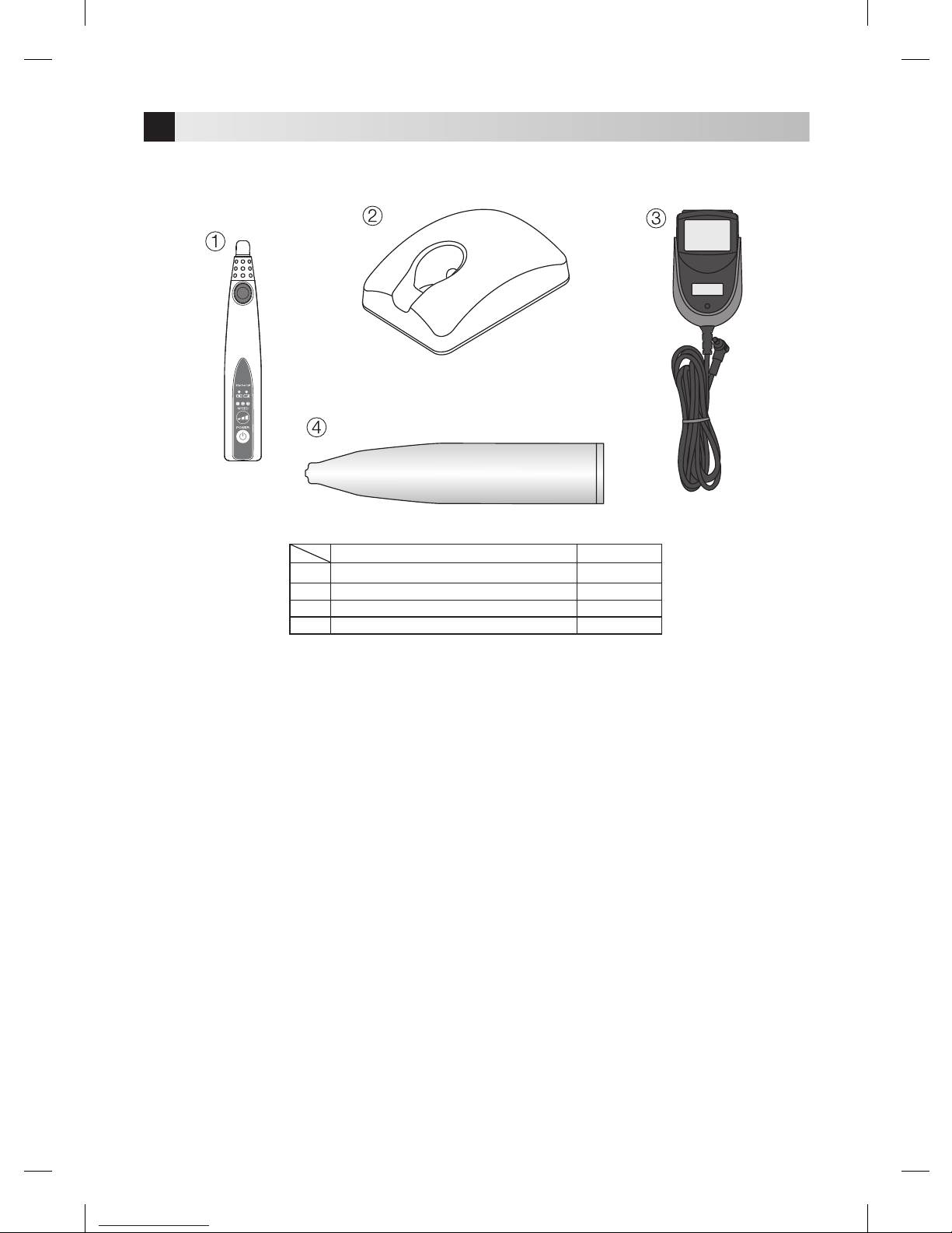
iStar

2
LIT
NOT LIT
iStar

3
iStar
4
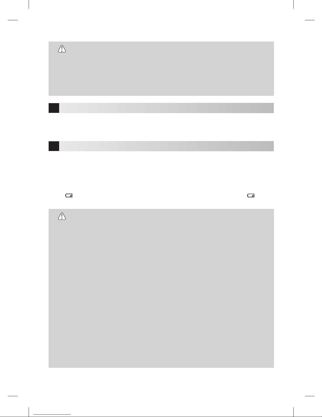
5

LIT
NOT LIT

6
7
8

9
10

11
12
13
-
14
15
16

17
18
Guidance and manufacturer's declaration - Electromagnetic Emissions
The product is intended for use in the electromagnetic environment specified below. The customer or the user of the product should assure that it is used in
such an environment.
Emissions test Compliance Electromagnetic environment - guidance
RF emissions
CISPR11
RF emissions
CISPR11
Harmonic emissions
IEC61000-3-2
Voltage fluctuations/flicker
emissions IEC 61000-3-3
Group 1
Class B
Not Applicable
Not Applicable
The product uses RF energy only for its internal function. Therefore, its RF emissions are very
low and are not likely to cause any interference in nearby electronic equipment.
The product is suitable for use in all establishments, including domestic establishments and
those directly connected to the public low-voltage power supply network that supplies buildings
used for domestic purposes.
Guidance and manufacturer's declaration - Electromagnetic Immunity
The product is intended for use in the electromagnetic environment specified below. The customer or the user of the product should assure that it is used in
such an environment.
NOTE: ‘Ut’ is the AC mains voltage prior to application of the test level.
Immunity test IEC60601 test level Electromagnetic environment - guidance
Electrostatic discharge (ESD)
IEC61000-4-2
Electrical fast transient/burst
IEC61000-4-4
Surge
IEC61000-4-5
Voltage dips, short
interruptions and voltage
variations on power supply
input lines
IEC61000-4-11
Power frequency
(50/60Hz)magnetic field
IEC61000-4-8
±(2, 4, 6)kV contact
±(2, 4, 8)kV air
±2kV for power supply lines
±1kV for input/output lines
±1kV line(s) to line(s)
±2kV line(s) to earth
<5% Ut (>95% dip in Ut)
for 0.5 cycles
40% Ut (60% dip in Ut)
for 5 cycles
70% Ut (30% dip in Ut)
for 25 cycles
<5% Ut (<95% dip in Ut)
for 5 sec
3 A/m
Compliance level
±(2, 4, 6)kV contact
±(2, 4, 8)kV air
±2kV for power supply lines
±1kV for input/output lines
±1kV line(s) to line(s)
±2kV line(s) to earth
<5% Ut (>95% dip in Ut)
for 0.5 cycles
40% Ut (60% dip in Ut)
for 5 cycles
70% Ut (30% dip in Ut)
for 25 cycles
<5% Ut (<95% dip in Ut)
for 5 sec
3 A/m
Floors should be wood, concrete or ceramic tile. If floors
are covered with synthetic material, the relative humidity
should be at least 30%.
Mains power quality should be that of a typical commercial
or hospital environment.
Mains power quality should be that of a typical commercial
or hospital environment.
Mains power quality should be that of a typical commercial
or hospital environment. If the user of the product
requires continued operation during power mains
interruptions, it is recommended that the product be
powered from an uninterruptible power supply or a
battery.
Power frequency magnetic fields should be at levels
characteristic of a typical location in a typical commercial
or hospital environment.

Guidance and manufacturer's declaration - Electromagnetic Immunity
The product is intended for use in the electromagnetic environment specified below. The customer or the user of the product should assure that it is used in
such an environment.
NOTE1: At 80MHz and 800MHz, the higher frequency range applies.
NOTE2:
These guidelines may not apply in all situations. Electromagnetic propagation is affected by absorption and reflection from structures, objects and people.
a: Field strengths from fixed transmitters, such as base stations for radio (cellular/cordless) telephones and land mobile radios, amateur radio, AM and FM
radio broadcast and TV broadcast cannot be predicted theoretically with accuracy. To assess the electromagnetic environment due to fixed RF transmitters,
an electromagnetic site survey should be considered. If the measured field strength in the location in which the product is used exceeds the applicable RF
compliance level stated above, the product should be observed to verify normal operation. If abnormal performance is observed, additional measures may
be necessary, such as reorienting or relocating the product.
b: Over the frequency range 150kHz to 80MHz, the field strength should be less than 3V/m.
Immunity test IEC60601 test level Electromagnetic environment - guidance
Conducted RF
IEC61000-4-6
Radiated RF
IEC61000-4-3
3Vrms
150kHz to 80MHz
3V/m
80MHz to 2.5GHz
Compliance level
3 Vrms
3 V/m
Portable and mobile RF communications equipment should be
used no closer to any part of the product, including cables, than
the recommended separation distance calculated from the
equation applicable to the frequency of the transmitter.
Recommended separation distance
= 1.2
= 1.2 80MHz to 800MHz
= 2.3 800MHz to 2.5GHz
Where is the maximum output power rating of the transmitter
in watts (W) according to the transmitter manufacturer, and ( ) is
the recommended separation distance in meters (m).
Field strengths from fixed RF transmitters as determined by an
electromagnetic site survey(a) should be less than the compliance
level in each frequency range(b).
Interference may occur in the vicinity of equipment
marked with the following symbol:
Complies withMaximum lengthCables and accessories
RF emissions, CISPR11
Electrostatic discharge (ESD):
Surge:
Voltage dips, short interruptions and voltage variations on power supply input
lines:
Conducted RF:
Radiated RF:
1.8mAC adaptor Class B/Group 1
IEC61000-4-2
IEC61000-4-5
IEC61000-4-11
IEC 61000-4-6
IEC61000-4-3
150kHz to 80MHz
Recommended separation distances between portable and mobile RF communications equipment and the product
The product is intended for use in an electromagnetic environment in which radiated RF disturbances are controlled. The customer or the user of the product
can help prevent electromagnetic interference by maintaining a minimum distance between portable and mobile RF communications equipment (transmitters)
and the product as recommended below, according to the maximum output power of the communications equipment.
For transmitters rated at a maximum output power not listed above, the recommended separation distance ‘ ’ in meters (m) can be estimated using the equation
applicable to the frequency of the transmitter, where ‘
’ is the maximum output power rating of the transmitter in watts (W) according to the transmitter manufacturer.
Rated maximum output power of transmitter
W800MHz to 2.5GHz
80MHz to 800MHz
NOTE1: At 80MHz and 800MHz, the higher frequency range applies.
NOTE2: These guidelines may not apply in all situations. Electromagnetic propagation is affected by absorption and reflection from structures, objects and
people.
Separation distance according to frequency of transmitter
m
0.01
0.1
1
10
100
0.12
0.38
1.2
3.8
12
0.12
0.38
1.2
3.8
12
0.23
0.73
2.3
7.3
23

C
2015-10-20
Table of contents


