Denyo DIS-390ES User manual

No. E48402 00204C
INSTRUCTION
INSTRUCTIONINSTRUCTION
I NSTRUCTION
MANUAL
MANUALMANUAL
MANUAL
DENYO
DENYODENYO
DENYO
ENGINE
ENGINEENGINE
ENGINE
COMPRESSOR
COMPRESSORCOMPRESSOR
COMPRESSOR
DIS-
DIS-DIS-
DIS- 390
390390
390ES
ESES
ES
390
390390
390ES-C
ES-CES-C
ES-C
390
390390
390ES-D
ES-DES-D
ES-D
Before using, be sure to read this manual for the sake of safety.
Be sure to observe the items under symbol marks
"
WARNING
"
and
"
CAUTION
"
for the sake of safety.
Always keep this manual at your machine for the sake of safety.
2-8-5, Nihonbashi-horidomecho, Chuo-ku, Tokyo, 103-8566, Japan

FOREWORD
* Your machine is a portable type engine compressor.
(Specifications: See p.54)
* Do not install, operate or repair this machine without reading this operating manual.
* This engine compressor (machine) must be operated by a person having sufficient
knowledge and skill for the sake of safety.
Notes on instruction manual
* This instruction manual explains correct operation and maintenance of the machine to
ensure its performance.
Incorrect handling of the machine may lead to a serious injury or decease.
Before using, be sure to read this manual carefully.
Particularly, the items under " Safety precautions" (See p.1 to p.8)
" WARNING" and " CAUTION" must be read thoroughly.
* Keep this manual in the case behind the rear door for future reference.
* Read the contents of the warranty card attached to the machine.
・If this manual becomes illegible by spot or damage, contact distributor or our office to
get
new manual.

- Contents -
1.Safety Precautions -------------------------------------------------------------------------------------
2.Construction ---------------------------------------------------------------------------------------------
2-1 Outline and part names ----------------------------------------------------------------------
2-2 Instrumental panel and part names ------------------------------------------------------
2-3 Meters ----------------------------------------------------------------------------------------------
2-4 Use of switc es and controllers -------------------------------------------------------------
3.Operation -------------------------------------------------------------------------------------------------
3-1 C ecking prior to operation ------------------------------------------------------------------
3-2 Starting --------------------------------------------------------------------------------------------
3-3 Starting under cold weat er -----------------------------------------------------------------
3-4 Precautions during operation ---------------------------------------------------------------
3-5 Stopping -------------------------------------------------------------------------------------------
3-6 Emergency stop and monitor display -------------------------------------------------------
4.Protection device ----------------------------------------------------------------------------------------
5.Lubrication oil, cooling water and fuel etc.--------------------------------------------------------
5-1 Engine oil ------------------------------------------------------------------------------------------
5-2 Cooling water -------------------------------------------------------------------------------------
5-3 Fuel --------------------------------------------------------------------------------------------------
5-4 Safety valve ---------------------------------------------------------------------------------------
5-5 Regulator ------------------------------------------------------------------------------------------
5-6 Compressor lube oil ----------------------------------------------------------------------------
6.Handling of battery ------------------------------------------------------------------------------------
6-1 Caution on battery c arge --------------------------------------------------------------------
6-2 Connection of booster cable, and installation ------------------------------------------
7.Periodical c ecking and maintenance ------------------------------------------------------------
7-1 Maintenance sc edule -------------------------------------------------------------------------
7-2 C ecking/first 50 ours --------------------------------------------------------------------
7-3 C ecking/every 100 ours --------------------------------------------------------------------
7-4 C ecking/every 250 ours --------------------------------------------------------------------
7-5 C ecking/every 500 ours --------------------------------------------------------------------
7-6 C ecking/every 1000 ours ------------------------------------------------------------------
7-7 C ecking/every 2000 ours ------------------------------------------------------------------
7-8 Table of periodical maintenance and c ecking -----------------------------------------
8.Trouble s ooting and Countermeasures ---------------------------------------------------------
9.Long - term storage ------------------------------------------------------------------------------------
10.Service data ---------------------------------------------------------------------------------------------
10-1 Specifications -----------------------------------------------------------------------------------
10-2 Outline drawing -------------------------------------------------------------------------------
10-3 Combined Piping Diagram -----------------------------------------------------------------
10-4 Engine wiring diagram --------------------------------------------------------------- ------
1
9
9
10
11
15
17
17
22
23
23
24
24
26
27
27
28
29
29
30
31
33
34
35
36
36
37
38
39
40
42
45
46
47
53
54
54
55
61
64

1
1.Safety Precautions
In order to ensure safe operation, the following symbols are used for explanation of the
machine operation.
The following symbols, found throughout this manual, alert you to potentially
dangerous conditions to the operator, service personnel, or the equipment.
WARNING:
This symbol refers to a hazard or unsafe practice which can result
in severe personal injury or death.
CAUTION:
This symbol refers to a hazard or unsafe practice which can result
in personal injury or product or property damage.
[Note] :
This symbols show handling precautions for effective
operation and many years of satisfactory operation.
Some of the items shown by CAUTION may also cause death or serious injury.
Be sure to observe all the items, as they are important for safe operation.
* If the machine is used by an outsider, you are requested to explain him correct
handling
and advise him to read this instruction manual carefully.
* Do not modify the machine at your discretion, as it affects the safety, performance or
the life of the machine.
* If the machine is modified or it is used incorrectly against this manual or unauthorized
parts are used, the warranty of manufacturer will become invalid.

2
Safety label
Safety labels are attached to the following positions of the machine.
* Keep these safety labels clean at all times.
* When safety labels are spoiled or lost, contact distributor or our office specifying the
nameplate No. shown below and ask for new ones.
1.Warning : Moving parts
(B9050 0050)
2.Caution : Hot surfaces
(E9042 0010)
3.Warning : Hot coolant
(B9051 0030)
4.Caution : Against exhaust gas
(B9052 0000)
5.Warning : Diesel fuel
(B9055 0070A)
6.Safety Instructions
(E9111 0120)
7.Caution : High pressure
(E9411 0110)
8.Caution : Residual pressure
(E9411 0120)
9.Safety Instructions on trailer
(E9111 0110)
3
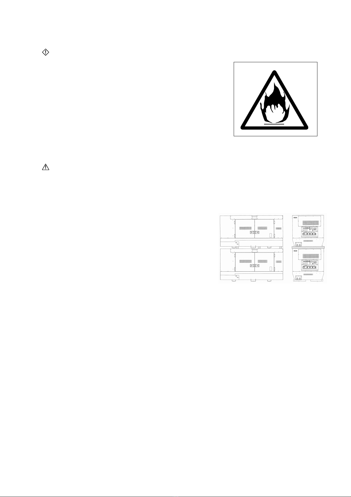
WARNING
ENGINE EXHAUST can kill.
■ Insufficient ventilation may lead to death due to
lack of oxygen or poisoning by exhaust gases.
* Do not use the machine in a place of poor ventilation
or in a place where exhaust gases stays.
* Do not use the machine indoors or in storehouse, tunnel,
ship hold, tank, etc. of poor ventilation.
* If it becomes necessary to use the machine in the
above places, the exhaust pipe should be extended
to a well ventilated place. In this case, use a ventilator
to ensure proper ventilation.
* Do not direct the exhaust outlet to nearby pedestrians
and houses.
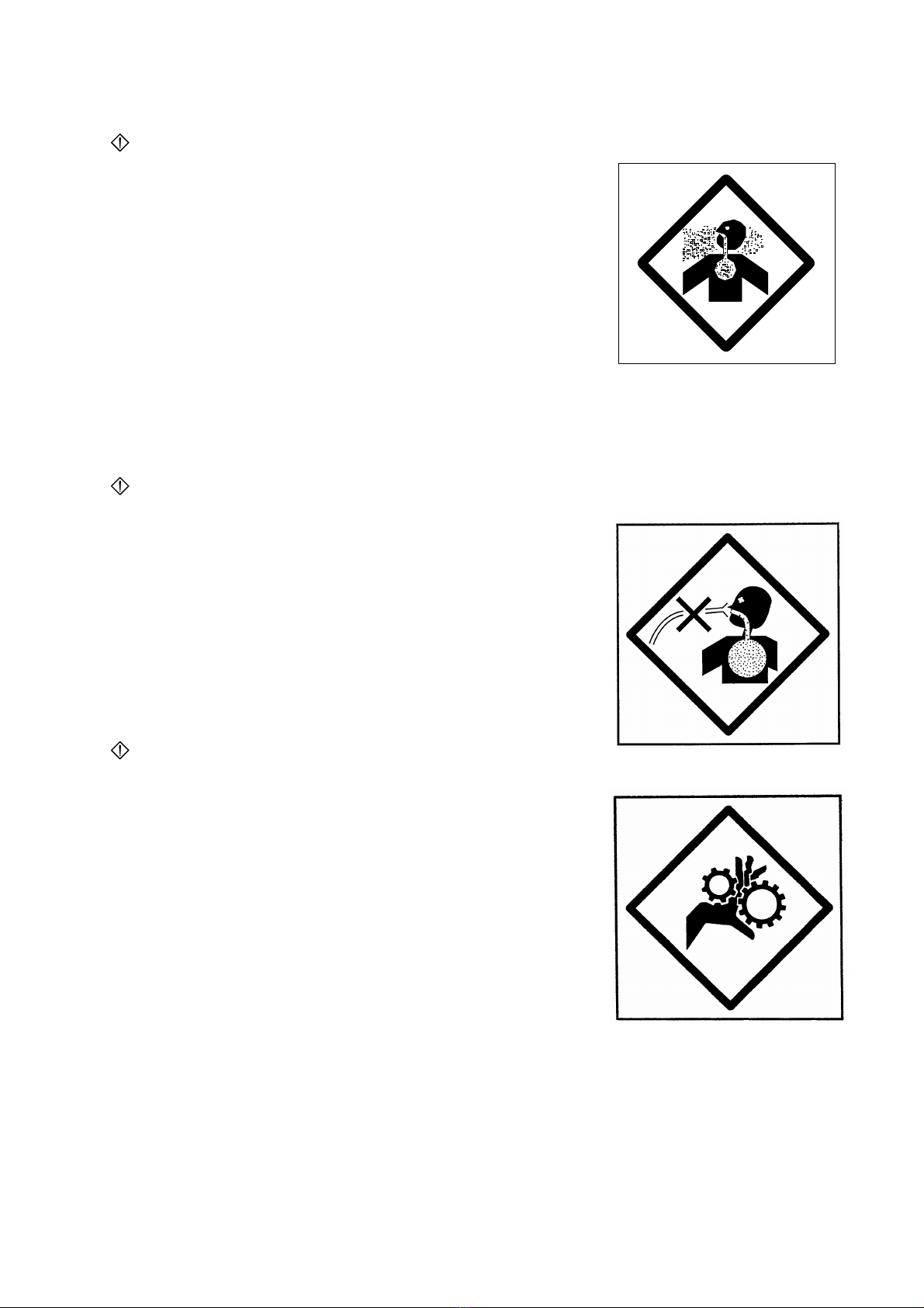
WARNING
THE AIR DELIVERED can kill.
■ Do not allow to breathe the air delivered
by compressor .Otherwise, it may result
in death accident. the compressor must
not be used for raising air pressure in a
room or for supplying air for diver's breathing.
WARNING
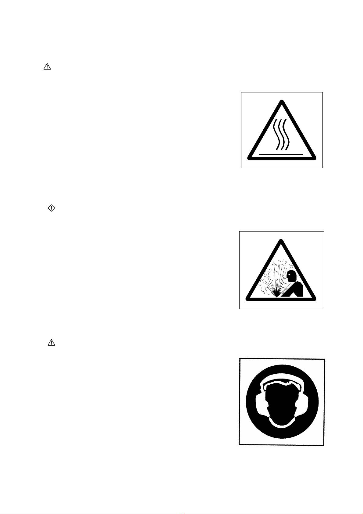
MOVING PARTS can cause severe injury.
■
Rotary uni
t which runs at a high speed is located
in the machine.
(Note that it is very dangerous if you touch it.)
* Be sure to close the door and lock it during operation.
* When the door needs to be opened during operation,
do not get your hands and head in the machine to
prevent them from being caught in the machine which
may lead to injury.
* When making check or maintenance of the machine,
be sure to stop the machine in advance.
4
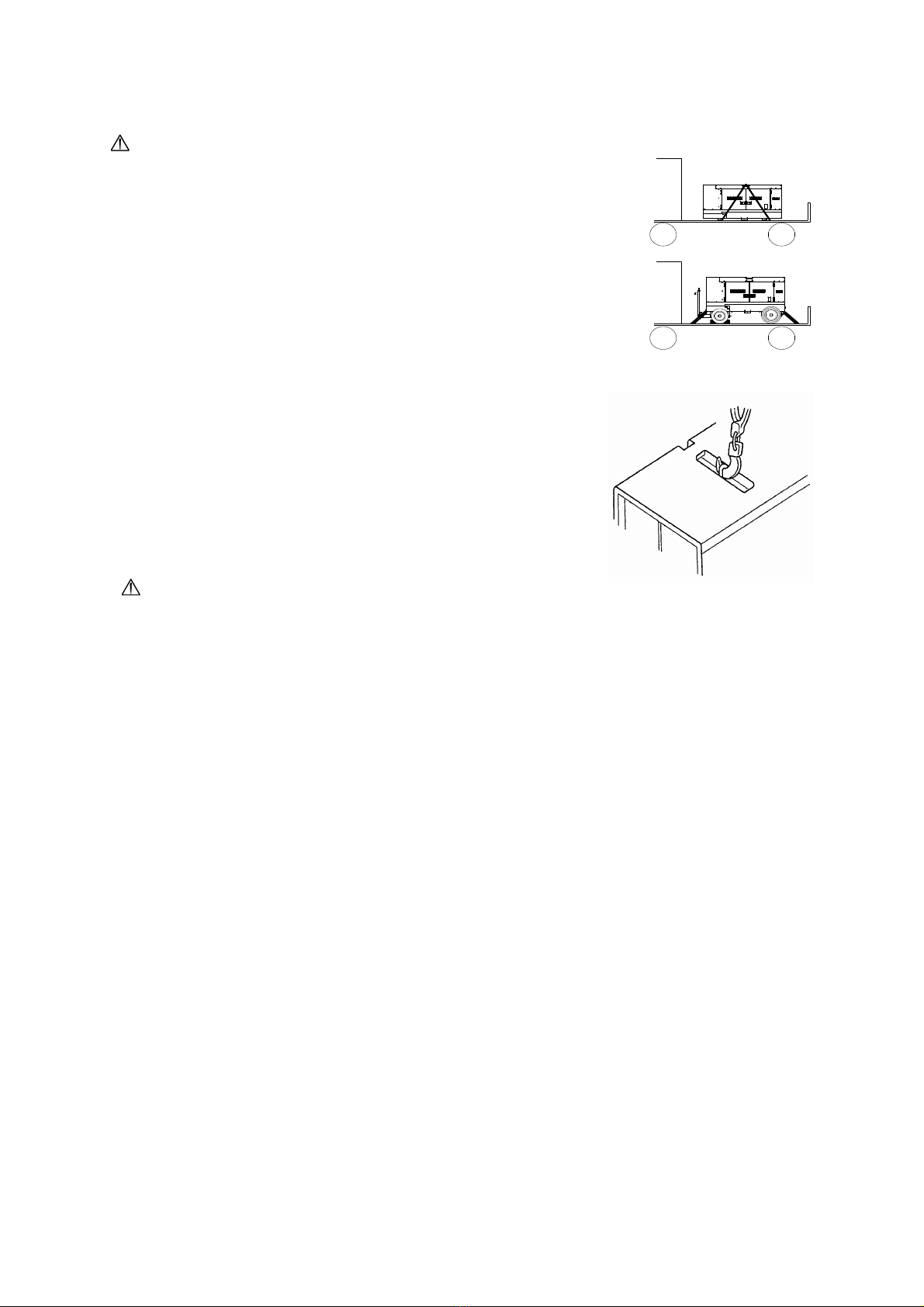
WARNING
DIESEL FUEL can cause fire or explosion.
■ Fuel and oil are flammable. Incorrect handling
results in danger of ignition or fire.
* When fuel needs to be supplied to the machine,
be sure to stop the engine. Refrain from smoking.
Keep the machine away from fire.
* Do not leave flammable objects (paper, wood chips,
etc.) and hazardous objects (oil, powder, etc.) near
the machine.
* Wipe off spilt fuel and oil.
CAUTION
Stacking
■ Improper stacking of machines may cause falling or dropping accidents.
When stacking other machines on this machine, be sure to observe the
following points.
* Check that the bonnet of the machine is free from
damage and that the fixing bolts are not loosened
and missing.
* Put the machine horizontally on a solid foundation
which withstands the weight of stacked machines.
* Machines can be stacked up to 2 stages.
The weight and size of stacked machines should
be less than those of this machine.
* Using square timbers as shown right, put each
machine making sure that the weight is even.
■
Do not operate the machines in the state of
stacking to prevent falling or dropping accidents.
5
CAUTION
HOT PARTS can burn skin.
■ High temperature units are located in the machine.
(Note that these units are very dangerous if they are
used incorrectly.)
* Be sure to close the door and lock it during operation.
* If the door needs to be opened during operation,
do not get your hands and head in the machine to
prevent unexpected burns.
* When making check or maintenance of the machine,
be sure to stop the machine.
* The bonnet is still hot even after the machine is
stopped.
Be careful until the engine is completely cooled.
WARNING
HOT COOLANT can cause severe scalds.
■ If the radiator cap is opened while the water
temperature is high, steam or hot water will
spout out.
* During operation or immediately after stopping the
machine, do not open the radiator cap while the
water temperature is high.
* When cooling water needs to be checked or supplied,
wait until the engine is cooled (50℃ or less as
measured with the water temperature gauge).
CAUTION
Noise
■
This machine generates large noise, if the door is
open. Surrounding to large noise may cause hearing
trouble.
* Close and lock the door during operation.
* If opening the door is necessary during operation,
be sure to put on the ear protector.

6
CAUTION
High pressure
■
Dangerous High Pressure. Never open the oil filler
port, while high pressure remains inside. Otherwise,
A serious injury can result. Be sure to stop engine and
release the inside pressure before filling oil.
CAUTION
High pressure remains
■
Dangerous Residual Pressure. Never take off
the pipings keeping residual pressure, for it can
cause a serious injury. Be sure to release the residual
pressure before taking off.
CAUTION
BATTERY
■ Battery generates flammable gases.
Improper handling may lead to explosion
or serious injury.
* Battery should be charged in a well ventilated
location. Otherwise, flammable gases are
accumulated which may be ignited and exploded.
* When connecting a booster cable, do not jumper
the terminals (+ and -). Otherwise, the flammable
gases generated from the battery may be ignited
and exploded by sparks.
* For maintenance of the machine, disconnect the
ground cable on the ground side.
■
The battery acid is dilute sulfuric acid. Improper
handling will cause unexpected burns.
* When the battery acid gets on your clothes or skin, wash it out with a large volume
of
water immediately. If it gets in your eyes, wash with a large volume of water
immediately and consult your doctor.
- In the worst case, it will put out your eyes.
■ For checking or handling of the battery, be sure to stop the engine and turn OFF the
battery switch in advance.
7
CAUTION
Transportation
■
Do not lift the machine at the support hook or the ladder
because it is not strong enough for lifting and may cause
a falling accident.
* When lifting the machine, use the hanger located at the
roof center.
* Keep out under the lifted machine.
■ Do not lift or do not transport the machine during
operation, as it may cause damage to the fan or
serious trouble.
* When loading the machine on the truck or the like,
fix the machine firmly by support hooks on the both
side.
The detail as machine size is referred to
「10-1. Specifications See p.54」
CAUTION
Operator
■ Do not operate the machine, if operator is tired too much or drinks some
alcohol
or take some drugs.
* Otherwise, it may cause unexpected accidents or injury.
■
During checking or maintenance, be sure to put on suitable clothes and protectors.
* Do not put on baggy clothes, necklace, etc., because they are easily caught by
projections which may cause injuries.

8
CAUTION
Run away
■ Be sure to set the wheel stoppers expect for moving.
Otherwise, the unit may move or run away and can
cause a serious accident.
CAUTION
Safety instructions on Trailer
Improper operating of the trailer can result in the accident to severe injury or death.
For moving or parking, be sure to keep the following instructions:
1. Place the unit on a level and hard ground. Placing on an inclined location may cause
free moving or tumbling down to injury.
2. Except for moving, securely pull the parking brake, if it is fitted, and always put
the wheel stoppers. For the 2-wheeled trailer, set up the standing bar or caster
to fix the unit securely.
3. For moving, remove the stoppers and release the parking brake if it is fitted.
Use the parking brake only for parking, and never use it for braking the unit when
transporting.
4. For moving, securely connect the unit to the towing system of the towing vehicle
which
should have an enough towing capability and should be driven by a qualified
driver.
5. Never move the unit at the towing speed of over 25km/h.
6. Put the unit on a truck for transporting the unit from a workshop.

9
2.Construction
2-1 Outline and part names
1. Instrumental panel
9. Compressor lube oil drain port
2. Air outlet valves
10. Engine lube oil drain port
3. Fuel inlet port
11. Coolant drain port
4. Lifting hook
12. After-cooler drain (ES-C/ES-D)
5. Rope hook
13. Compressor lube oil level gauge
6. Coolant inlet port
14. After-warmer drain (ES-D)
7. Exhaust gas outlet port
8. Fuel drain port
10
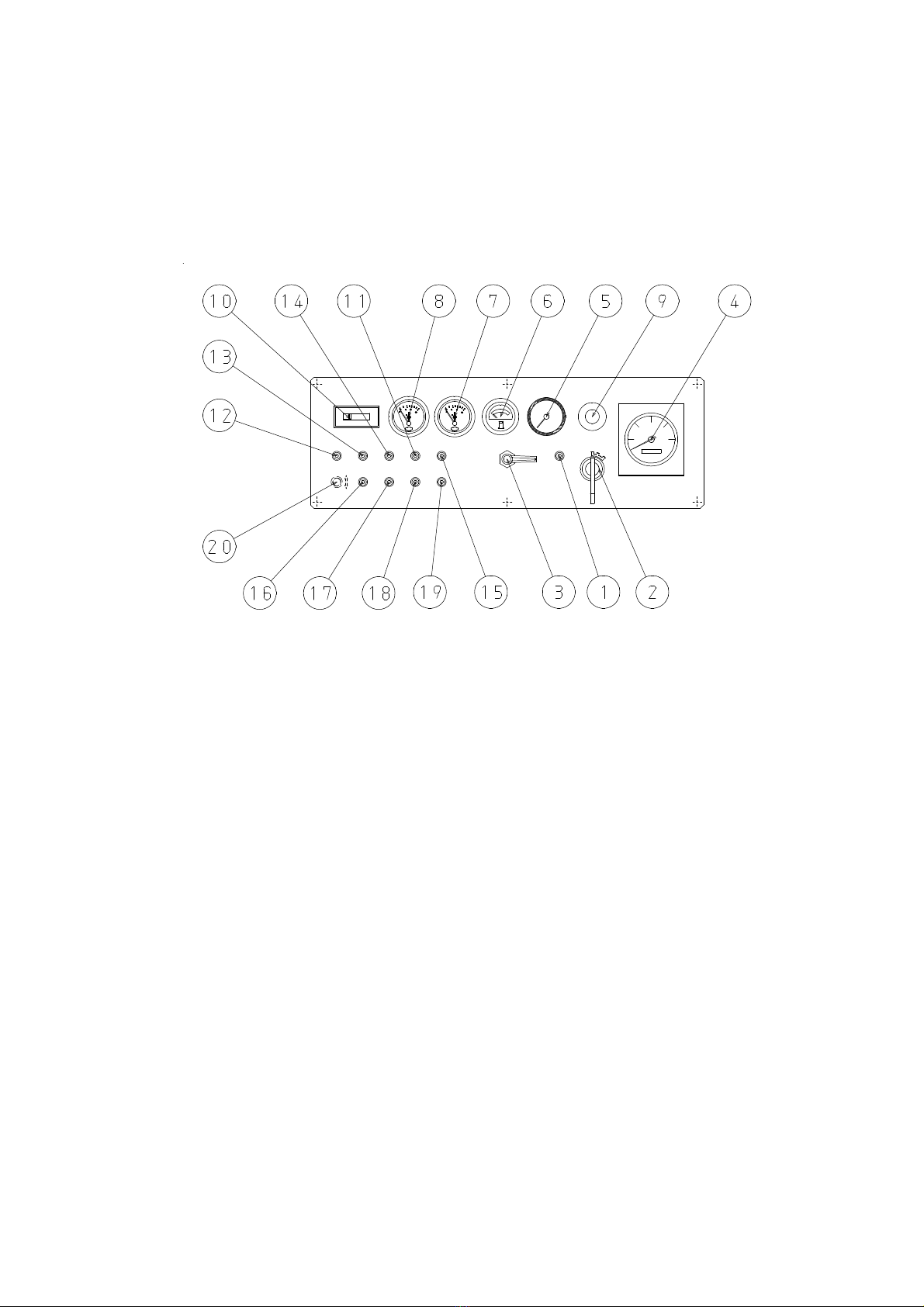
2-2 Instrumental panel and part names
The instruments panel contains all the meters, instruments and switches necessary for
operating the machine:
1. Preheat lamp
11. Engine lube oil pressure warning lamp
2. Starter switch
12. Water temperature warning lamp
3. Unloader valve
13. Charging warning lamp
4. Tachometer (within hour meter)
14. Discharge air temperature warning lamp
5. Delivery air pressure gauge
15. Engine low speed warning lamp
6. Fuel level gauge
16. Residual tank pressure warning lamp
7. Water temperature gauge
17. Compressor air filter warning lamp
8. Discharge air temperature gauge 18. Engine air filter warning lamp
9. Emergency stop button
19. Compressor oil filter warning lamp
10.
Oil separator indicator 20. Standard - remote change over switch
(Option).

11
2-3 Meters
Engine indicators
(1) Tachometer
This meter indicates the number of revolutions
of the engine.
(2) Hour meter
This meter indicates the total running time of the engine.
This meter is built in the tachometer.
(3) Water temperature gauge
This is normal when it indicates 82 to 95℃ during operation.
[Note]
If it indicates higher values, close air outlet valves.
The speed regulator will reduce engine speed to the idle
cycle, and wait until the temperature lowers.
(4
44
4) Fuel level gauge
This meter indicates the quantity of fuel in fuel tank.

12
Compressor indicators
(1) Delivery air pressure gauge
This meter indicates pressure of delivered air
by compressor.
(2) Discharge air temperature gauge
This meter indicates temperature of discharge air.
This is normal when it indicates 60 to 105℃ during operation.
[Note]
If it indicates higher values, close air outlet valves.
The speed regulator will reduce engine speed to
the idle cycle, and wait until the temperature lowers.

13
Indicator / warning lamps
(1) Oil separator indicator
When the Oil Separator Element is blinded, this
indicator draws near the red range.
While working, the green range shows its normality,
the red range shows it should be replaced.
(2) Engine air filter
When the engine air filter element is blinded, this lamp lit on.
Indicating that the element should be immediately cleaned or
replaced.
ENG.AIR FILTER
(3) Compressor air filter
When the compressor air filter element is blinded, this lamp
lit on. Indicating that the element should be immediately
cleaned or replaced.
COMP.AIR FILTER
(4) Residual tank pressure
When there is residual pressure in the oil chamber and
the engine is starting, this lamp lit on.
At this time, the engine can not start. Restart the engine
after confirming that the pressure gauge reads zero.
RESIDUAL TANK PRESS.
(5) Preheat lamp
When the starter switch is turned to the RUN position,
this lamp lit on.
When the preheat lamp lit off, it indicates that preheating is
PREHEAT completed.

14
(6) Engine low speed
This lamp lit on, if engine revolution failed abnormally.
If this lamp lit on during operation, the emergency stop device
immediately operates to shut down the engine automatically.
ENG.LOW SPEED
(7) Engine Oil
If the machine is in normally operation, this lamp lit off.
When the starter switch is turned to "RUN" position to start
the engine, the lamp lit on, and when the engine oil pressure
rises after start up, it lit off.
If this lamp lit on during operation, the emergency stop device
OIL PRESS.
immediately operates to shut down the engine automatically.
(8) Water temperature
This lamp lit on when the water temperature rises abnormally.
If the lamp lit on during operation, the emergency stop device
immediately operates to shut down the engine automatically.
WATER.TEMP
(9) Charging
When the battery charging is failured, this lamp lit on.
This lamp lit of, normal during operation.
CHARGE
(10) Discharge air temperature
This lamp lit on when the discharge air temperature rises
abnormally. If the lamp lit on during operation, the emergency
stop device immediately operates to shut down the engine
automatically.
DISCHARGE AIR TEMP.
(11) Compressor Oil filter
When the compressor oil filter element is blinded, this
lamplit on. Indicating that the element should be
immediately replaced.
COMP.OIL FILTER
15
2-4 Use of switches and controllers
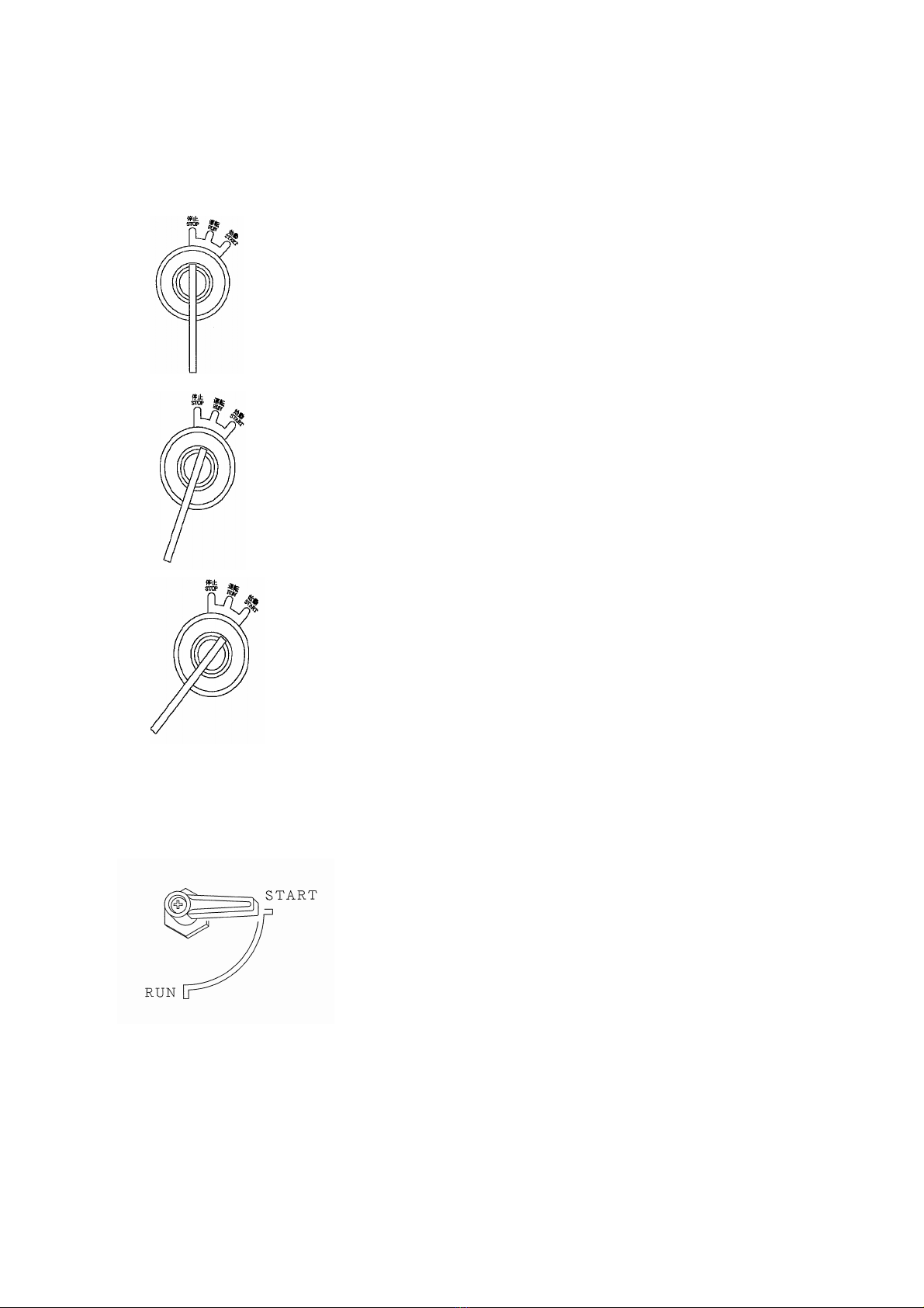
(1) Starter switch
Functions:
① STOP
This switch should be set in this position unless the
machine is in operation. The key can be inserted or pulled
out in this position.
② RUN
This switch should be set in this position when the
machine is in operation.
③ START
This is the position to start the engine. When your hand is
released from the key after starting, it is automatically set
to the "RUN" position.
(2) Unloader valve
Functions:
① START
This is the position to start the engine. When engine start,
warming up the engine for 5 to 10 minutes at the this
position.
② RUN
After warming up the engine ,set the unloader valve to the
"RUN" position. You can use delivered air by compressor

16
(3) Emergency stop button
Functions:
This is a pushbutton to stop the engine urgently on
emergency case. Do not push the button without emergency
case.

17
3.Operation
- From pre-start check to shut down -
Be sure to check the machine prior to starting.
1.. Checking prior to operation
2.. Starting
3.. Starting under cold weather
4.. Precautions during operation
5.. Stopping
6.. Emergency stop and monitor display
3-1 Checking prior to operation
WARNING
MOVING PARTS can cause severe injury.
■
Rotary uni
t which runs at a high speed is located
in the machine.
(Note that it is very dangerous if you touch it.)
* Be sure to close the door and lock it during operation.
* When making check or maintenance of the machine,
be sure to stop the machine in advance.
- To prevent unexpected trouble, be sure to check the following points.
(1) Check on engine lube oil
(2) Check on compressor lube oil
(3) Drain condensed water from oil chamber drain
(4) Check on radiator coolant
(5) Check on fan belt
(6) Check on fuel
(7) Check on battery fluid
(8) Check for loose parts
(9) Removal of foreign objects in machine
This manual suits for next models
2
Table of contents
Other Denyo Air Compressor manuals

Popular Air Compressor manuals by other brands

BorMann
BorMann BAT5100 manual

Vmac
Vmac VR70 installation manual

Powerex
Powerex AS-XXX product manual

Eaton Compressor
Eaton Compressor Polar Air PRS0050001 operating instructions

Ingersoll-Rand
Ingersoll-Rand P110 Operation and Maintenance Manual with Parts Catalogue

Air Techniques
Air Techniques AirStar AS60-400 Installation & operating instructions


