Air Techniques AirStar AS60-400 Manual

Installation & Operating
Instructions
AirStar Clinical Air Compressor
AS60, AS90, AS120, AS60-400
AS90-400 and AS120-400


Page
3Air Techniques, Inc.
Contents
Important Information
1� Notes on this documentation � � � � � � � � � � � � � � � � 4
1�1 Warnings and symbols � � � � � � � � � � � � � � � � 4
1�2 Notes concerning trade marks, brand names
etc� � � � � � � � � � � � � � � � � � � � � � � � � � � � � � � 4
1�3 Further documentation � � � � � � � � � � � � � � � � 4
2� Safety � � � � � � � � � � � � � � � � � � � � � � � � � � � � � � � � 4
2�1 Intended Use � � � � � � � � � � � � � � � � � � � � � � � 4
2�2 Incorrect Usage � � � � � � � � � � � � � � � � � � � � � 5
2�3 General safety notes � � � � � � � � � � � � � � � � � � 5
2�4 Qualified staff � � � � � � � � � � � � � � � � � � � � � � 5
2�5 Protection from electric shock � � � � � � � � � � � 5
2�6 Use original parts � � � � � � � � � � � � � � � � � � � � 5
2�7 Transport � � � � � � � � � � � � � � � � � � � � � � � � � � 5
2�8 Disposal � � � � � � � � � � � � � � � � � � � � � � � � � � 5
Product description
3� Overview � � � � � � � � � � � � � � � � � � � � � � � � � � � � � 6
3�1 Delivery contents � � � � � � � � � � � � � � � � � � � � 6
3�2 Accessories� � � � � � � � � � � � � � � � � � � � � � � � � �
3�3 Working parts and spare parts � � � � � � � � � � � 6
4� Technical data � � � � � � � � � � � � � � � � � � � � � � � � � � 7
4�1 Ambient conditions � � � � � � � � � � � � � � � � � � � 8
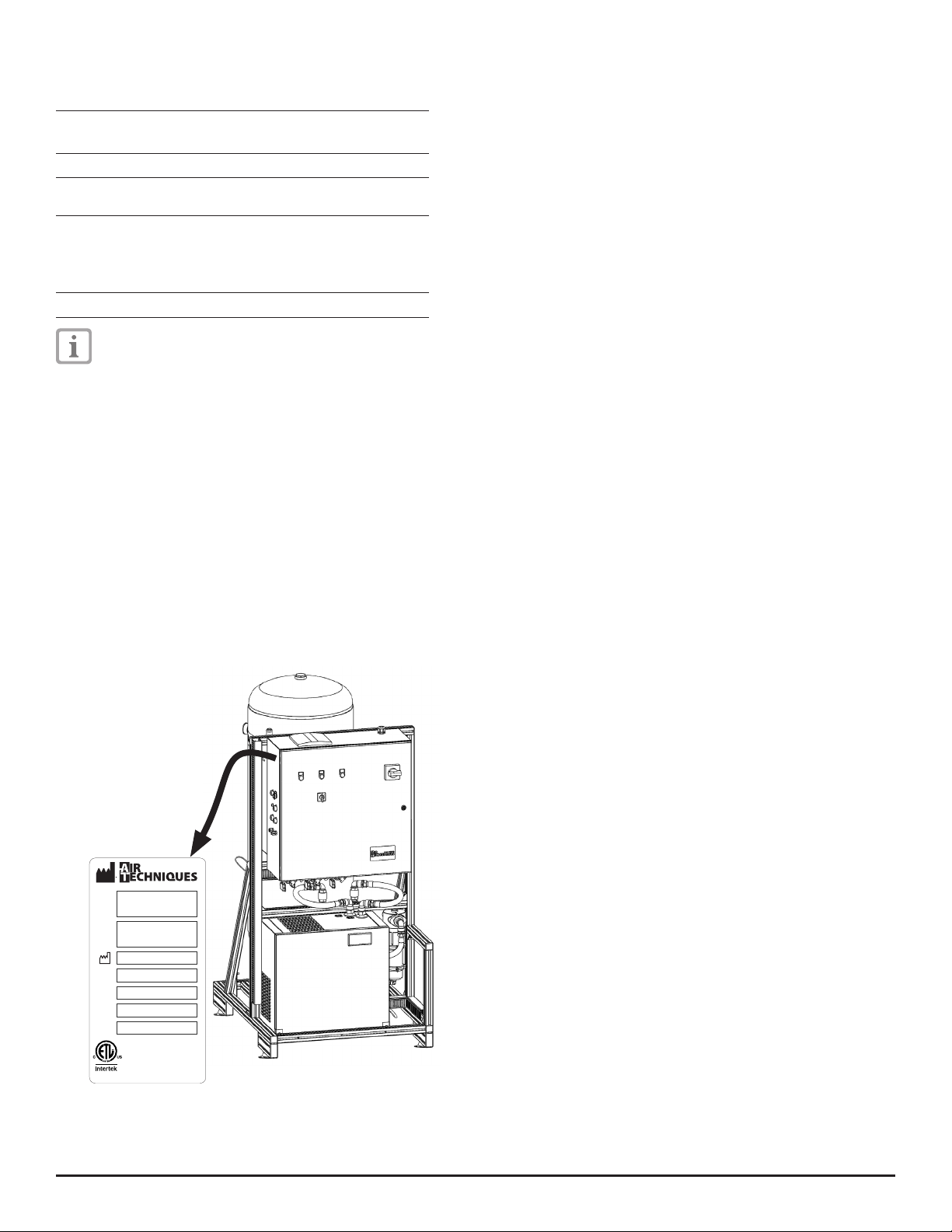
4�2 Model identification plate � � � � � � � � � � � � � � 8
4�3 Declaration of conformity � � � � � � � � � � � � � � 8
5� Function � � � � � � � � � � � � � � � � � � � � � � � � � � � � � � 9
5�1 Start operation � � � � � � � � � � � � � � � � � � � � � 11
5�2 Normal operation � � � � � � � � � � � � � � � � � � � 11
5�3 Emergency mode � � � � � � � � � � � � � � � � � � � 11
Mounting
6� General Notes � � � � � � � � � � � � � � � � � � � � � � � � � 12
6�1 Compressed air system requirements � � � � � 12
6�2 Set up in medical supply equipment � � � � � � 12
7� Transport � � � � � � � � � � � � � � � � � � � � � � � � � � � � � 12
8� Set-up � � � � � � � � � � � � � � � � � � � � � � � � � � � � � � � 12
8�1 Set-up location � � � � � � � � � � � � � � � � � � � � � 12
8�2 Module layout � � � � � � � � � � � � � � � � � � � � � 12
8�3 Set up and secure modules � � � � � � � � � � � � 12
9� Installation � � � � � � � � � � � � � � � � � � � � � � � � � � � 13
9�1 Connect the compressed air connection to
the cyclone separator � � � � � � � � � � � � � � � � 13
9�2 Connect the pressure tank to the com-
pressed air supply net � � � � � � � � � � � � � � � � 13
9�3 Connect the condensate drain outlet to the
waste water system � � � � � � � � � � � � � � � � � � 14
10 Electrical Connection � � � � � � � � � � � � � � � � � � � � 14
10�1 Electrical connection and safety � � � � � � 14
10�2 Connecting modules � � � � � � � � � � � � � � 14
10�3 Connection line dimensions � � � � � � � � � 14
10�4 Match motor protection switch to net-
work frequency � � � � � � � � � � � � � � � � � � 14
10�5 Connect control unit to the mains power
supply � � � � � � � � � � � � � � � � � � � � � � � � 14
11 Initial start-up � � � � � � � � � � � � � � � � � � � � � � � � � 15
11�1 Switching on compressed air station � � � 15
11�2 Choose operational mode � � � � � � � � � � 15
11�3 Document acceptance test � � � � � � � � � � 15
11�4 Measuring dew point (optional) � � � � � � � 15
Use
12 Activating emergency mode � � � � � � � � � � � � � � � 16
13 Decoupling a single compressor generator � � � � � 16
14 Fault rectification � � � � � � � � � � � � � � � � � � � � � � � 16
15 Maintenance � � � � � � � � � � � � � � � � � � � � � � � � � � 17
15�1 Maintenance plan � � � � � � � � � � � � � � � � 17
15�2 Maintenance � � � � � � � � � � � � � � � � � � � � 18
Trouble-shooting
16 Tips for Operators and Technicians � � � � � � � � � � 19
16�1 Faults that appear on the display panel � 19
16�2 Further messages at display panel � � � � � 20
Warranty� � � � � � � � � � � � � � � � � � � � � � � � � � � � � � � � 23
Warranty registration � � � � � � � � � � � � � � � � � � � � � � � 23

Air Techniques, Inc.
Page
4
Important Information
1 Notes on this documentation
These Installation and Operating Instructions are a basic
component to the appliance� They conform to the model
type of the appliance and represent the state of technol-
ogy at the time of manufacture and initial use�
Air Techniques can accept no responsibility and
no liability where the instructions and notes
contained within these Installation and Operating
Instructions are not observed nor guarantee the
safe and proper operation of the appliance�
1�1 Warnings and symbols
Warnings
Any warnings in this document are designed to draw
attention to possible injury to persons or to danger to
property�
They are marked with the following warning symbols:
General warning symbol
Warning - dangerous electrical voltage
Warning - hot surfaces
Warning - the unit starts up automatically
The warnings are built up as follows:
SIGNAL WORD
Description of type and source of danger
Here you will find the possible consequences of
ignoring the warning�
•Observe these steps to avoid possible danger�
The signal words denote four different warning levels:
DANGER Extreme danger which may result in
serious injury or death
WARNING Possible danger which could result in
serious injury or death
CAUTION Possible danger which could result in
minor injury
IMPORTANT Possible danger which could result in
serious damage
Further symbols
The following symbols are used within this document
and on the actual appliance:
Notes, e�g� special instructions concerning effi-
cient usage of the device
Consult Instructions for Use�
Dispose of according to UL and CSA directive
Date of manufacture
Wear ear protectors
Earthed wire connection
Air
4005460
with respect to electrical shock, re, mechanical and other
specied hazards only in accordance with
UL-508A, CAN/CSA Std. C22.2 No. 286
1�2 Notes concerning trade marks, brand
names etc�
All switches, processes, names, software and appliances
mentioned here are protected under copyright�
Making copies of the Installation and Operating Instructions,
or parts thereof, is only possible with the written approval
of Air Techniques�
1�3 Further documentation
All information and instructions concerning the refrigerant
type dryer are contained in the Atlas Copco FD Series dryer
manual supplied�
2 Safety
Air Techniques has designed and constructed this
appliance in such a way that under correct usage the
product is perfectly safe to use� However, there is always
a minimum risk�
For this reason, please observe the following notes
carefully�
2�1 Intended Use
The compressed air station is designed to supply com-
pressed air in order to operate dental units or for similar
applications� The compressed air station has been designed
for operation in dry, ventilated rooms� See Section 4�1 for
environmental storage and operating conditions�

Page
5Air Techniques, Inc.
2�2 Incorrect Usage
WARNING
Risk of explosion caused by flammable materials
•Do not operate the appliance in any rooms in
which flammable mixtures may be present, e�g�
in operating rooms�
The compressed air station must not be used in operat-
ing areas, for the operation of respiratory equipment or
other similar equipment�
Do not operate the compressed air station in wet or
damp rooms or environments� See Section 4�1 for envi-
ronmental storage and operating conditions�
Any usage of the appliance above and beyond the cor-
rect usage described in this documentation is considered
to be incorrect usage� Air Techniques cannot be held
liable for any damage or injury resulting from incorrect
usage�
2�3 General safety notes
•When operating this appliance always observe all
guidelines, laws, and other rules and regulations which
are applicable at the site of operation�
•Check the function and condition carefully every time
before using the appliance�
•Do not convert or change the appliance in any way�
•Carefully observe the Installation and Operating
Instructions�
•Make the Installation and Operating Instructions
available to the person operating the appliance at all
times�
•Wear ear protectors for all work where the unit must
be started up (e�g� initial start-up, maintenance)�
2�4 Qualified staff
Operation
Persons who are expected to operate the appliance must
be able to guarantee safe and correct operation as a
result of their training and their experience�
•Every person operating the device must be trained in
its handling�
Installation and repair and maintenance
•Installation, resetting, alterations, adding of extensions
and repairs must be carried out by Air Techniques or
by person(s) specifically authorized by Air Techniques�
•Ensure electrical connections are carried out by a
suitably qualified licensed electrician�
2�5 Protection from electric shock
• When working with the appliance observe the appropriate
electrical safety procedures�
• Immediately replace any damaged lines and connections�
2�6 Use original parts
•Only parts specified by Air Techniques or specifically
approved accessories may be used with this appliance�
•Use only original working parts and spare parts�
Air Techniques accepts no liability for damage
or injury caused by using accessories, special
accessories or parts other than original working
parts and spare parts which were not specifically
approved by the manufacturer�
2�7 Transport
The original packaging provides the optimum protection
for the appliance during transport�
Air Techniques accepts no liability for damage
caused by using inadequate packaging for transport
even if this is during the warranty period�
• Only transport the unit secured to the pallet in its original
packaging�
•Transport the unit using a forklift truck or lifting device�
•Keep the packaging safely out of the reach of children�
2�8 Disposal
Appliance
•Before committing to waste disposal, open the safety
valve and release all the compressed air from the
pressure tank�
•If you have any questions concerning the correct dis-
posal of this appliance please contact Air Techniques
directly or contact your local dealer�

Air Techniques, Inc.
Page
6
Product description
3 Overview
The compressed air station consists of two separate mod-
ules and a transformer when applicable (not shown):
- Control module, consisting of pressure tank, dryer and
controller
- Compressor module, consisting of 2, 3 or 4 compres-
sor aggregates
Fig� 1: AS120
1 Control module
2 Compressor module
3�1 Delivery contents
AS60
- Control module
- Compressor module with 2 compressor aggregates
- Connecting cables and hoses
- Mounting materials
- Installation and Operating Instructions
AS90
- Control module
- Compressor module with 3 compressor aggregates
- Connecting cables and hoses
- Mounting materials
- Installation and Operating Instructions
AS120
- Control module
- Compressor module with 4 compressor aggregates
- Connecting cables and hoses
- Mounting materials
- Installation and Operating Instructions
AS60-400
- Control module
- Compressor module with 2 compressor aggregates
- Boost transformer
- Connecting cables and hoses
- Mounting materials
- Installation and Operating Instructions
AS90-400
- Control module
- Compressor module with 3 compressor aggregates
- Boost transformer
- Connecting cables and hoses
- Mounting materials
- Installation and Operating Instructions
AS120-400
- Control module
- Compressor module with 4 compressor aggregates
- Boost transformer
- Connecting cables and hoses
- Mounting materials
- Installation and Operation Instructions
3�2 Accessories
The following articles are necessary to operate the de-
vice depending on particular application:
Display panel � � � � � � � � � � � � � � � �E5119
Switch (8-port)� � � � � � � � � � � � � � � �E5186
Gateway� � � � � � � � � � � � � � � � � � � �E5188
3�3 Working parts and spare parts
The following parts are subject to wear and tear and
should be changed at regular intervals (see section
Maintenance):
Bacterial Filter � � � � � � � � � � � � � � � � � � � � � E5131
Information concerning spare parts can be found
by contacting your authorized dealer or Air Tech-
niques�

Page
7Air Techniques, Inc.
4 Technical data
Model AS60 AS90 AS120
Number of compressor generators 2 3 4
Max Users @ 60% 60 90 120
Max Simultaneous Users @ 100% 40 60 80
Operating Voltage V3 ~480 VAC
Electrical frequency Hz 60 60 60
Power consumption hp / kW 15 / 11 22�5 / 16�5 30 / 22
Current consumption (400 VAC / 480 VAC) A39 / 32 54 / 45 68 / 56
Branch circuit breaker (400 VAC / 480 VAC) A50 / 40 70 / 50 90 / 60
Minimum wire gauge of electrical
supply line* (400 VAC / 480 VAC)
AWG 8 / 8 4 / 6 3 / 4
RPM min-1 1800
Circuit Breaker type IP 20
Protection class 1
Duty cycle %100
Switch-on pressure (factory setting) psi
(bar)
102 / 109
(7 / 7�5)
94 / 102 / 109
(6�5 / 7 / 7�5)
87 / 94 / 102 / 109
(6 / 6�5 / 7 / 7�5)
Cut off pressure (factory setting) psi
(bar)
109 / 116
(7�5 / 8)
102 / 109 / 116
(7 / 7�5 / 8)
94 / 102 / 109 / 116
(6�5 / 7 / 7�5 / 8)
Safety valve settings psi
(bar)
10
145
Tank volume Gal / L 120 / 454
Delivery rate at 85 psi (6 bar)
100 psi (7 bar)
CFM /
LPM
60 / 1,700
56�6 / 1,600
90 / 2,550
84�8 / 2,400
120 / 3,400
113�1 / 3,200
Noise levels at or 73 psi (5 bar) **
- without noise reducing hood dB(A) 88 91 93
System Weight
- compressor module
- control module
lbs (kg)
lbs (kg)
505 (229)
700 (318)
835 (379)
700 (318)
1055 (479)
700 (318)
Shipping Weight
- compressor module
- control module
lbs (kg)
lbs (kg)
605 (275)
850 (386)
940 (425)
850 (386)
11505 (522)
850 (386)
Connections
- compressed air outlet
- condensate inch or mm
1 inch NPT internal thread
0�8" / 20
Volume of condensate �05 gallon or 200ml or per condensate drain cycle
depend on rel� Humidity and Temperature
Required room ventilation CFM 530 742 989
Dimensions (H x W x D)
- compressor module
- compressor module and pallet
- control module
- control module and pallet
in�
(cm)
in�
(cm)
in�
(cm)
in�
(cm)
38x51x39
(95x129x99)
44x55x43
(110x138x109)
82x39x51
(209x99x129)
93x43x55
(235x109x138)
71x51x39
(180x129x99)
75x55x43
(195x138x109)
82x39x51
(209x99x129)
93x43x55
(235x109x138)
71x51x39
(180x129x99)
(75x55x43)
(195x138x109)
82x39x51
(209x99x129)
93x43x55
(235x109x138)
Total required space in�
(cm)
86x138x111
(220x350x280)
86x138x111
(220x350x28)
86x138x111
(220x350x280)
* The cross-section of the electric supply cable must be matched to the current consumption, length of supply line and
local situations (see 10�3 Connection line dimensions)
** According to EN ISO 1680 Noise emissions; measured in a sound-proofed room� The values are average values with
tolerances of approximately ±1�5 dB(A)�

Air Techniques, Inc.
Page
8
4�1 Ambient conditions
Ambient conditions for storage and transport
Temperature °F/°C 32/0 to
140/+60
Relative Humidity %max� 95
Ambient conditions for operating
Temperature °F/°C 50/+10 to
104/+40
Rel� Humidity %max� 70
The ideal ambient temperature for the life-span
of the compressed air station and low condensed
water buildup is 77 °F or 25 °C�
4�2 Model identification plate
Each module is fitted with a model identification plate�
4�3 Statement of conformity
Name of manufacturer: Air Techniques
Name of unit: AirStar Clinical Air
Compressor
Models: AS60
AS90
AS120
AS60-400
AS90-400
AS120-400
Control panel
Conforms to UL508A, the UL Standard for Construction
Of Industrial Control Panels�
Air Receiver Tank
Conforms to ASME Boiler and Pressure Vessel Code
Rules Section VIII, Division I�
Fig� 2� System model identification plate�
1
1
2
2
9
9
5
5
W
W
a
a
l
l
t
t
W
W
h
h
i
i
t
t
m
m
a
a
n
n
R
R
o
o
a
a
d
d
M
M
e
e
l
l
v
v
i
i
l
l
l
l
e
e
,
,
N
N
Y
Y
1
1
1
1
7
7
4
4
7
7
-
-
3
3
0
0
6
6
2
2
REF
SN
VOLTS
AMPS
FREQ.
SN BARCODE HERE
REF BARCODE HERE
READABLE TEXT HERE
READABLE TEXT HERE
MANUF. DATE HERE
P/N 09150 Rev. F
HP
4005460
CONFORMS TO
UL STD. 508A
CERTIFIED TO
CAN/CSA Std. C22.2 N O. 286

Page
9Air Techniques, Inc.
5 Function
The compressed air station produces oil-free, dry and filtered compressed air which is used to operate dental units,
simulation stations ( phantom places ) and similar�
The display panel is used to configure the operation of the device, monitor the operating status (e�g� fault reports) and
troubleshoot faults�
Fig� 3: Compressed air station
19
18
17
1
2
3
4
9
16
6
7
8
5
15
20
10
13
14
12
11

Air Techniques, Inc.
Page
10
Fig� 4: Pneumatic layout plan
1 Compressor aggregate safety valve
2 Compressor aggregate shutoff valve
3 Compressor aggregate
4 Pressure relief valve
5 Pressure tank
6 Tank safety valve 145 psi (10 bar)
7 Control connection
8 Tank connection to air network ( 1 inch NPT)
9 Condensate drain
10 Condensate separator drainage
11 Pressure sensor
12 Refrigerant dryer bypass valve
13 Refrigerant dryer valve outlet
14 Refrigerant dryer valve inlet
15 Solenoid relief valve
16 Bacterial intake filter
17 Cyclone separator
18 Refrigerant dryer
19 Control unit with PLC
20 Pressure gauge
1
3
17
4
5
6
8
16
18
20 11
9
15
2
13 14
12
10

Page
11Air Techniques, Inc.
While the compressor aggregate is in operation the accumu-
lating condensate is separated by being conveyed through
the cyclone separator and, in a second step, through a
refrigerant dryer and then separated to the waste water
system� This process is carried out automatically using a
valve in the cyclone separator and the refrigerant dryer
controller, depending on the level present�
A special load controller monitors the compressor aggregate
operation and implements an alternation of compressor
operation on a rolling system� The alternation is carried
out according to the number of operating hours each
individual compressor aggregate has performed�
The pressure in the tank can be read off using a pressure
gauge and also at the display panel�
Auxiliary operation
Depending on the amount of compressed air required and
the particular set up of the compressed air network it may
be necessary for two (or more) compressed air stations
to work together on one network� In this particular set up
one compressed air station operates in main operation,
the other(s) in auxiliary operation�
The settings for auxiliary operation are carried out on
initial set up and configuration of the complete unit using
the display panel� In auxiliary operation the control range
for cutting in and cutting off pressure for the compressed
air station is lowered by 1�5 psi (0�1 bar)� In this way the
compressed air station aggregates switch in main and
auxiliary operation alternately on and off�
5�3 Emergency mode
Emergency mode can only be used for short periods in
order to maintain an emergency supply of compressed
air in the cases of a possible defect in the system�
Turning the switch (4) to the Emergency mode setting "1"
switches on the first compressor aggregate and it starts
up in pressure free state�
After approximately 3 seconds the switch (4) can be rotated to
position "2"� The solenoid valve opens the pressure line and
the compressor aggregate begins to supply the pressure tank�
The compressor aggregate then runs in continuous operation�
The alternation of aggregates no longer takes place�
When no air is taken from the tank, the pressure in the tank
increases to 145 psi (10 bar) and will be maintained at this
level by the opening of the safety valve� The safety valve
produces a loud venting noise when it is in the open position�
Fig� 5: Control unit
1 Red LED "Fault"
2 Blue button "Reset"
3 Green LED “Run”
4 Emergency mode switch
5 Main power switch
5�1 Start operation
After switching on at the main power switch of the control
unit the refrigerant type dryer is switched on and cools
the heat exchanger to its normal operating temperature�
Depending on the actual ambient temperature this cooling
can take up to 3 minutes (see the temperature display on the
refrigerant dryer)� After approx� 60 seconds the controller
switches on the first compressor aggregate� At about 3
seconds the next compressor aggregate will be switched
on� A sensor monitors the pressure inside the tank, which
is shown by the display� Upon reaching the set pressure in
the controller (see section Technical Data) the aggregates
will be turned off sequentially�
5�2 Normal operation
A sensor monitors the pressure in the tank vessel� When
compressed air is taken from the pressure tank, the pressure
within the tank falls� At 109 psi (7�5 bar) the first compressor
aggregate switches on� If the pressure within the tank continues
to fall, then further compressor aggregate are switched on
consecutively according to the switch-on pressures set (see
4 Technical data)�
Each compressor aggregate starts up in a pressure free
state� After approximately 3 seconds the solenoid relief
valve opens the pressure line and the aggregate begins
to supply the pressure tank�
When the pressure within the tank rises, the compressor
aggregates are switched off one after the other as soon
as the preset cut off pressure of 116 psi (8 bar) has been
reached (see 4 Technical data)�
When more compressed air is taken from the tank the pressure
falls and the next aggregate switches on automatically� When
the tank pressure falls below 15 psi (1 bar), the compressed
air station switches over to emergency mode (one compressor
aggregate remains in continuous operation)�
1 3
25
4

Air Techniques, Inc.
Page
12
Mounting
6 General Notes
6�1 Compressed air system requirements
The compressed air network to which the compressed
air system is connected must be set up so that there is a
maximum pressure of 145 psi (10 bar)�
6�2 Set up equipment
•Before installation ensure that the compressed air
available is suitable to satisfy all requirements for its
particular usage�
•Unit classification and evaluation of conformity must
be carried out on installation by the manufacturer of
the end product�
7 Transport
WARNING
During transport of the compressed air system
parts can come loose�
•Only transport the compressed air system with
no pressure in tank�
•Before transport bleed off all compressed air
from the pressure tank and the pressure hoses�
8 Set-up
8�1 Set-up location
Set-up location requirements:
- dry and well ventilated room
(for required ventilation see 4 Technical data)
- ambient temperature range of 50 and 104° F�
(+10 and +40 °C)
- max� 70 % room air relative humidity
• Installation in purpose built rooms, e�g� boiler room, must
be checked against building regulations beforehand�
•Do not operate the units in damp or wet environments�
•Clearly indicate that the room may only be entered by
staff wearing ear protectors�
Some 70% of the electrical energy taken up by the com-
pressed air station is converted into heat and given off
to the surroundings�
•If it is possible that the required room temperatures will
be exceeded then ventilation or some form of cooling
will be required and must be installed�
•The compressor module can be set up either left or
right of the control module�
•Maintain a distance between the modules of approxi-
mately 20 inches (50 cm) to allow sufficient space for
maintenance�
8�2 Module layout
Fig� 6: Distance between control and compressor mod-
ule
8�3 Set up and secure modules
The mounting materials are supplied in the scope
of delivery�
•Loosen the modules from the pallets (undo transporta-
tion safety devices)�
•Use a forklift truck or lifting equipment to move both
modules to the location chosen for set up�
•Drill required holes into the floors for the fixtures�
•Insert plugs�
•Secure the modules to the floor with bolts�
50 cm
(20 in)
50 cm
(20 in)

Page
13Air Techniques, Inc.
9 Installation
The following tools are required:
- two adjustable wrenches nominal diameter 41mm
The electrical circuit diagram can be found in the
control unit�
9�1 Connect the compressor module to the
cyclone separator
9�2 Connect the pressure tank to the com-
pressed air supply net
•Connect the pressure tank to the supply network using
a flexible compressed air hose
•(on-site connection: 1 inch NPT external thread)�
9�3 Connect the condensate drain outlet to the
waste water system� The condensate is led with-
out pressure via the condensate separator collector
to the waste water system�
When carrying out connections to the waste water
system observe national and local regulations on-
site (siphon etc�)�
•Connect the condensate drain outlet to the waste
water system�

Air Techniques, Inc.
Page
14
10 Electrical Connection
The circuit diagram can be found in the control unit�
10�1 Electrical connection and safety
•Electrical connections should only be carried out by a
suitably qualified electrician�
•When using optional 400 to 480v transformer
(E5123), connect transformer per manufacturer’s
instructions�
•Observe all technical rules and regulations concerning
the set up of low voltage equipment in rooms used for
medical purposes�
•Before initial start-up compare the local voltage and
electrical frequency with the ratings on the model
identification plate�
•Only connect the units correctly to a fixed appliance
connection box with terminal strips or directly to the
electricity supply�
•Lay all supply lines so that they are protected from any
possible mechanical damage (e�g� away from sharp
edges, pinching, hot surfaces etc�)�
10�2 Connecting modules
•Lay the connection lines from the control unit to the in-
dividual compressor aggregates and secure with strain
reliefs� Note coding (e�g� M1) carefully�
M1
1
2
•Secure the connections to earth ground at the marked
points of both modules�
10�3 Connection line dimensions
The following information on connecting electrical
lines is based on US and Canada standards�
Always observe the relevant national standards
and local rules and regulations�
Diameter of the connections
The diameter of the conductors is dependent on the cur-
rent consumption, length of supply lines and the ambient
temperatures on site�
Information on current consumption and minimum cable
cross-sections can be found under 4 Technical data�
The electrical connection can be 480 VAC, 3 phase
permanent or flexible cable (S-Type)�
Connect per national standards and in accordance with
all local codes and regulations
10�4 Match motor protection switch to external
power frequency
The motor protection switch settings depend on the elec-
trical power frequency:
- at 60 Hz: 12 A
•All motor protection switches should be set the same�
8
1
2
3
4
5
6
7
8
9
10
11
1
1
2
2
3
3
4
4
5
5
6
6
7
7
8
8
1 2 3
10
12
14
16A
0
I
60 Hz = 12 A
10�5 Connect control unit to the mains power
supply
•Ensure circuit is fitted with an all pole circuit breaker
(all-pole switch or all-pole breaker for line protection)�
•Pull the five strand cable through the strain relief at the
control unit�
•Connect the wires to terminals L1, L2, L3, N and PE�
•Secure the strain relief in the control unit�
2
3
1
8
1
2
3
4
5
6
7
8
9
10
11
1
1
2
2
3
3
4
4
5
5
6
6
7
7
8
8
1 2 3
PEPE
L1L1 L2L2 L3L3 NN

Page
15Air Techniques, Inc.
11�2 Choose operational mode
When 2 or more compressed air stations are connected
to the same network then one compressed air station
must run in main operating mode, all others must be set
to run in auxiliary operating mode� The factory setting is
for main operating mode�
In order to use more than one compressed air
station connected to a single display panel, all
the units must be connected to one network�
•Set the appropriate operational mode of the compressed
air station at the display panel�
11�3 Document acceptance test
•Check the compressed air station according to the
final testing/handover examination and record
•(See appropriate form in Appendix�)
11�4 Measuring dew point (optional)
Only carry out dew point measurements after approx� 4
complete fillings of the pressure tank (approximately 16
m3) have been used�
• The compressed air for the dew point measurement should
be taken from the measuring connection point (1)�
1
11 Initial start-up
Wear ear protectors�
11�1 Switching on compressed air station
•Check that the shutoff valve (on the tank ) to the com-
pressed air network is closed�
•Rotate switch to Emergency Mode setting "0"�
•Switch on at main power switch�
When the controller is ready, the display "Operational"
is shown�
I
2
0
1
2
1
•If the refrigerant dryer does not automatically switch
on, use the operating panel and switch it on from
here�
Once the refrigerant dryer is switched on the
dew point temperature is shown�
After approximately 60 seconds the compressor aggre-
gate start up one after the other�
After two to 3 minutes the refrigerant dryer displays
a temperature between 32°F /0 °C and 39,2°F /+4 °C�
Once the cut off pressure has been reached the com-
pressor aggregates switch off one after the other�
•Check all compressed air connections and lines for
any signs of leakages�
•Open the shutoff valve to the compressed air network�

Air Techniques, Inc.
Page
16
Use
12 Activating emergency mode
When the controller breaks down the units can be oper-
ated for a short period under Emergency Mode, in order
to maintain an emergency supply�
One compressor aggregate then runs under continuous
operation, any excess pressure 145 psi (10 bar)
is vented using the safety valve�
Wear ear protectors�
Venting the excess pressure via the safety valve
causes a loud noise of escaping air�
Only operate the units for short periods in
Emergency mode� Longer periods will shorten
the life-span of the compressor aggregates�
•Rotate Emergency Mode switch to setting "1" and wait
approximately 3 seconds�
One compressor aggregate begins to run without
producing pressure�
•Rotate switch to Emergency Mode setting "2"�
The compressor aggregate then runs in continuous
operation�
The red LED "Fault" shows�
0
1
2
13 Decoupling a single compressor
aggregate
Where a single compressor aggregate stops working,
the unit can continue operating temporarily� However,
the defect compressor aggregate must be taken out of
operation�
•Close the shutoff valve of the compressed air connec-
tion to the compressor aggregate�
•Activate the motor protection switch inside the control
unit manually�
•Inform your service team�
14 Fault rectification
When a fault arises the red LED "Fault" is displayed�
Depending on the type of fault identified the unit will
either continue to run or will stop�
(see also Trouble-shooting)�
Further information on faults can be called up
via the display panel�
1 Red LED “Fault”
2 Blue button "Reset"
•Call up fault at the display panel and rectify�
•Press "Reset" to reset the fault warning display�
12

Page
17Air Techniques, Inc.
15 Maintenance
15�1 Maintenance plan
All maintenance work must be carried out by a suitably qualified expert or one of our after-sales service techni-
cians�
Maintenance interval Maintenance to be carried out
Monthly •Check the condensate line from the cyclone separator�
•Check function and connections of the condensate separator collector�
•Check the air grill on the refrigerant dryer� It must not be covered by anything nor allowed
to get dirty�
When necessary, remove dirt or obstacles from the air grill�
Every year •Visual check of compressed air station and check for loud noises, if necessary tighten
screws�
•Check the compressed air connections for any signs of leakages, if necessary seal�
•Check the operating hours of the compressor aggregates� If there are large differences in
the compressor aggregates running hours contact your service technician�
•Check the compressor aggregates switching, both on and off�
•(compare 5�2 Normal operation)�
•Check and replace non-return relief valves if necessary�
•Check tank for condensate, if necessary check the functions of the refrigerant dryer and
cyclone separator�
Every 8000 operating
hours
•Change the filter inserts of the suction bacterial filter (E5131)�
Depending on local
rules and regulations
•Carry out regular pressure tank check according to local rules and regulations�
Perform refrigerant dryer maintenance according to supplied the Atlas Copco FD Series dryer manual�

Air Techniques, Inc.
Page
18
15�2 Maintenance
Check the condensate line from the cyclone separator
Change the filter insert of the bacterial filter
•Switch off compressed air system�
•Remove the cover to the bacterial filter�
•Replace filter insert�
•Close cover�
Check non return relief valve
•Change the controller at the display panel to manual�
•Switch on the individual compressors aggregate manu-
ally using the display panel�
After approximately 5 seconds the non return relief valve
switches over and the compressor aggregate produces
pressure�
Check the tank for signs of condensed water
•Open drain valve�
•When water is present in the tank, drain off the water
completely and check the functions of the refrigerant
dryer and the cyclone separator�

Page
19Air Techniques, Inc.
Trouble-shooting
16 Tips for operators and technicians
Any repairs above and beyond routine maintenance must be carried out by suitably qualified personnel or one of our
service technicians�
Problem Probable cause Solution
Units do not function,
LEDs "Run" and "Fault" are
not lit
•Controller not functioning due to
power failure
•Check circuit breaker F1�
•Power unit defective •Check power unit, if necessary
replace control unit�
Dew point too high, condensed water in
pressure tank
•Refrigerant dryer switched off or
defective
•Check that refrigerant dryer is
switched on�
•For further Trouble-shooting see
refrigerant dryer instruction sheet�
16�1 Faults that appear on the display panel
Problem Probable cause Solution
Display: "Temperature alarm"
Units do not function,
red LED "Fault" lit
•Ambient temperature too high
> 122 and 113° F (50 or 45 °C)
for more than 15 minutes
•Check ventilation and allow room
to cool�
•Press "Reset"�
•Switch unit on�
Display: "Low pressure"
Units do not function,
red LED "Fault" lit
•Units or compressed air line has
leak
•Check units and air supply for
signs of leakages, if necessary seal
leaks�
Display: "Pressure sensor 1 defect"
Units do not function,
red LED "Fault" lit
•Connection between pressure
sensor and controller interrupted
•Check connection between pres-
sure sensor and controller �
•Pressure sensor 1 defect •Replace pressure sensor�
Display: "Motor protection"
Units function,
red LED "Fault" lit
•Compressor generator blocked •Check setting value of motor pro-
tection switch (60 Hz: 12 A)�
•Allow motor protection switch to
cool�
•Press "Reset"�
•Switch unit on�
•If fault recurs, call the service
technician�
Display: "Fault refrigerant dryer"
Units function,
red LED "Fault" lit
•Connection between controller
and refrigerant type dryer inter-
rupted
•Check connection, if necessary
reestablish�
•Refrigerant type dryer defective •Refer to refrigerant type dryer
instructions sheet�
Display: "Fault cyclone separator"
Units function,
red LED "Fault" lit
•Connection between controller
and cyclone separator interrupted
•Check connection, if necessary
reestablish�
•Cyclone separator defective •Refer to cyclone separator instruc-
tions sheet�
Display: "Temperature" too high
Units function in Emergency Mode,
red LED "Fault" lit
•Ambient temperature too high
> 113°F (45°C) for more than 5
minutes
•Check ventilation�

Air Techniques, Inc.
Page
20
Problem Probable cause Solution
Display: "Temperature sensor defect"
Units function,
red LED "Fault" lit
•Connection between controller
and temperature sensor interrupt-
ed
•Check connection, if necessary
reestablish�
•Temperatur sensor defective •Replace temperature sensor�
Display: "Fault Module Monitoring"
Units function,
red LED "Fault" lit
•Controller module defective or
loss of contact
•Check module contacts, if neces-
sary replace module�
16�2 Further messages at display panel
The following messages give information, but do not indicate a fault or downtime of the units�
Message Probable cause Solution
"Bacterial filter needs changing" •Maintenance interval reached •Change the filter inserts of the suc-
tion bacterial filter (E5131)�
"Temperature too high" •Ambient temperature too high
> 113°F (45°C) for more than
1 minute
•Check ventilation�
"Temperature not yet low enough�" •Ambient temperature still too high
not yet under 104°F (40°C)
•Check ventilation�
"No connection to unit" •Networking connection between
units and display panel interrupted
•Reestablish connection�
This manual suits for next models
5
Table of contents
Other Air Techniques Air Compressor manuals