Derale 16795 Service manual

KIT CONTENTS
Please read these instructions completely before beginning installation
QTY DESCRIPTION.
1 PWM Fan Controller
1 PWM Cover
3 #8 Lock Washers
2 #6 Lock Washers
3 #8 Nuts
2 #6 Nuts
2 Allen Head 8-32 Bolt
1 Sensor
1 50 Amp Circuit Breaker
6 #10 Sheet Metal Screw
QTY. DESCRIPTION
1 6ft 10 AWG Red Wire
1 6ft 10 Black WireAWG
1 42” 22 Green WireAWG
2 Yellow Butt Connector
2 Yellow 5/16” Ring Terminal
48Yellow # Ring Terminal
2 Yellow 10 Ring Terminal#
81 Red # Ring Terminal
2 Red #6 Ring Terminal
1 Blue Wire Tap Connector
4 4” Wire Ties
INSTALLATION INSTRUCTIONS
PWM ELECTRIC FAN CONTROLLER
PART US# 16795 - Patent 7006762
16795-InstructionSheet
Rev. 08292018
(1)Page
IMPORTANT NOTES!
This fan controller has been completely quality control tested prior to final packaging.
If for any reason you are having issues with the installation of this fan controller,
please refer to the TROUBLESHOOTING section on pages 3 and 4 or view our tech tip videos
on our website. Please go to and search Part # 16795Derale.com scan this QR code:
MAXIMUM CAPICITY: 65 AMPS
This controller will operate multiple fans with a combined maximum amperage up to 65 amps. On dual fan applications, it is
important to know your fan(s) amp draw before installing, if fan(s) exceed the 65 amp rating, you will void the warranty.
AUTO RESETTING CIRCUIT BREAKER
The fan controller utilizes an auto resetting circuit breaker to protect the fan(s) and controller circuit. In the event of an electrical
issue, the breaker will “trip” and open the connection between the battery and the controller. The circuit breaker will
automatically reset once the issue has been corrected.
MAIN POWER CONNECTIONS
The positive and negative wires feeding the fan controller be connected directly to the vehicles battery.MUST
This is very important because the controller requires a clean signal, do not connect directly to the fuse panel, starter or the
alternator.
VEHICLES BATTERY LOCATION
If the vehicles battery is located more than 5 feet from the fan controller, the signal could encounter some interference or noise,
which causes a dirty signal. In some cases, an additional filter may be required. Please contact our technical support team for
SENSOR LOCATION
The controller is designed to monitor the coolant going back in to the engine, therefore controlling the engine temperature vs.
reacting to it. By design, the sensor be installed on the of the radiator tank.MUST COLD SIDE
This unit is equipped with a newly released aluminum temp sensor that reacts 50% quicker than previous models. It uses 3M
double stick tape to adhere right to the radiator tank, therefore getting a very accurate temperature reading. The surface
preparation is critical; surface must be absolutely free of dirt, oil, peeling paint or any contaminants to ensure a proper bond.
Important: The ideal application temperature range is 70°F to 100°F (21°C to 38°C).The minimum suggested application
temperature is 50°F (10°C). At 70°F approximately 50% of the ultimate bond strength will be achieved after 20 minutes, 90%
after 24 hours and 100% after 72 hours.
OVERRIDE CIRCUIT
The fan controller has an override circuit available that when activated, will ramp up the electric fans to 60% running speed. As
the engine temperature increases the fans will increase accordingly.
WIRE CONNECTIONS
Crimp connections are critical to the function of this controller, please ensure that all connections are made using quality
crimpers. After each crimp has been completed, wiggle wires, there should be no movement within the connector.
TOOLS NEEDED
Drill
5/32” Drill Bit
Multimeter
Wire Crimping Tool
3/32” Allen Wrench
5/64” Allen Wrench
Standard Screw Driver
5/16” Nut Driver
11/32” Nut Driver
Standard Screw Driver
(1/8” wide blade)
Wire Stripper

FAN CONTROLLER INSTALLATION
1. Choose a convenient location, preferably along the vehicles core support near the battery. Take in to consideration sensor
placement & wire routing requirements. Avoid mounting near HOT engine components or a location that would be in direct
contact with any road debris.
2. Using the fan controller as a template, mark and drill four 5/32” holes in the proper location.
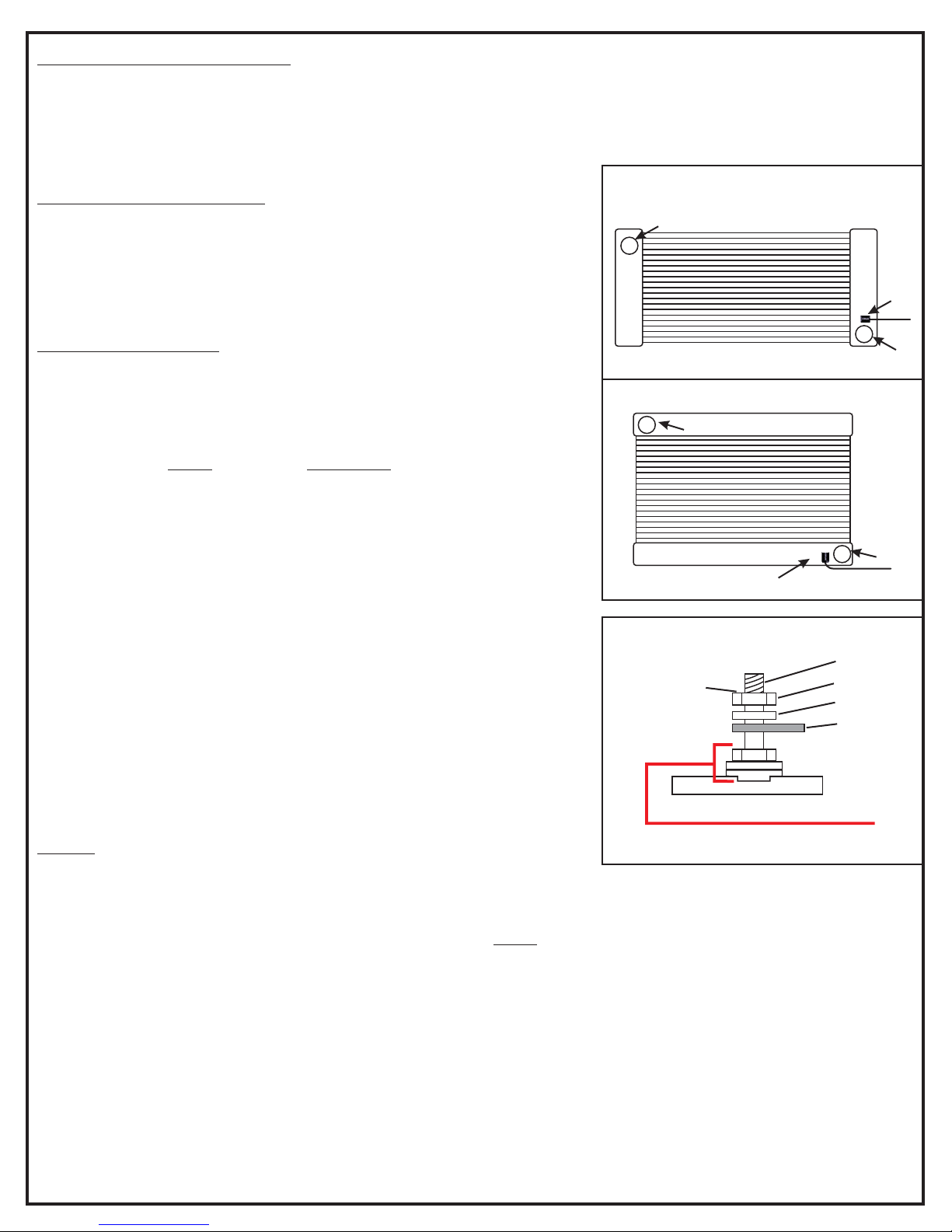
Sensor
Outlet
Inlet
Down-flow radiator
Diagram #1
Cross-flow radiator
Sensor
Inlet
Outlet
Diagram #2
Nut
Split Washer
Ring Terminal
Terminal
Do not exceed
12 inch lbs.
of torque when
tightening
terminal nuts
3. Using four #10 sheet metal screws supplied, secure the unit in place.
CIRCUIT BREAKER MOUNTING
1. Choose a convenient location for the circuit breaker that is between the fan
controller and the battery.
2. Using the circuit breaker as a template, mark and drill two 5/32” holes in the
proper locations.
3. Using the remaining two #10 sheet metal screws supplied, secure the circuit
breaker in place.
SENSOR INSTALLATION
Route the path of your sensor wires to the fan controller before mounting sensor.
If necessary, you can lengthen or shorten sensor wires using an automotive
grade 22-gauge wire.
IMPORTANT: The is designed to monitor the coolant going back infan controller
to the engine, therefore controlling the engine temperature vs. reacting to it. By
design, the sensor install on the of the radiator tank. (SeeMUST COLD SIDE
Diagram #1)
This unit uses 3M double stick tape to adhere right to the radiator tank, therefore
getting a very accurate temperature reading. The surface preparation is critical;
surface must be absolutely free of dirt, oil, peeling paint or any contaminants to
ensure a proper bond.
NOTE: The Ideal application temperature range is 70°F to 100°F (21°C to
38°C).The Minimum suggested application temperature is 50°F (10°C). At 70°F
approximately 50% of ultimate bond strength will be achieved after 20 minutes,
90% after 24 hours and 100% after 72 hours.
1. Once you have determined the location for the sensor, clean & dry the area
with alcohol, making sure there is no left over residue.
2. Remove the red tape backing from the sensor. Attach the sensor to the
desired location applying firm pressure on the sensor for at least 15 seconds.
4. Crimp the red #6 ring connector to the sensor red wire.
5. Crimp the #8 red ring connector to the black sensor wire.
6. Connect red sensor wire to the sensor "+" terminal on the fan controller.
7. Connect black sensor wire to the sensor "-" terminal on the fan controller.
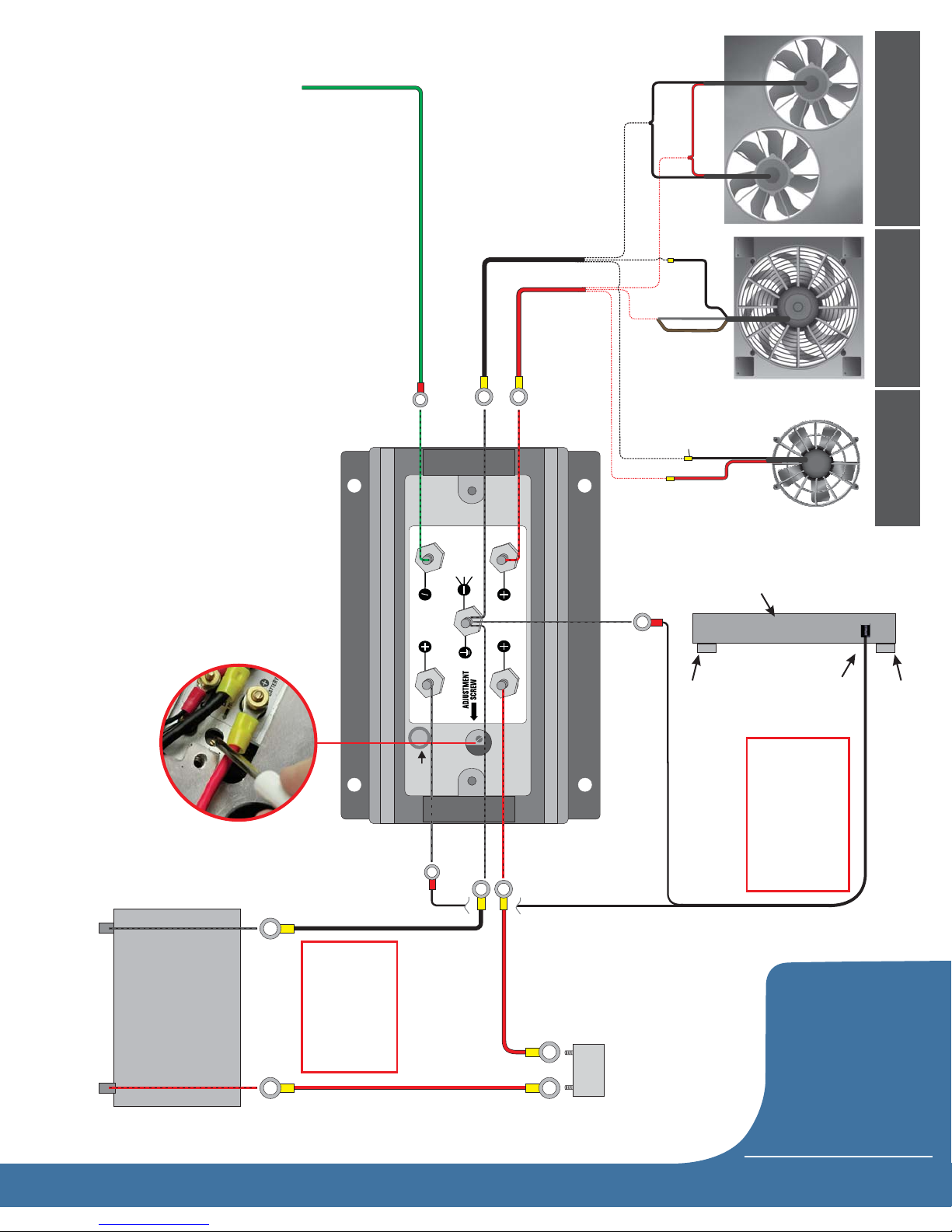
WIRING
(See Quick Reference Guide on page 4)
Before starting, disconnect the negative (-) cable on the vehicles battery.
Using the electrical connectors and wire ties provided, follow the instructions below. (See Dia. #2 for proper lug stacking)
WARNING: The positive and negative wires feeding the controller be connected directly to the vehicles battery.MUST
This is very important because the controller requires a clean signal, do not connect directly to the fuse panel, starter or the
alternator. Improper installation will void the warranty.
1. Using a yellow 5/16” ring terminal & 10 AWG red wire supplied, connect one end of the red wire to the vehicles positive (+)
terminal on the battery.
2. Route the 10 AWG Red Wire now connected to the battery to the circuit breaker previously installed and cut the wire to the
appropriate length.
3. Using a yellow #10 ring terminal, connect the 10 AWG red wire to the “BAT” terminal on the circuit breaker.
4. Using a yellow #10 ring terminal, connect the auxiliary side “AUX” of the circuit breaker to another length of 10 AWG red
wire.
5. Route the red 10 AWG wire now connected to the auxiliary side of the circuit breaker to the positive (+) battery terminal on
the fan controller and connect using a yellow #8 ring terminal.
(2)Page
DO NOT REMOVE!
Preassembled with locking compound
TAMPERING WILL VOID WARRANTY

6. Using the red 10 AWG wire and a yellow #8 ring terminal, connect into the positive (+) fan terminal on the fan controller.
7. Using a yellow butt connector, connect the loose end of the red 10 AWG wire connected to the positive (+) fan terminal to
the positive (+) side of the fan(s).
8. Using a #8 yellow ring terminal, connect the 10 AWG black wire to the negative (-) terminal on the fan controller. Route the
other end of the wire to the negative terminal on the vehicles battery & connect using a 5/16” yellow ring terminal. Do not
connect to a chassis ground.
9. Using a yellow butt connector, connect the 10 AWG black wire to the negative (-) lead of the fan(s). Route the other end of
this wire to the fan (-) terminal of the fan controller & connect using #8 yellow ring terminal.
Green Wire: Override Circuit (Optional)
The green wire is designed to work in two different configurations. When used, this will allow the electric fan(s) to be turned on
regardless of the temperature of the cooling system. The fan speed will quickly ramp up to 60% and will operate between 60
and 100% as temperature increases and decreases. Using a #6 red ring terminal connect the Green wire to the A/C terminal
and select option A or B below.
Note: Use of the Override terminal is optional and not required for the controller to work properly.PWM
A. A/C Override - Using the provided, attach the green wire to a positive (+) 12V output on theblue wire tap connector A/C
compressor.
B. Manual Switch Override - Attach the green wire to the 12V output on the manual switch (not provided).
VEHICLE TESTING
1. Before you start the vehicle, make sure all wires are safely zip tied and away from any moving parts.
2. Start the vehicle.
3. If the manual override function is being used, turn on the A/C or manual switch. Electric fan(s) will ramp up to 60%.
4. Turn off the manual override or A/C function and allow the engine to warm up, fans will ramp up slowly as the vehicle warms up.
TROUBLESHOOTING
In the event the fan controller is not operating properly, perform the following tests:
1. Re-check that all wire splices and connections are secure and crimped properly, making sure wires have no movement
within the crimp.
2. Using a multimeter, verify that the battery terminal on the fan controller has a minimum of 12.6 volts.
Set the multimeter to: DC Volts
Fan controller center ground terminalBlack Lead:
Fan controller positive battery terminalRed Lead:
SYMPTOM: Fan(s) is not turning on when the override function is activated.
TEST: Using a jumper wire, with the vehicle running, connect the battery positive (+) terminal on the fan controller to the A/C
override terminal on the fan controller. This should immediately turn on the fan(s).
Pass: The override is working as designed.
Fail: If the fan(s) do not operate, THERE MUST BE A CONNECTION ISSUE, repeat tests 1 and 2 above. If you still can't get it
to activate, please call our tech team.
SYMPTOM: The fan(s) are working correctly with the override, but will not turn on with temperature.
TEST: Using a jumper wire, connect the sensor positive (+) terminal on the fan controller to the center sensor ground (-)
terminal on the fan controller. This should turn the fan(s) on immediately.
Pass: The fan controller is working as designed.
Fail: Test the sensor (See page 4)
(3)Page
ADJUSTING THE TURN-ON TEMPERATURE
1. Remove the rubber plug from the top of the fan controller
2. Using a 1/8” blade screwdriver, follow the instructions below:
If your engine is running too cool: Turn the adjustment screw CLOCKWISE in increments of 2 FULL turns, then test before
repeating.
If your engine is running too hot: Turn the adjustment screw COUNTER-CLOCKWISE in increments of 2 FULL turns, then
test before repeating.

Please direct all technical questions to our Derale tech line at (323) 266-3850
Warning: Installation of accessories should only be undertaken by those with mechanical knowledge and are familiar with working on
vehicles. Always use eye protection (goggles, safety glasses or shield). Park the vehicle in a well lit area, on level ground and apply the
parking brake. Only work on a cold vehicle that has been sitting overnight, failure to do so will result in severe burns and injury. Before starting
the vehicle, make sure no tools or any other items are left under hood that could interfere with or be drawn into moving parts of the engine.
Failure to follow instructions can lead to severe damage and personal injury.
Derale Performance, Los Angeles, 800.421.6288 www.derale.comCADerale Performance, Los Angeles, 323.266.3850 www.derale.comCA
(4)Page
SENSOR TEST: Disconnect the two sensor wires from the fan controller.
Set the multimeter to: Ohms (200K). If you have an auto select multimeter, please manually set the meter to 200K.
IMPORTANT: This test should only be done after the vehicle has cooled off and has been sitting for a few hours.
Black Lead: Connect to the black sensor wire
Connect to the red sensor wireRed Lead:
A. If the ambient temperature is around 65° F, the meter should read close to 125K ohms
B. If the ambient temperature is around 75° F, the meter should read close to 100K ohms
C. If the ambient temperature is around 85° F, the meter should read close to 80K ohms
D. if the sensor reads 0K Ohms, the sensor is bad and must be replaced, please contact our tech team.
SYMPTOM: Fan(s) are squealing or making a squeaking noise at startup.
TEST: Re-verify that the battery terminal on the fan controller has a minimum of 12.6 volts. See tests 1 and 2 on previous page.
NOTE: If the vehicles battery is located more than 5 feet from the fan controller, the signal could be encountering some
interference or noise, which causes a dirty signal. In some cases an additional electrical filter may be required. Please contact
ADJUSTING THE FAN CONTROLLER TO ITS LOWEST SETPOINT: Remove the rubber plug from the top of the fan
controller and turn the potentiometer screw 25 FULL turns counter-clockwise. This will set your controller to its lowest set point.

Yellow #8
Ring Terminal
Fan(s) (-)
DERALE PERFPORMANCE
SENSOR OVERRIDE
BATTERY
SENSOR
FAN
BATTERY
FAN S
S
( )
AC
U.S. PATENT 7006762 - MADE IN USA
S
( )
( )
Battery
(-)
PWM Fan Controller
Sensor
Wire
Circuit
Breaker
Optional
Override Circuit
12V (+)
(+)
Adjustment
Screw
IMPORTANT
Positive and Negative
wires must be
connected directly to
the vehicles battery
Temperature Adjustment
See instruction sheet for
detailed procedures
Derale Performance
PART # 16795
Customer Service
323-266-3850
U.S. Patent No.
7006762
B
A
T
A
U
X
Calibration
Terminal
Red #6
Ring Terminal
Red #6
Ring Terminal
(Page 4)
Yellow #10
Ring Terminal
Yellow 5/16”
Ring Terminal
Yellow 5/16”
Ring Terminal
Yellow #8
Ring Terminal
Outlet
Sensor
Radiator
tletIn
Sensor must be
installed on the cold
side of the radiator
near outlet
IMPORTANT
Red #8
Ring Terminal
Dual Electric
Fan Setup
Single Two Speed
Electric Fan Setup
Fan(s) (-)
Fan(s) (+)
Fan(s) (-)
Yellow Butt
Connector
Single Electric
Fan Setup
Fan(s) (+)
Gray (+)
Low Speed
Brown (+)
High Speed
Yellow #10
Ring Terminal
Fan(s) (+)
Fan(s) (-)
Q
U
I
C
K
R
E
F
E
R
E
N
C
E
G
U
I
D
E
Table of contents
Popular Controllers manuals by other brands

Asentria
Asentria TeleBoss 830 user manual

Tapeswitch
Tapeswitch PSSW Technical manual

Hunter
Hunter Pro-HC601-A quick start guide

Federal Signal Corporation
Federal Signal Corporation UltraVoice Installation, operation and service manual

Alcor
Alcor AU6981 Series Technical reference manual

Panasonic
Panasonic AKHRP900P - CAMERA CONTROLLER HC Service manual

Orton
Orton AutoFire AF4TS user guide

LEGRAND
LEGRAND Wattstopper LMJA-8125-SM installation instructions

Taconova
Taconova FWCK Installation and operating instructions for manual and remote control options

Emerson
Emerson Fisher S202 instruction manual

PIETRO FIORENTINI
PIETRO FIORENTINI REFLUX 819 Technical manual

JETI model
JETI model SPIN 11 manual