SAI HVAC Compact Comfort VAV12 User manual

1
Copyright. SAI HVAC 2021 V21.1
Compact Comfort by SAI HVAC
VAV12 Controls User Manual

2
Copyright. SAI HVAC 2021 V21.1
Publisher
SAI HVAC
Phone 1300 844 429
Internet www.saihvac.com.au
Revision V21.1
This Technical Manual describes the operation of SAI HVAC VAV12 controls system and air conditioning
maintenance for the end user.
Copyright
This publication is Copyright © 2021 SAI HVAC. All rights reserved. No part of this publication may be
reproduced, stored in any retrieval system or transmitted, in any form or by any means, electronic,
mechanical, photocopying, recording or otherwise, without the prior written permission of SAI HVAC.
Disclaimer
SAI HVAC reserves the right to make changes and improvements to any of the products described in this
document without prior notice. Under no circumstances shall SAI HVAC be responsible for any loss of income
or any special, incidental, consequential or indirect damages howsoever caused.
Warranty
The contents of this document are provided “as is”. Except as required by applicable law, no warranties of any
kind, either express or implied, including, but not limited to, the implied warranties of merchantability and
fitness or a particular purpose, are made in relation to the accuracy, reliability or contents of this document,
SAI HVAC reserves the right to revise this document or withdraw it at any time without prior notice.
Sourcing
Proudly designed and manufactured in Australia by SAI HVAC, an independent Australian-owned company.

3
Copyright. SAI HVAC 2021 V21.1
Contents
1. Connecting your VAV12 system..........................................................................................................................4
1.1 Compatibility ................................................................................................................................................4
1.2 Simple and Upgradable ................................................................................................................................4
1.3 Plug & Play....................................................................................................................................................4
1.4 Html User Interface ......................................................................................................................................4
1.5 Remote Access .............................................................................................................................................4
2. How to connect to your system..........................................................................................................................5
2.1 Direct Connection via Wi-Fi..........................................................................................................................5
2.2 Direct Connection via your LAN ...................................................................................................................6
2.3 Connection via Mothership (Recommended) ..............................................................................................7
2.4 Using the Mothership Cloud Service ............................................................................................................7
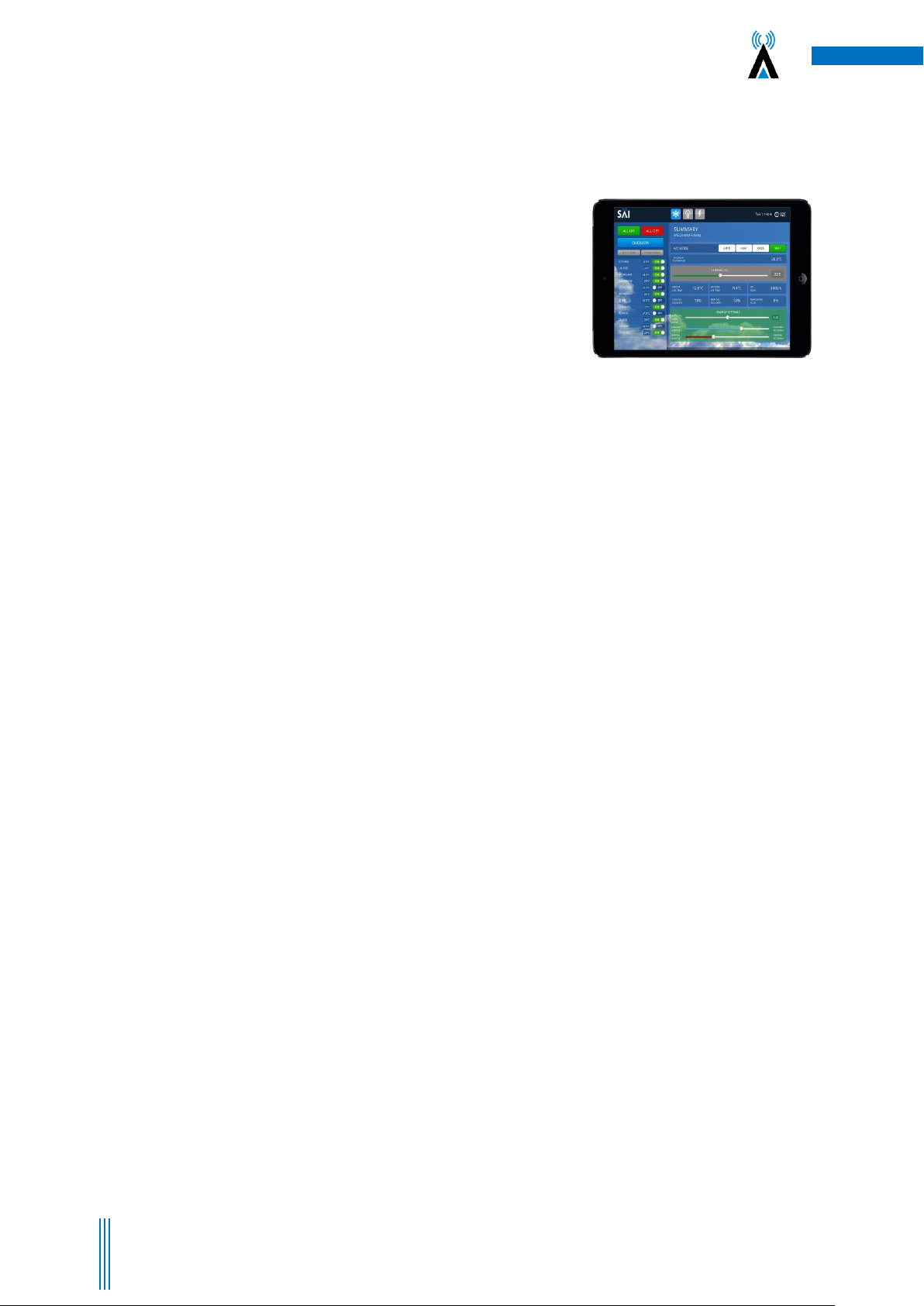
3. VAV12 Operating Instructions Using the User Interface ....................................................................................8
3.1 Changing the System Mode .........................................................................................................................8
3.2 Notes on Dynamic Energy Recovery ............................................................................................................8
3.3 Set the Optional Countdown Timer .............................................................................................................8
3.4 Optional “Cooling” and “Economy” settings................................................................................................8
3.5 Setting the Global Time Schedules...............................................................................................................9
3.6 Leaving Global Time Schedules Page..........................................................................................................10
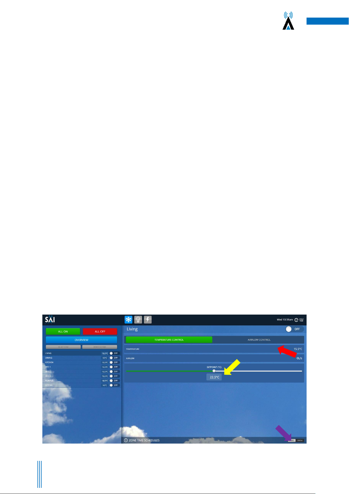
3.7 Accessing Individual Zone ..........................................................................................................................10
3.8 Return to Overview page ...........................................................................................................................10
3.9 Browse to other systems............................................................................................................................10
3.10 Adjusting the settings on a Zone..............................................................................................................10
3.11 Setting Time Schedule for Individual Zones .............................................................................................10
4 SAI HVAC VAV12 Controls..................................................................................................................................11
4.1 SAI HVAC VAV12 Navigator ........................................................................................................................11
4.1.1 Turning the system ON and OFF .........................................................................................................11
4.1.2 Turning a Zone ON and OFF ................................................................................................................11
4.1.3 Browsing to a Zone .............................................................................................................................12
4.1.4 Changing the Temperature in a Zone .................................................................................................12
4.2 Using the Single Button Capacitive Touch Room Controller ......................................................................12
4.3 Surface 7 Touchpad....................................................................................................................................13
5. Manufacturers Recommendations...................................................................................................................14
5.1 Return Air Filter Cleaning.......................................................................................................................14
5.2 Outdoor Unit ............................................................................................................................................14
5.3 Vents & Return Air Grill ..........................................................................................................................14
5.4 Controllers ................................................................................................................................................14
6. Troubleshooting................................................................................................................................................15

4
Copyright. SAI HVAC 2021 V21.1
7. Warranty Key Points. ........................................................................................................................................16
8. Warranty Terms and Conditions.......................................................................................................................16
1. Connecting your VAV12 System
1.1 Compatibility
A User Interface (UI) has been developed to simplify the commissioning, use and change of operating
parameters for the SAI HVAC range of products. A click of “Other Systems” at the top of the user page switches
between the various SAI HVAC systems.
1.2 Simple and Upgradable
The VAV12 architecture allows for remote upgrade of many features so as development continues new
features can be added via an internet connection.
1.3 Plug & Play
You can also add one of the other SAI HVAC systems such as climate control and lighting control. SAI HVAC
systems are “plug and play” you don’t need to call in a programmer, automation specialist or specialist
technician. Once the systems are connected on the same LAN they recognise each other and the appropriate
interface is loaded without the need for you to do anything.
1.4 Html User Interface
The html user interface can be used on most devices with a browser from Smartphone or tablet to PC. The
display results vary slightly depending on your device and browser type used. Many people choose the iPad
mini as their UI platform but a laptop, PC or even your iPhone/Samsung can be used to control your SAI HVAC
product. Now, you’ll likely not use your phone or tablet often to turn lights on and off, after all you have
switches in all the normal places, but when you want to change a time clock setting on your perimeter security
lights or change a group setting, even set multiple dimming levels to create the mood you want for a special
occasion, the User Interface is fast, easy and convenient.
1.5 Remote Access
Providing your system is connected to a Local Area Network (LAN) with an internet connection, System allows
you to remotely access your SAI HVAC systems remotely. This feature can be convenient for many reasons and
is achieved by a secure connection through the SAI HVAC Mothership (MS) global server. You first login to
mothership and then browse to your various SAI HVAC devices connected to your mothership account. Your
mothership account can provide access to your SAI HVAC devices at multiple locations so if you are a building
manager you can have access to all your sites at your fingertips through this one convenient and simple access
point.

5
Copyright. SAI HVAC 2021 V21.1
Figure 1 –Select SAI-VAV network in
Wi-Fi settings
Figure 2 –Enter the password –
“chatterbox”
2. How to Connect to your System
There are three different methods for connecting to your system. The method you choose will depend on your
location and the type of installation you have in your building. Although you can connect to the inbuilt Wi-Fi
(see 2.1) a LAN connection is RECOMMENDED for optimal performance (see 2.2)
2.1 Direct Connection via Wi-Fi
NOTE: The service Wi-Fi is for use when commissioning your system and only when no LAN connection is
available. Some warranty terms are affected when connecting using this Wifi service solution.
Each VAV12 controls system can create its own network via Wi-Fi. This means you can connect your smart
device/computer to the system.
1. Open your Wi-Fi settings on your device and select the SAI VAV network (Figure 1)
2. The Password is “chatterbox”(Figure 2)
3. Once connected to the controls network you can open your browser and browse to the system IP
address 192.168.2.11
4. You may wish to bookmark the page or add a link to your home screen on your device, so that you
can press the link instead of having to refer back to the IP address each time you wish to connect.
(Figure 5)
5. Direct connection requires your personal device/PC to be within range of the controls network. As
this range can vary significantly depending on building conditions, the preferred method of
connection is via a LAN as discussed in the following paragraph.

6
Copyright. SAI HVAC 2021 V21.1
Figure 3 –Logged onto
network
Figure 4 –Type IP address into
browser & add to home screen or
book mark
Figure5 –User Interface launches
2.2 Direct Connection via your LAN
Connecting your system to your local LAN via a network cable connected from your VAV12 MPM module to
your router or a switch connected to your router is the preferred and best method for regular connection. You
can then access your system from anywhere you have LAN coverage. (Figure 6)
When a connection is made your router will assign a unique IP address to the system. You can find this IP by
checking in your router settings but we recommend you download one of the free programs for your apple of
android device such as FING (Figure 7). Such programs search your LAN and list all connected devices. This will
enable you to find your system IP, typically look something like 192.168.1.12 or similar number (Figure 8). By
typing this number into your browser you will be able to access the Opening page of your system.
NOTE: Some routers ship with UPNP disabled. You should check your router instruction manual for details on
how to check this setting. Without UPNP enabled, the system cannot connect. Remember that after power
failure your router may assign a different IP number to your system. In this case you will need to scan your
network with FING or similar program to find the new IP. It is possible to set a fixed IP in your router settings
however the method varies depending on your router brand and model. Your IT specialist should be able to
help. Connecting your system to your router using a cable gives a level of access control as access can only be
achieved by persons or devices having your LAN access password.
Figure 6 –Connecting
via Ethernet cable
Figure 7 –Use FING or similar to
scan network
Figure 8 –User Interface Launches.
Note IP Address is same as listed on
the FING Scan. (bottom of middle
image)
CS-VAV12-MPM

7
Copyright. SAI HVAC 2021 V21.1
2.3 Connection via Mothership (Recommended)
Providing your system is connected to your building LAN and that your LAN has an internet connection, you
can setup an account on the SAI Mothership global server to allow remote connection to your system via MS.
1. Open your browser and browse to https://chatterboxmothership.com.au and click the register
button on the login page. (Figure 9)
2. Fill out your registration details and we will send you your registration name and password within
24 hours together with instructions on how to access your system via the Mothership.
3. If you are within the LAN, i.e. at home and your device is connected to the same network the
system is running on, there will be a link at the bottom of the log in page titled “Your Local Devices”
with the Mac Address and system description. You can click this link to go straight to the User
Interface without having to log in. (Figure 9)
4. Once you have received notice of your User Name and Password, go to the log in page, enter the
details, then press Login.
5. The next screen that launches will have a list of your systems. (Figure 10)
6. To access the User interface for any of your systems press the Launch button on the right hand
side. This will launch the interface and you can start to control your device. (Figure 11)
2.4 Using the Mothership Cloud Service
https://chatterboxmothership.com.au
Figure 9 –Welcome/Login/Registration Page.
Note the links at bottom of page when on the
LAN
Figure 10 –Your devices will be listed on the control centre
screen. Press Launch for the device you wish to interact with.
Log in to the cloud service
Register for the service
Your local devices (on your network (LAN)

8
Copyright. SAI HVAC 2021 V21.1
3. VAV12 Operating Instructions Using the User Interface
1. Open the User interface using the steps mentioned in 2.1, 2.2 or 2.3
2. The page will open in the “Overview Screen”. (Figure 14)
3. The overview screen is where you change all system wide values.
3.1 Changing the System Mode
Press the Auto, Heat, Cool or Vent Buttons. (Figure 14 –Yellow Arrow)
3.2 Notes on Dynamic Energy Recovery
Your SAI HVAC multi zone temperature control system modulates its output capacity to match the heat load. It
continues to cool or heat individual zones until they reach the target temperature (set point). When all zones
are at target temperature, the refrigeration cycle is switched off. On a system where dynamic energy recovery
is disabled, any room can re-activate cooling or heating when the temperature moves away from set point by
0.5°C. Dynamic energy recovery is a technology designed for structures that include a large central area
surrounded by perimeter rooms. The perimeter rooms lose and gain heat at a much faster rate than the
central area. The reason for this phenomenon is that the portion of external walls and roof to room volume is
significantly higher and the additional thermal mass of the central area reduces the rate at which heat is
gained or lost. The dynamic energy recovery algorithm intervenes when a perimeter zone calls for heating or
cooling, it then measures the return air temperature (positioned din the large central zone) to apply a
proprietary algorithm that calculates the flow needed to slow down the rate at which heat is gained or lost.
The slider allows the user to find the right balance for their home or building between energy reduction and
comfort. The slider moves the point at which the worst performing zone can terminate dynamic energy
recovery and force heating or cooling.
The VAV12 zoning control is a unique part of the SAI HVAC system that provides the ability to dramatically
reduce your energy bills. It is important to note that the average household uses 38% of their power bill on
heating and cooling. It is also important to note that every degree Celsius difference between the inside
temperature and the outside temperature adds 10% to the energy cost for that room. SAI HVAC’s multi zone
temperature control system automatically adjusts the airflow to individual rooms to make sure that cooling
and heating overshot is eliminated. There are 3 additional energy settings that are use adjustable that
decrease energy use further. This feature is most often used in combination with occupancy sensors. When
applied in this fashion you can move through your home & the system automatically turns on and off as
required.
3.3 Set the Optional Countdown Timer
Slide the “Auto Off” slider to the desired position between 30 & 240 minutes. The Auto Off timer is only used if
you wish the system to run for that period of time and then switch off. The system then requires a re-start.
This feature is designed as a safe guard for properties where the air conditioning can be left on while not
required. (Figure 14 –Red Arrow). Anytime there is an on event on the system in any zone, the system will
continue to operate. This feature is most often used in combination with occupancy sensors. When applied in
this fashion you can move through your home & the system automatically turns on and off as required.
3.4 Optional “Cooling” and “Economy” settings
See figure 14 (blue arrows), use the slider bar to change.

9
Copyright. SAI HVAC 2021 V21.1
Figure 15 –Global Time schedules page is launched. Set on/off events for the whole system from the Overview page or individual events
can be set from the home page.
brochure.
3.5 Setting the Global Time Schedules
Ensure the “Global Time Schedules” button is “ON” (Figure 14 –Purple Arrow). The Global Time Schedules
button is handy if you are going to be away from the property for a period of time (i.e. holidays). You can
toggle this button to “OFF” and it will not activate your time clock events while you are away. When you return
home, you can simply toggle the button to “ON” and your previously set timeclock events will resume as
before. To access the Global Time Schedules page Press the “HIDE SHOW” show button in the bottom right
hand corner (Figure 14 Green Arrow). This will launch the Global Time Schedules screen (Figure 15).
Setting Global Time Schedules cont… Press on any day in “Schedule A” you wish to activate and the day will
illuminate Green (Figure 15 –Yellow Arrow). Use the drop down bars to set on and off time for the system
(Figure 15 –Red Arrow). Repeat these steps for “Schedule B”. It is important to note that these settings when
launched from the Overview page will activate On/Off events for the whole system (every zone). To set
individual zone timers please see below point 4.11
Figure 14 - User Interface opens in the “OverView Screen”. Set the mode (Yellow Arrow). Set the optional Countdown timer (Red Arrow). Set the Optional
Cooling and Heating Comfort / Economy sliders (Blue Arrows). Turn on the Global Time Schedules button (Purple Arrow). Press the “Hide Show” button to
enter the global time schedules screen (Green Arrow)

10
Copyright. SAI HVAC 2021 V21.1
3.6 Leaving Global Time Schedules Page
Press the “Hide Show” button at the top right of the page and this will take you back in to the Overview
Screen. (Figure 15 –Blue Arrow)
3.7 Accessing Individual Zone
Press on the Select Zone Button. This will drop down a list of the zones in your home or premises (Figure 15 –
Purple Arrow). Then press on the zone name you wish to access and it will launch the User Interface page for
that zone. (Figure 15 - Green Arrow)
3.8 Return to Overview page
Press the overview button.
3.9 Browse to Other Systems
If you have multiple SAI HVAC Air Conditioning or Lighting systems, use the “Other Systems” button to browse
to them. Simply select the system you wish to interact with from the drop down list.
3.10 Adjusting the Settings on a Zone
Use the slider bar to adjust the temperature set point within the zone (Figure 16 –Yellow Arrow). To use the
system most efficiently, we recommend a set point between 20 and 24 degrees for each zone and the zone to
be left in “Temperature Control” mode. To change the mode to “Airflow Control” (disables the temperature
sensor and delivers the maximum airflow specified for the zone at 100%) press on the “Airflow Control” button
(Figure 16 Red Arrow). In Airflow Control mode, you can use the slider bar to adjust the percentage of air being
delivered between 0-100%.
3.11 Setting Time Schedule for Individual Zones
Go to the zone and press the “HIDE SHOW” button in the bottom right hand corner (Figure 16 –Orange
Arrow). Then follow the same instructions as per points 4.5 and 4.6. Setting zone schedules will only action the
event in the zone you have selected.
Figure 16 –Adjust the Set point using the slider bar (Yellow Arrow). You can use the optional Airflow control feature by pressing the “Airflow Control
button (Red Arrow) and adjusting the slider bar. To set time clock events in each zone, select the zone and then press the HIDE SHOW” button (Purple
Arrow), then follow the time schedule instructions in points 4.5 & 4.6.

11
Copyright. SAI HVAC 2021 V21.1
4 SAI HVAC VAV12 Controls
4.1 SAI HVAC VAV12 Navigator
4.1.1 Turning the System ON and OFF
Press the ON/OFF Button when on the main screen to turn all zones ON or OFF.
4.1.2 Turning a Zone ON and OFF
Press the ON/OFF Button when in the zone screen to turn an individual zone ON or OFF.
Set Button
Navigate Left
Navigate Right
Current Mode
Current Temperature
Navigate Up
On/Off
Navigate Down
Temperature Set Point

12
Copyright. SAI HVAC 2021 V21.1
4.1.3 Browsing to a Zone
Use the left and right arrow buttons to scroll through available zones on your system. Continually scrolling in
one direction will cycle the main screen and available zones
4.1.4 Changing the Temperature in a Zone
Once you are on the zone page you wish to adjust, use the UP arrows to adjust the temperature up and the
DOWN arrow to adjust the temperature down.
4.2 Using the Single Button Capacitive Touch Room Controller
The Single button room controller is an easy to use on / off controller for your room or zone. It has a built in
temperature sensor with a central button for turning a zone on or off. If the zone is switched off, the LED
indicator around the capacitive touch button will be turned off. Otherwise the LED indicator has three
different colours that signify different operations:
a) Green –Indicates the zone is active, but it is not currently needed as the room is at temperature.
b) Blue –indicates the zone is active and running on cooling.
c) Red –Indicates the zone is active and running on heating.

13
Copyright. SAI HVAC 2021 V21.1
4.3 Surface 7 Touchpad
Capacitive Touch Buttons
Page Navigation

14
Copyright. SAI HVAC 2021 V21.1
The air conditioning plant and control system contains no user serviceable parts. Installation, service
and maintenance of these components should be carried out by a suitably qualified technician
5. Manufacturers Recommendations
Regular maintenance will ensure your SAI HVAC system operates at maximum efficiency.
5.1 Return Air Filter Cleaning
Cleaning the filter in the return air grille is recommended every month. Filters may be cleaned by either
vacuum or hand wash in mild detergent. Never operate the air conditioner without the filter. Ensure the filter
is in good condition, if not contact your installer for a replacement filter (a charge will apply).
5.2 Outdoor Unit
Do not place any object in front of the condenser. Keep free of grass, leaves and any other form of debris. This
will allow for proper air flow and ensure unit efficiency.
5.3 Vents & Return Air Grill
Regular cleaning of the return air grill and air vents is recommended. This will prevent build-up of dust and
dirt.
5.4 Controllers
Clean the wall controllers with a dry cloth. Do not use a spray detergent or water.
IMPORTANT: Neon signage will interfere with the operation of SAI HVAC controllers. Do not have neon lights
near SAI HVAC Navigators or Room controllers as the Electromagnetic field (EMF) will disrupt the operation of
the controllers.
The control circuits for the indoor and outdoor units carry voltages > 240 VAC which can cause serious injury or
death.

15
Copyright. SAI HVAC 2021 V21.1
6. Troubleshooting
Problem
Possible Solution
Air Conditioner has restarted but does not operate
for 4 minutes
The normal operating behaviour to protect the
compressor. Wait until the air conditioner begins
operating.
Operation stops for up to 12 minutes during heating
and a different noise/sound comes from the unit.
The unit has entered defrost mode to melt the frost
which has accumulated on the outdoor unit. This
will take no longer than about 12 minutes so wait
for the unit to resume normal operation. (Frost
accumulates on the outdoor unit when the outdoor
temperature is low and the humidity is high. Water
comes out from the outdoor unit).
The air conditioner does not operate.
Has the mode been set correctly?
Is at least one zone ON.
Has the setpoint for ON zones been set low enough
for cooling or high enough for heating?
Has the circuit breaker been tripped?
The air conditioner does not cool/heat effectively.
Has the mode been set correctly?
Are all the windows and doors closed?
Are the filters dirty?
Are the intake or outlet vents of the outdoor unit
obstructed?
The outside temperature maybe below or above
design conditions. Turning OFF any zones not
required may help.
Abnormal noise is heard during operation (except
during the defrosting operation).
Water leaks from the indoor unit.
Switches or buttons do not operate properly.
Fault code is displayed on the controller.
Contact your installer. Your model and serial
number is recorded on the inside of the last page of
this booklet.

16
Copyright. SAI HVAC 2021 V21.1
7. Warranty Key Points.
SAI HVAC systems used in human comfort applications are covered by a parts and labour on-site warranty as explained in
detail later in this document. SAI HVAC is committed to making sure that our clients get years of trouble free operation
from what we believe to be the world’s best residential concealed ducted air conditioning system. Like all warranty policies
the SAI HVAC HVAC warranty provides peace of mind for clients and details the rights and responsibilities of SAI HVAC and
the client.
HVAC systems like all machines require regular maintenance. If regular maintenance is not completed the system
operation is compromised and although SAI HVAC systems have many safety systems built into their operation system
longevity will be compromised. In most residential environments a single service per year completed in accordance with
the programmed maintenance schedule is sufficient to ensure that system performance is not compromised, and warranty
terms and conditions are met.
SAI HVAC tracks all activity relating to your system and all other systems no matter where they are installed. This allows us
to make sure that all performance information is passed directly back to our Engineering Team so that Future SAI HVAC
systems can continue to set a new standard in product reliability. Tracking all system activity also helps our Service Team
identify any environmental factors, unusual activity or a repeat faults. To achieve the required level of tracking to provide
peace of mind for our clients we require that all systems are registered on the SAI HVAC website within the first twelve
months of operation. Immediately on completion of the online registration form a unique identifier will be sent to the
nominated email address, your system warranty will be extended from twelve months to six years from date of
manufacture or five years from date of installation (whichever expires first).
SAI HVAC has developed a diagnostic system that dramatically reduces the need for access and by doing so reduces risk to
the health of technicians, reduces risk of property damage, reduces disruption to your work, family or social life and
reduces the overall cost of warranty and support cover for the life of the system. SAI HVAC Ambient Intelligence Pty. Ltd.
have calculated the cost of warranty on this basis and require that each SAI system is connected to a network and has
internet access. If you plan on installing a system that does not have network and internet access, please contact SAI to
better understand the impact on warranty cover.
1. Register your system: https://www.saihvac.com.au/register-your-system
2. Keep your system well maintained (If a fault occurs due to lack of maintenance or would have been rectified sooner if
noted during programmed maintenance your claim may be declined or reduced).
3. Be mindful of possible travel charges (is there an appointed service agent within 100km from your home?).
4. Be mindful of broader system components that are not manufactured by SAI HVAC and may have different warranty
terms and conditions (This may include iPads, motorised dampers, three phase soft start modules, ductwork, diffusers, and
grilles).
5. Be mindful that in the rare event that a failure occurs the replacement component is covered by twelve months or the
remaining term of the system wide warranty whichever is the longest.
8. Warranty Terms and Conditions
Please visit www.saihvac.com.au to view SAI HVAC terms and conditions in full.
System Registration
Registration No. ………………………………………………………. Date Issued. ………………………………………………………………….
SAI HVAC
Phone: 1300 844 429
Web: www.saihvac.com.au
Email: service@saihvac.com.au
Other manuals for Compact Comfort VAV12
1
Table of contents
Popular Controllers manuals by other brands

SMC Networks
SMC Networks LEKFS G Series instruction manual

Beninca
Beninca YAK 25 OTI manual

Generac Power Systems
Generac Power Systems PWRmanager owner's manual

DPS Telecom
DPS Telecom NetGuardian 420 DNP3 Hardware user manual

Ultra Products
Ultra Products Fan Commander ULT31810 Specifications

suntouch
suntouch PM-653 Quick setup guide