Desert Aircraft DA85 User manual

O
Ow
wn
ne
er
r’
’s
sM
Ma
an
nu
ua
al
l
7-
07

Safety Instructions
WARNING!
This motor can cause severe harm to you, and/or others, if misused or if
these safety precautions and instructions are not observed. Desert Aircraft is not
respons
ible for any loss, injury or damage resulting from the miss
-
use of
this product.
You alone are responsible for the safe operation of your motor.
Do not operate the motor if you do not want to be completely responsible for any damage or injury
incurred or
caused during its
operation.
Read all instructions before operating your motor.
If you have any questions about any aspect of operating this motor, do not attempt to start or
operate it.
Never operate the motor, or fly, alone.
When operating the motor,
never stand, or allow anyone else to stand, in front of, or to the side of
the propeller. Always stand behind the propeller.
Keep away from the prop while operating the motor. Do not wear loose clothing near the motor or
prop. Do not run the motor near l
oose material such as dirt, gravel, power cords, ropes, sand, etc.
Loose material can be drawn into the turning prop causing injury or damage.
Always operate the motor in an open area. Do not operate indoors.
This motor can develop tremendous thrust. Make sure the aircraft is properly secured when starting
or operating the motor.
This motor can stop at any time, for a variety of reasons. Do not fly your plane in a way that damage
or harm will result if the motor stops running.
Inspect motor mount bolts a
nd firewall integrity before operating the motor.
Anyone in the immediate area of the motor should use eye protection during operation of the motor.
Keep spectators at least 30 feet away when operating the motor.
Turn off the motor before making any adjust
ments.
Always use the proper size propeller. Never use a damaged, modified
,
or repaired propeller.
Always use the correct length propeller bolts. Do not use spacers behind the propeller.
Spinner cones must not touch the propeller.
Thin
ner props may r
equ
ire using shorter prop bolts, especially if not using
a spinner back plate.
M
ake sure your prop bolts do not bottom out in the propeller hub.
Check that the propeller bolts are tight before every flight.
Always install an ignition kill switch to stop the
motor.
Adjust the carburetor linkage so that the motor will stop when the carburetor is completely closed.
Gasoline is extremely flammable. Be careful of any sparks from electrical contacts such as fuel
pumps, battery chargers, etc. Do not allow smoking
in the area of your fuel supply or motor. Store
fuel in approved containers and in well ventilated areas.
Allow the motor to cool before touching or fueling.
Always turn the prop a few revolutions after running the motor to discharge the ignition system.
The ignition system develops extremely high voltage. Do not touch it during operation.
1
Mounting the Engine
The DA85
features a rear induction carburetor tha
t is intended to protrude or breath
e
through the fire wall.
While mounting and initial setup of the engine and with the carb through the firewall can take some extra
work, t
his carburetor location provides a stable air environment for consistent high perf
ormance, while
greatly reducing
carburetor noise
.
If the firewall/motor box is to far back, it can be extended using by adding a layer or layers of
aircraft plywood, or extending the motor box with aircraft plywood.
We do not recommend using standoffs o
r spacers to mount the DA85.
Vibration and stress to
the engine case increase when standoffs are used. Damage from using standoffs or spacers will
not be covered under warranty.
If you still elect to use
shims or spacers between the rear of the engine and
the firewall
, make
sure that the
mounting faces of all the spacers or shims
are flush
with the rear of the engine
. If
the
face of all spacers
are not in the same plane
or
perfectly flush with the rear mounting face of
the motor, the crankcase
may be
damag
ed.
Again, this will not be covered under warranty.
Make sure the carburetor has adequate clearance near the inlet to allow an unobstructe
d airflow
into the carburetor. If the carburetor is located in front of
a former or firewall,
be sure there is at
lea
st
1” (25mm) of clearance from the carburetor inlet. If
there is less than 1” clearance,
make a
hole larger than the carburetor inlet diameter in the
former or
firewall.
The throttle arm is tapped for a 2
-
56 SA
E ball link.
If you wish, the
throttle
return
spring can be
released
or cut on one end, but
not removed
.
Without the spring,
vibration will wear and damage
the shaft and carb plate
. This wear/damage will allow air and fuel to enter the engine when in the
closed position
, resulting in an unreliable id
le and
er
ratic throttle control
.
The choke lever can be actuated
by
hand with a small light weight pus
hrod
or by a small servo
behind the firewall. There are two arms on the choke shaft. One is re
-
moveable and can be
repositioned to give proper geom
etry fo
r
linkage access from the bottom or rear.
Do not remove
the detent ball and spring on the choke shaft.
We do not recommend soft mounting the engine as it can cause
problems with exhaust systems
and carburetor linkages.
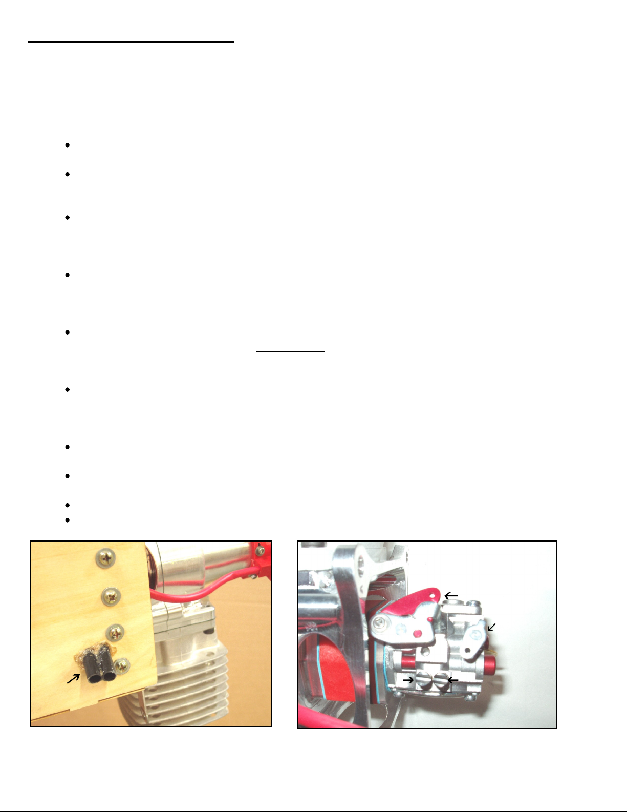
If the carb
ure
tor is enclosed, guide
tubes
pointed directly at each needle
can be installed to
allow easy needle adjustments with a narrow screw driver. (
See photo
)
Make sure firewall and/or motor box are secure.
Check the mounting bolts regularly to insure they are tight.
Throttle arm
C
hoke arm
s on b
oth sides
L
H
Needle valve adjustment
guide tubes
2

Ignition System
When making electrical connections to the ignition system, use the same gauge wire (or larger
)
as
used on the red and black power leads on the ignition module, all the way to the battery pack.
Keep wire lengths to a minimum. Please use the heavy
-
duty connector plugs supplied with the
ignition or something similar.
Use
a high quality switch such as a Futaba or JR heavy
-
duty switch.
Small
size R/C receiver
switches are not recommended.
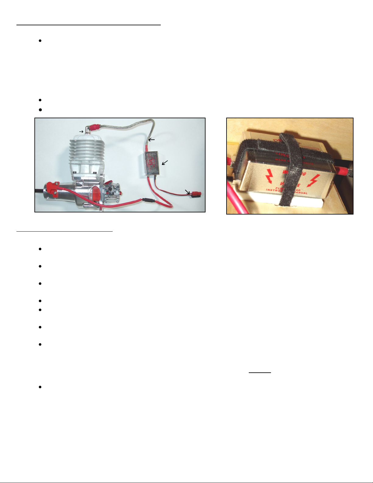
The ignition module must be soft mounted to prevent vibration damage.
DO NOT HARD
MOUNT OR USE DOUBLE SIDED TAPE!
Zip ties can also be to
o firm.
We recommend Velcro
fabric
s
traps (
T
he sew on type material). Slots are cut in the motor box, bulkhead, or mounting
plate
allowing the Ve
l
cro strapping to be threaded through and then wrapped around the
module.
Place a piece of high density foam
rubber between the ignition and the mounting
surface.
If Zip tie
s
are going to be used, wrap the module in foam rubber first.
Isolate the charge circuit from the ignition while charging the batteries. In other words, don’t
“charge” the ignition module
while charging the battery.
Most receiver switches do this
automatically
.
Use 4.8
volt 4 cell,
or 6.0 volt
5 cell battery pack
s only.
(We see
no
significant difference in
engine performance between the two.)
While the ignition
unit is rated for 4.8 to 6 vo
lt packs
, it
will handle
the
higher voltage they actually produce, including the high “peak” voltage right after
charging.
Higher voltage
batteries
will damage the ignition system and will void the warranty.
We recommend a 1500 mAh or larger pack. With t
his size pack, the ignition pack should
typically
last longer tha
n your receiver pack will. If a standard no load
meter shows 5.0 volts or
less, don’t fly. Re
-
charge.
Use a 5.2 to 6.0 volt regulator on pack
s
rated above 6.0 volts.
When connecting the red
pick
-
up sensor to the ignition module, make sure that the
polarity of the wires entering the connectors is correct (Brown to brown, orange to
orange)
Unlike some ignitions, the Desert Aircraft ignition is designed to spark only when the prop is
flipped at
a high speed. If the prop is not turned over at “starting” speed, the ignition will not fire.
This helps to prevent the motor from firing accidentally. Unless you are having problems starting
the motor,
we
don’t
recommend
“testing” the ignition with t
he plug removed from the cylinder.
Do not operate the ignition without a spark plug properly installed in the cap! Doing so
will damage the ignition!
W
hen removing the spark plug cap
, PULL STRAIGHT out on the cap,
not the shielded ignition
wire!
Do not us
e pliers to grip the plug cap! If the cap seems loose, and is not making a solid
metal-
to
-metal contact with the spark plug base, contact Desert Aircraft for a replacement.
To
prevent radio interference, the spark plug caps must have the split retainer ri
ng around their
base
–
DON’T FLY WITHOUT THEM!
Protect t
he shielded plug wire
from rubbing against fiberglass
or sharp edge
s
of wood or
metal!
Rubber grommets and plastic “spiral wrap” insulation from automotive or electronic
supply stores work well
to pr
otect your braided shielding
. Holes in the braided shielding can
emit R/F noise (i.e: RADIO INTERFERENCE!) Damaged plug wires are not replaceable and
may require the ignition to be replaced!
Protect them!
Keep ignition components and wiring separated as
much as possible from your receiver,
receiver battery, servos, wiring and switches.
Don’t use metal
-
to
-
metal l
inkages to operate the throttle or choke.
Timing is set at the factory and should not need adjustment. Contact Desert Aircraft if you have
any qu
estions regarding timing.
Only use
NGK CM-6
spark plugs. Other plugs may not fit the plug caps firmly and cause poor
running or radio interference.
3
Ignition System
(Cont’d)
Always per
form a radio range check before flying.
Range
check the radio system according
to the radio manufacturer’s guidelines
with the
engine off, then with the engine running. The
operational radio range should be nearly the same.
If there are “glitches”, DON’T FLY!
Check for holes in the braided shielding or lo
ose connections (spark plug cap to spark plug
,
all
connectors, and switches). If that doesn’t solve the problem, re-
locate your ignition and receiver
components farther apart. If the problem persists,
return the ignition to Desert Aircraft for
inspection.
If your radio has a failsafe, program the throttle to close in Failsafe mode.
Plug gap is .018” to .020” (.45mm to .50mm)
Soft mount ignition module
Plug cap
S
hiel
ded plug wire
Velcro
Module
Timing sensor
Connector to switch and battery
Foam
Sensor c
onnector
Fuel and Oil Mix
Low octane
pump
gas
oline
is recommended. High
er
octane gasoline can actually lower
performance unless a
tuned exhaust system
is used.
We recommend purchasing your fuel from “
name
brand” gas stations. We have seen problems
with
cheaper
gas from some discount type outlets.
We recommend filtering your fuel between your fuel container and your plane’s fuel tank.
A high
flow filter, or clunk/
filter, between the tank and motor is also a good idea.
Make sure the plane’s tank is well vented and the fuel clunk moves
freely.
Use of any other fuel or additives such as
nitro formulas, aviation gas, white gas, etc.,
can harm the motor and void the war
ranty.
Do not use any silicon sealers on the fuel system. Gas can break it down and carry it into the
carburetor.
For Break
-
in
, we recommend a petroleum
-
based oil such as Lawn Boy
Ashless
or Pennzoil Air
Cooled 2 stroke oil at 32:1 ratio. Run at least 2
to 4 gallons of petroleum oil/gas mix for break
-
in.
This allows the ring
to seat quickly without blow by.
Use a pr
op that allows peak RPM
over
6,2
00
d
uring the break
-
in process.
The High needle can be s
et
just
slightly
rich during break
-
in.
Too
rich will
cause problems with excess
residue and
carbon
build up.
After the break
-
in process,
we recommend a high quality synthetic oil. As for brand of oil,
there are many good ones on the market. Some oils, and their mix ratios, that Desert Aircraft
recommends
are: Amsoil Saber Professional (100 to 1),
Red
-line Two Stroke Racing Oil (40 to
1)
, Bel
-
Ray H1
-
R (50 to 1).
Mobil
MX2T (32 to 1) These oils can be found at most motorcycle
shops.
4

Recommended Props
Always tighten prop bolts and inspect your prop and spinner before each flight!
A
void large/heavy load props during the break
-
in period.
Regardless of siz
e or brand, it is important
to not overload the engine during break-
in. Check the rpm on the first run
and make sure it is
around
6,200 rpm
or higher
. B
e
more concerned about overloading the engine than over revving it.
The optimum prop for your aircraft w
ill depend on exhaust type, airframe weight, airframe size/drag,
altitude, and your flying style.
After break
-in, we have found the optimum static RPM range for good
performance is 6,000
to 6,700 depending on prop and exhaust selection.
Some recommend
ed
break
-
in props are:
Menz 26x10, Mejzlik
26x10, Mejzlik
27x10TH, 24x10 Mejzlik 3 blade
Some recommended props after break
-i
n are all of the above as well as
:
26x12 Mejzlik, 26x12 Menz, 26x10 Xoar,
25x12 AirModels 3 blade
.
If a tuned pip
e system is used, all props listed above can be used along with:
27x10 Mejzlik, 27x10 Menz,
27x10, Xoar,
28x10 Mejzlik
, 24x12 Mejzlik 3 blade, 24x12W Mejzlik
3 blade.
Lower rpm normally equals less prop and engine noise, but less power.
A 3
blade prop just over
6,000 RPM can be very quiet.
Smaller diameter props (less tip speed) and more pitch (more
load/less rpm) will reduce noise. 3 blade props normally have less diameter and more load from the
pitch and extra blade. This normally makes the
m the quietest props.
2 blade prop
s
above 6,
4
00 rpm will develop a lot of power.
You may find that you prefer the higher
revving break
-in size props, even after break-
in.
A general rule of thumb
for good flight performance
is the larger and/or heavier t
he plane, the lighter
the prop load to allow the engine to create more horse power. On a lighter/smaller/cleaner airframe
horsepower requirements are not as critical
. Y
ou may enjoy the benefits of a larger prop disc
for
better down line braking, torque rol
ling, etc.
Always use a drill guide to drill your props.
We normally drill from the back side, then again from the
front to insure the screws don’t bind in the holes.
Always check the balance of your prop.
For safety, we recommend painting the tips of y
ou props (front and back) with a bright color,
especially black props.
Never use a damaged or repaired prop, or a prop that has struck the ground or any other object.
Damage that can be hard to see could turn into disaster when turning at thousands of RP
M.
5

Starting
Avoid
running the engine without the wings installed on the fuselage. Without the mass of the
wings, vibration will be very pronounced.
Check that prop bolts are tight and spinner is secure.
Mak
e sure the starting area is free of dirt, sand, gavel, or other loose debris
Always wear a heavy leather glove when starting the engine.
Turn on the radio system and check the throttle operation and position.
Have someone (with eye protection) firmly hold
the plane.
1.
Close the choke completely.
2.
Open the throttle to approximately 1/8 position.
3.
Turn on the ignition.
ALWAYS BE PREPARED FOR THE ENGINE TO START ON ANY FLIP OF
THE PROP, whether the ignition switch is on or off! Flipping the prop with the ignit
ion off may flood
the engine.
4.
Give the prop a quick, firm, flip counter clockwise. Follow through quickly as you flip the prop so
your hand swings out of the props path. Repeat until the engine fires or “pops”.
Flip the prop
one
more time.
5.
Open the chok
e.
6.
Set throttle to idle position. (carburetor butterfly plate
just
slightly open)
7.
Flip the prop again until the engine
fires and
runs.
8.
Let the engine warm up for 15 to 20 seconds before advancing the throttle.
Th
e engine may not need to be cho
ked
if the
engine is re
-started shortly after the previous run.
If the engine becomes flooded, removing or “pinching
”
the fuel line
while flipping the prop quickly will
help to dry things out. The spark plug can also be removed to speed the process.
Needle Adjustme
nts
The needle farthest
to the rear of
the engine is the “High End” needle. The needle closest to the
engine is the “Low End” needle. Turning the needles clockwise “leans” the fuel mixture. Turning
the needles counter
-
clockwise “richens” the fuel mixtu
re.
Settings will vary with altitude, temperature, humidity, fuel, carburetor variances, etc. A general
starting point is:
1-1/2
open on the
L
ow needle,
1-1/2
open on the
H
igh needle.
Adjust the High needle to peak rpm. A tachometer is a great help, but
remember that the
peak
RPM
usually
drop
s
a little bit after every start due to heat build up. Don’t lean the mixture any more
than necessary. If the rpm steadily drops at full throttle or fades on long vertical maneuvers, the
engine is too lean and is ov
er heating.
Adjust the Low needle until you achieve a smooth idle and a reliable transition to high throttle.
Generally if the engine “stutters” or “coughs” in the mid range or when the throttle is advanced, the
Low end is too rich and possibly even the High needle. If the engine dies quickly
or sags during
transition
, the Low end is probably lean.
Note: The low needle flows a small amount of fuel through
the entire RPM range. Adjusting the low needle can have a slight effect on the higher RPM range.
Wh
ile it is possible for the DA85 to idle below 1,000 RPM, an idle setting around 1,500 RPM insures
a more reliable idle and throttle transition. Prop size has a big effect on the idle characteristics.
Set the High needle
only
slightly rich during break
-
in.
Operating the engine overly rich
not only
reduces power, it creates other problems such as poor transition, pre-
mature carbon build
-
up,
fouled plugs, excessive exhaust residue, sticking rings, and overall rough running.
6

Trouble Shooting
Motor w
on’t start
:
Possibly flooded:
The DA
85
normally only needs to be choked for the first start of the day. Over
choking can cause flooding.
Check battery voltage (should be at least 5.0
+ volts) and all ignition connections, wiring, and
switches.
Check for breaks near all connectors, crimp joints or solder joints.
Voltage regulators can fail intermittently or totally. If using a voltage regulator
, try
testing with a 4 or
5 cell pack witho
ut the
regulator
.
Check tank venting, clunk position, and fuel flow.
Check all fuel lines for kinks, pin holes,
or damage.
Does fuel move toward the carburetor when the prop is flipped?
If fuel isn’t moving towards the carburetor, is the choke plate comple
tely closing? Is the carburetor
or carburetor mount loose causing an air leak? Look for fuel
seepage around the carburetor
mounting area.
Is the throttle set at idle or slightly higher after engine “pops”
and choke is opened?
Make sure prop is flipped over with authority. The ignition won’t fire at low speed.
If a lot of fuel drips from the carburetor, the engine may be flooded. If so, remove and dry
spark
plug
, or replace it
. Try starting again without using the choke
.
Motor runs poorly
or stops
:
R
ough running can be an indication that t
he engine might be too rich. Make sure both
needle
s
are adjusted to peak performance. Due to changes in air pressure and air flow in
the cowl when the plane is flying, the needles may need to be adjusted to deal wi
th
in flight
performance, not just the way the engine runs on the ground.
This may take several ground
adjustments and flight tests.
Make sure carburetor has not come loose causing an air leak in the carburetor mounting
area. Look for fuel seepage.
If you
r radio has a Battery Failsafe option
, the throttle can stop working momentarily when
the receiver battery voltage drops.
Check that the fuel clunk is intact and can move freely to the correct tank position.
Check all ignition connections and switches care
fully. Faulty switches and contacts can
cause momentary loss of ignition power due to vibration and harness movement during flight.
Check Ignition battery voltage.
If the engine
runs poorly and the
RPM tops out at
3,000 to 4,000 RPM
, make
sure that the
po
larity of the wires entering the connectors is correct (Brown to brown, orange to orange)
.
The connectors can be forced together the wrong way.
Make sure
your
fuel is fresh. Changes in atmospheric cond
itions can cause water
condensation in gas cans and ta
nks. Look for water in your fuel can and plane’s fuel tank.
Needle settings may need adjustment when the engine is moved from one plane to another
or cowl configurations
are
changed.
This is because even slight changes in air flow can
change the tuning of
the carburetor.
Make sure the choke stays open during flight. Vibration and a heavy unsecured choke
linkage can cause the choke to close under high G
-
loads.
7

Maintenance
Being a high performance 2 stroke engine, certain parts can wear quickly. Under normal operation,
pistons, piston rings, needle bearings, spark plugs, etc. may need occasional non
-
warranty
replacement to insure peak p
erformance.
Screws can come loose!
After a few flights check that all screws are secure.
Periodically check
that
all screws are tighten
ed t
o the correct torque rating.
Size
Torque spe
cifications
Spark plug:
CM
-
6, 10mm 90 in. lbs.
Steel p
rop bolts:
M5x 50mm
65 in. lbs.
/
wood props, 80 in. lbs.
/
carbon props.
Steel c
rankcase bolt
s:
M5x
16
mm
130 in. lbs.
Steel c
ylinder base bolts:
M5x
16
mm
160 in. lbs.
Alum. alloy c
arb mount bolts:
M5x
75mm
6 in. lbs.
*
*Caution
:
Care must be taken to not over tighten the
carb mounting
bolts. Over tig
htening can
distort and damage the injected molded reed valve parts and rubber gaskets.
Use a 4m hex wrench for all M5 screws.
For spinner mounting, the crankshaft extension is threaded for M5 screws. In this application (steel
to steel) the 10
-
32 SAE screws supplied with most spinners will work fine in the M5 threaded hole.
Do not substitute 10
-
32 screws for any other screws on the engine!
Inspect the engine periodic
al
ly for any signs of fuel seepage. This can indicate an air l
eak which can
create a lean fuel/
air ratio, which in turn can caus
e er
ratic running and engine damage.
If tightening
the appropriate screws does not cure the problem, contact Desert Aircraft.
After prolonged use, carbon deposits can build up on top of the
piston and on the combustion dome
of the cylinder. Great care must be taken when trying to remove these carbon deposits to avoid
damaging the parts. Once an attempt is made to remove carbon has been made, the task must be
completed, as any remaining carbo
n may be loosened and can dislodge while the engine is
running. This can damage the engine and/or bridge the spark plug.
Manuals may be updated with additional tips and trouble shooting info from time to time
. Please
check our web site for downloadable m
anuals and
updates.
IF ANY PROBLEM PERSISTS, PLEASE CONTACT
DESERT AIRCRAFT FIRST!
We designed and manufactured your engine and have serviced and trouble shooted thousands more. We
cover your engine’s warranty, not someone at the field or a stranger on t
he Internet. Please give us the
opportunity to help!
8

DA85 WARRANTY
Your DA85
engine and ignition system are covered with a 2 year warranty by Desert
Aircraft, starting from
the date of purchase.
This warranty covers defects in workmanship and materials only.
Being a high
performance 2 stroke engine, certain parts can wear quickly. Under normal operation,
pistons, piston rings, needle bearings, spark plugs, etc. may need occa
sional non
-
warranty replacement to insure peak performance.
Do not disassemble the engine or ignition system
. Disassembly of th
e engine or
ignition system can
void the warranty on that item.
Any modifications to the engine, or the ignition system, other than those authorized by
Desert Aircraft, will void this warranty.
This warranty does not cover the following:
Normal wear of any parts.
Damage caused by improper handling, operation, modifications, or maintenance.
Damage caused by a crash.
Damage caused b
y using improper fuel or additives.
Damage incurred during transit to Desert Aircraft (pack carefully!)
Shipping expenses to and from Desert Aircraft for warranty service.
DESERT AIRCRAFT WILL NOT SHIP ANY
WARRANTY
REPLACEMENT
ITEMS
UNTIL DEFECTIVE ITEMS
IN QUESTION ARE RECEIVED BY
DESERT AIRCRAFT
Please be sure to pack any items sent us carefully
to prevent any shipping damage
.
Enclose the item(s) in a plastic bag(s) and then wrap with protective bubble wrap. Bagged
parts, ignitions, etc, can be taped
to larger items so they don’t get “lost” in the packing
material. Use a box with ample room.
Be sure to include your contact information as well as
a description of the problem.
Desert Aircraft
1815 S. Research Loop
Tucson, AZ 85710
Ph 520 722 0607
Fax
520 722 5622
Email
Web
www.desertaircraft.com
Office hours are 9 am to 5 pm Arizona time.
9

Repair/Return For
m
Please make copy
P
lease fill out and enclose this form when shipping items for service
Customer Name_________________________________ Date___________
Address________________________________________________________
City______________________ State______ Zip_________ Co
untry________
Phone #_________________ Cell #__________________
Email _________________________
Items in Box:
DA
50 Serial #
__________ DA8
5 Serial #__________DA100 Serial #__________
DA
150
Serial
#__________
Single
Ignition
Serial # ________
Twin
Ignition S
erial # ________
Prop Bolts? __________
Prop washer? ________
Muffler(s)? ___________
Standoffs? ____________
Other Items? __________
REASON FOR RETURN? ___________________________________________________
________________________________________________________________________
________________________________________________________________________
________________________________________________________________________
______________________________________________________________
__________
________________________________________________________________________
________________________________________________________________________
________________________________________________________________________
Oil used? ___________
Gas t
ype? _____________
Exhaust system type? ____________
Has the engine been sent in for service before? _______Why?
__________________
________________________________________________________________________
________________________________________________
________________________
DESERT AIRCRAFT
1815 S. Research Loop
Tucson, AZ 85710
520 722 0607
www.desertaircraft.com
Table of contents
Other Desert Aircraft Engine manuals

Desert Aircraft
Desert Aircraft DA120 User manual

Desert Aircraft
Desert Aircraft DA170 User manual

Desert Aircraft
Desert Aircraft DA35 User manual

Desert Aircraft
Desert Aircraft DA100 User manual

Desert Aircraft
Desert Aircraft DA-215 User manual

Desert Aircraft
Desert Aircraft DA200 User manual

Desert Aircraft
Desert Aircraft DA50 EFI User manual

Desert Aircraft
Desert Aircraft DA100-I User manual

Desert Aircraft
Desert Aircraft DA 100 EFI User manual


