Desert Aircraft DA 100 EFI User manual
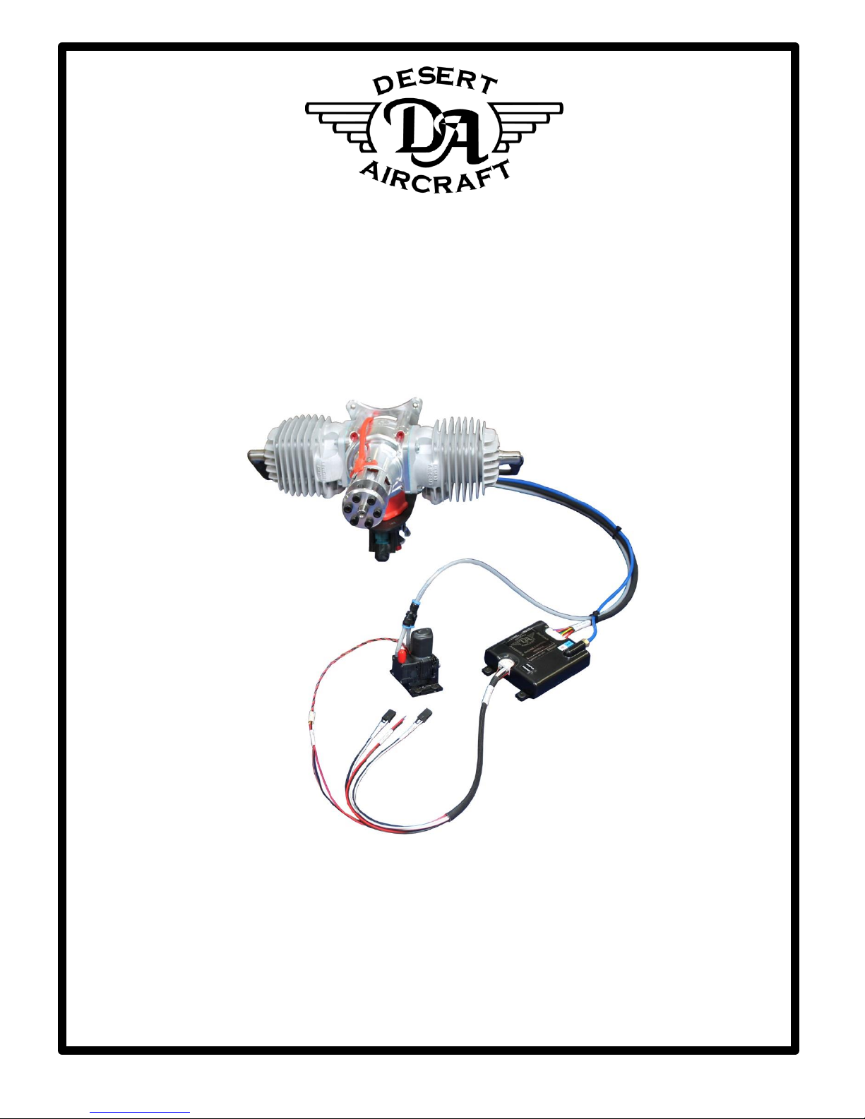
DA 100/120 EFI
Electronic Fuel Injected Engines
OWNER’S MANUAL
DESERT AIRCRAFT OWNER’S MANUAL HFEDCN0054 Rev G
2
This Document is not controlled when printed. See HFE “Released Documents” folder on server for latest revision,
or contact HFE International.
Document Revision Table
Rev.
Description of Change
Revised
by
Revision
Date
Approved
By
Approved
Date
A
Initial Release
T.West
12/29/2015
D.Gallaher
12/29/2015
B
Added ECM Blink Signals
T.West
3/28/2016
D.Gallaher
3/28/2016
C
Added Throttle Kill/UAV Instructions
K.Gratien
7/14/2016
T.West
7/14/2016
D
Updated Header
K.Gratien
3/28/2017
T.West
3/28/2017
E
Updated maintenance schedule table
T.West
11/3/2017
D.Gallaher
11/3/2017
F
Updated with Revision Table
A.Sanchez
12/14/2017
T.West
12/14/2017
G
RS-232 Callout, Maintenance change
K.Gratien
4/18/2018
T.West
4/18/18

DESERT AIRCRAFT OWNER’S MANUAL HFEDCN0054 Rev G
3
This Document is not controlled when printed. See HFE “Released Documents” folder on server for latest revision,
or contact HFE International.
Table of Contents
Section Page
1. General Safety 4
2. Un-Packing Your Engine 5
3. Getting Started 9
a. Hardware Installation 10
b. Transmitter/Receiver Set Up 11
c. Starting Engine 11
4. Maintenance 12
5. ECM Signal Data 13
a. Blink Patterns 14
6. Technical Specifications 15
a. Battery Recommendations 15
7. Warranty Information 16
8. Part Numbers 18
DESERT AIRCRAFT OWNER’S MANUAL HFEDCN0054 Rev G
4
This Document is not controlled when printed. See HFE “Released Documents” folder on server for latest revision,
or contact HFE International.
1. General Safety:
Read and understand this Owner’s Manual before operating your engine. You can help
prevent accidents by being familiar with the controls and observing safe operating
procedures.
Operator’s Responsibility:
1. The operator should know how to stop the engine quickly in case of an
emergency.
2. A safety zone around the propeller should be established in which no person
or object is allowed to enter. Install a guard around the propeller when
appropriate.
WARNING
1. Observe all safety precautions when working around the propeller.
2. Exhaust contains poisonous carbon monoxide, a colorless and odorless gas.
Breathing carbon monoxide can cause loss of consciousness and may lead to
death.
3. Never run your engine in an enclosed space. Always allow for appropriate
ventilation.
4. Observe precaution around the muffler. The exhaust system gets hot enough
to ignite some materials.
5. Keep flammable materials away from the engine.
6. Gasoline is extremely flammable and is explosive under certain conditions.
Do not smoke or allow flames or sparks where the engine is operating.

DESERT AIRCRAFT OWNER’S MANUAL HFEDCN0054 Rev G
5
This Document is not controlled when printed. See HFE “Released Documents” folder on server for latest revision,
or contact HFE International.
2. Un-Packing Your Engine:
Caution:
Your Engine comes with wire harnesses attached to the intake assembly. Handle the
engine with care when removing the assembly from the box.
Package Contents:
1. Engine with Intake Assembly
2. Engine Control Unit (ECM)
3. Main Wire Harness
4. Owner’s Manual
5. (Optional) Mufflers and Installation hardware
6. Fuel Pump
ATTENTION
Observe Precautions for Handling
Electrostatic Sensitive Devices (ESD).
The ECM and Throttle servo on this engine contain sensitive electronic hardware.
As a result, this engine is packaged in electrostatic dissipative foam and contained in
electrostatic dissipative bags. Any handling of these devices should be contained in an
ESD safe area.

DESERT AIRCRAFT OWNER’S MANUAL HFEDCN0054 Rev G
6
This Document is not controlled when printed. See HFE “Released Documents” folder on server for latest revision,
or contact HFE International.
EFI Components and Descriptions
Figure 1: Engine Control Module (ECM)
Figure 2: ECM Input Harness from Receiver
14 Pin ECM
Connector
Fuel Pump
Throttle
Command
Tach
Output
Battery
14 Pin
Connector
from Receiver
24 Pin
Connector to
Engine
Engine Vacuum
Line

DESERT AIRCRAFT OWNER’S MANUAL HFEDCN0054 Rev G
7
This Document is not controlled when printed. See HFE “Released Documents” folder on server for latest revision,
or contact HFE International.
Figure 3: Main Engine Harness
Figure 4: Assembly Hardware
Exhaust Gaskets
Fuel line between
fuel tank and fuel
pump
Vacuum line
between ECM and
engine
Fuel line between
engine and fuel
pump
Heat Shrink: used to
connect CHT sensor
to wire harness
24 Pin ECM
Connector
Engine Connector
Ignition
Connector
Crank Input

DESERT AIRCRAFT OWNER’S MANUAL HFEDCN0054 Rev G
8
This Document is not controlled when printed. See HFE “Released Documents” folder on server for latest revision,
or contact HFE International.
Figure 5: Fuel Pump
Figure 6: Engine and Crank Harness
Fuel Out to Engine
Fuel In from Fuel
Tank
Fuel Connector
Crank Position
Sensor Connector
13 Pin Engine
Harness
Connector

DESERT AIRCRAFT OWNER’S MANUAL HFEDCN0054 Rev G
9
This Document is not controlled when printed. See HFE “Released Documents” folder on server for latest revision,
or contact HFE International.
Figure 7: Intake Components
3. Getting Started:
Engine Oil
This engine was calibrated using Red Line 2 Stroke All Sport oil at a mix ratio of 40:1.
This oil type and mix ratio should be maintained to ensure that the fuel injection system
and engine operates as designed.
Oil Brand:
Red Line
Oil Type:
2 Stroke All Sport
Mix Ratio: 40:1
40 parts gasoline to one part oil.
Fuel Recommendations
Throttle Servo
Injector
MAP Fitting
Fuel Fitting

DESERT AIRCRAFT OWNER’S MANUAL HFEDCN0054 Rev G
10
This Document is not controlled when printed. See HFE “Released Documents” folder on server for latest revision,
or contact HFE International.
The engine was calibrated with premium gasoline. 91-93 octane is recommended.
a. Hardware Installation
1. Do not install the ECM to the engine or motor mount. The vibration will damage
the hardware. Route the ECM to a location inside the aircraft and mount it
where vibration is minimal. The ECM does not produce excessive heat and can
be encapsulated in foam to isolate it from vibration if needed.
2. Refer to the diagrams in section 2 for wire harness designations and
connections.
3. Install blue tube between the ECM and the manifold air pressure port on the
throttle body.
4. Install the gray tube from the fuel pump push to connect to the injector port on
the throttle body.
Figure 8: Push to Connect Diagram
Push tubing past locking ring and O-ring to produce a proper seal. Push locking
ring to release.
5. Install the fuel filter between the fuel pump inlet and the fuel tank.
6. Any 3 cell LiPo, 4 cell Lifepo4, or equivalent battery with a minimum of
2000mA/hr rating will run the engine for up to 2 continuous hours.
b. Transmitter/Receiver Set Up

DESERT AIRCRAFT OWNER’S MANUAL HFEDCN0054 Rev G
11
This Document is not controlled when printed. See HFE “Released Documents” folder on server for latest revision,
or contact HFE International.
1. Throttle commands use the standard output from Channel 3 of the receiver.
Expected pulse width range from 900µs for closed throttle and 2100µs for wide
open throttle. You may need to extend the end limits for channel 3 in your
transmitter to produce the appropriate range. Adjust the exponential rate to get
the desired throttle response.
2. (Throttle Kill) Using the DA EFI system does not require an opto kill for proper
operation. When the pulse width from the receiver falls below 960µs (5%
throttle), the ECM will remove power to both the injector and ignition system
thus stopping the operation of the engine.
3. (UAV Option) Provide power to the enable line, when power is removed ECM
will remove power to both the injector and ignition system thus stopping the
operation of the engine.
FUEL SYSTEM WARNINGS:
Do not connect the fuel port to the Manifold Air Pressure tube.
Do not exceed 15 PSI (1 bar) of fuel pressure.
c. Starting Your Engine for the First Time
1. Verify that the ECM is powered up (Blue Light on ECM).
2. Verify that the throttle setting is at about 30%.
3. Prime your system for the first time by removing the fuel line from the back of
the throttle body. Cycle the battery power to the ECM in 5 second intervals
until fuel is flowing from the fuel line. Re-install the fuel line. You should not
have to complete the priming process again unless the engine fuel system is
allowed to run dry or has been disconnected for any reason.
4. Give the prop several aggressive flips, the engine should start.

DESERT AIRCRAFT OWNER’S MANUAL HFEDCN0054 Rev G
12
This Document is not controlled when printed. See HFE “Released Documents” folder on server for latest revision,
or contact HFE International.
Note: The engine may struggle to run for the first few minutes as it is purging
all the air from the fuel system. This may not be evident until you go to wide
open throttle.
5. Allow the engine to run for a few minutes.
6. Hold at wide open throttle for 15 seconds to verify that the air in the fuel
system has been purged. Reduce the engine speed to idle.
Starting Again After First Start
Give the prop several aggressive flips, the engine should start. If the engine
does not start, increase throttle above 50% to clear possible flooded
condition. Give the prop several more aggressive flips.
4. Maintenance:
Maintenance Schedule:
Item
Before
Each
Flight
Every 50
Hours
Every 100
Hours
Every 200
Hours
Engine Oil Pre-Mix
X
Spark Plug
Check/Adjust
X
Spark Plug Replace
X
Air Filter Check/Clean
X
Air Filter Replace
X
Fuel Filter
X
HFE OEM Maintenance
X
Table I: Maintenance Items

DESERT AIRCRAFT OWNER’S MANUAL HFEDCN0054 Rev G
13
This Document is not controlled when printed. See HFE “Released Documents” folder on server for latest revision,
or contact HFE International.
5. Signal Inputs/Outputs for ECM:
Pin
Signal
Description
1
NC
Not Connected
2
NC
Not Connected
3
NC
Not Connected
4
NC
Not Connected
5
NC
Not Connected
6
IGN PWR
+6V power supply output from the Engine Control Unit for the
ignition power.
7
NC
Not Connected
8
IGN GND
Ignition Ground
9
NC
Not Connected
10
IGN SIGNAL
Modified integrator filtered output.
11
SERVO POWER
+6V power supply output from the Engine Control Unit for the
throttle servo power.
12
CRANK PWR
+5V power supply output from the Engine Control Unit for the
crank sensor.
13
SERVO GND
Throttle servo ground.
14
CRANK GND
Crank sensor ground.
15
SERVO SIGNAL
Throttle position with logic-level output. A Pulse Width
Modulated (PWM) signal at nominally 100Hz with ON time
ranging from 900µs to 2100µs corresponding to throttle
position. This pin has an 8mA draw.
16
CRANK SIGNAL
+5V logic-level digital input. Bi-polar type.
17
CHT (+)
Cylinder head temperature sensor. Variable resistance
thermistor.
18
CHT (-)
Cylinder head temperature sensor reference.
19
MAT (+)
Manifold Air Temperature sensor. Variable resistance
thermistor.
20
MAT (-)
Manifold Air Temperature sensor reference.
21
NC
Not Connected
22
NC
Not Connected
23
INJECTOR GND
Injector Switching to Ground. Frequency matches engine RPM.
24
INJECTOR POWER
Battery voltage.
Table II:Main ECM 24 Pin Connector

DESERT AIRCRAFT OWNER’S MANUAL HFEDCN0054 Rev G
14
This Document is not controlled when printed. See HFE “Released Documents” folder on server for latest revision,
or contact HFE International.
Pin
Signal
Description
1
NC
Not Connected (RS-232 level Tx)
2
PUMP SIGNAL
Variable voltage output from fuel pump assembly.
3
NC
Not Connected (RS-232 level Rx)
4
NC
Not Connected
5
GND
Crank signal output ground reference
6
PUMP (+)
Fuel System power (routed internally from system power pin
14 and enabled by a high side driver (relay) from ECM state
commands).
7
TACH OUT
+5V logic-level digital output. This pin has a maximum
continuous load of ±20mA. Output signal has a 50% duty cycle.
8
PUMP (-)
Fuel system ground reference.
9
THROTTLE SIGNAL
Throttle position with logic-level input. A Pulse Width
Modulated (PWM) signal at nominally 50Hz with ON time
ranging from 900µs to 2100µs corresponding to throttle
position (0% to 100%). This pin has an 8mA draw.
10
GND
Throttle input ground reference.
11
ENABLE
(Special feature
available on request)
Engine enable signal from AP. A 5 volt signal present to enable
(UAV option only). This pin has an 8mA draw. 10k pull down
resistor.
12
GND
Enable ground reference
13
MAIN GND
Main Ground
14
POWER 12V
Main power input. 10 to 14 volts. Maximum power draw is 12
W at wide open throttle. (11.1v 3 cell LiPo 2000ma or bigger)
Table III:ECM Input Connector 14 Pin
a. ECM Blink Patterns:
If the engine is not starting, checking the STATUS light on the top of the ECM can signal what
problem is seen by the ECM. The pattern repeats after 3 second pause, and blinks at 1 to 2 Hz.
# of Blinks
Issue
1
High battery disconnected
2
MAT disconnected/no signal
3
CHT disconnected/no signal
5
Pulse train (throttle) not active
Table IV:Blink Patterns

DESERT AIRCRAFT OWNER’S MANUAL HFEDCN0054 Rev G
15
This Document is not controlled when printed. See HFE “Released Documents” folder on server for latest revision,
or contact HFE International.
6. Technical Specifications
Throttle Body air cleaner retaining nuts.
10 in-lbs.
Only use NGK CM-6 spark plugs.
Plug gap is .018” to .020" (.38 to .50 mm)
Size Torque
Spark plug: CM-6, 10mm 90 in. lbs.
Steel prop bolts: M5x 50mm 90 in. lbs. /carbon props.
Aluminum crankcase bolts: M5x16mm 70 in. lbs.
Aluminum cylinder base bolts: M5x16mm 60 in. lbs.
Steel cylinder base bolts: M5x16mm 95 in. lbs.
Air Filter Cap nuts: M5x75mm 10 in. lbs.*
Steel motor mount bolts: M6x16mm 120 in. lbs.
*Caution: Care must be taken to not over tighten the TBI mounting bolts. Over
tightening can distort and damage the injected molded reed valve parts, rubber
gaskets, and throttle body.
a. Battery Recommendations:
Any 3 cell Lipo battery or equivalent battery pack with an amp hour capacity of
2000mA/hr or greater will run the engine for 2 hours continuously.
Using a 4 cell Lifepo4 is also permitted as its output voltage range is with in the 14 to
10 volt range.
DESERT AIRCRAFT OWNER’S MANUAL HFEDCN0054 Rev G
16
This Document is not controlled when printed. See HFE “Released Documents” folder on server for latest revision,
or contact HFE International.
7. Warranty
Thank you for choosing a Desert Aircraft Product.
Your Total satisfaction is our #1 priority.
If you have any questions on the installation and operation of this engine, please contact us
directly. Please have your engine serial number on hand when calling for service.
Desert Aircraft Fuel Injected Engine Customer Service:
Phone: 520.722.0607
Email: [email protected]
1815 South Research Loop
Tucson, Arizona 85710
U.S.A
Engine Core Warranty
Your DA120 motor and ignition system are covered with a 3 year warranty
by Desert Aircraft, starting from the date of purchase.
This warranty covers defects in workmanship and materials only.
Do not disassemble the motor or ignition system. Disassembly of the motor or
ignition system can void the warranty on that item.
Any modifications to the motor, or the ignition system, other than those authorized
by Desert Aircraft, will void this warranty.
This warranty does not cover the following:
Shipping expenses to and from Desert Aircraft for warranty service.
Damage caused by improper handling, operation, or maintenance.
Damage caused by a crash.
Damage caused by using improper fuel or additives.
Damage incurred during transit to Desert Aircraft. WRAP AND PACK ENGINE
CAREFULLY!!
NOTE: DESERT AIRCRAFT WILL NOT SHIP ANY WARRANTY
REPLACEMENT ITEMS UNTIL POSSIBLY DEFECTIVE ITEMS IN
QUESTION ARE RECEIVED BY DESERT AIRCRAFT.
DESERT AIRCRAFT OWNER’S MANUAL HFEDCN0054 Rev G
17
This Document is not controlled when printed. See HFE “Released Documents” folder on server for latest revision,
or contact HFE International.
EFI System Warranty
Your Desert Aircraft EFI system is covered with a 1 year warranty by Desert
Aircraft starting from the date of shipment from Desert Aircraft.
This warranty covers defects in workmanship and materials only to include Fuel Pump,
wiring, ECM and throttle body.
Do not disassemble the ECM or Throttle Body assembly. Disassembly of the ECM or
Throttle Body assembly will void the warranty on that item.
Any modifications to the ECM, or Throttle Body assembly, other than those authorized
by Desert Aircraft, will void this warranty.
This warranty does not cover the following:
Shipping expenses to and from Desert Aircraft for warranty service.
Damage caused by improper handling, operation, or maintenance.
Damage caused by a crash.
Damage caused by using improper fuel or additives.
Damage incurred during transit to Desert Aircraft.
NOTE: DESERT AIRCRAFT WILL NOT SHIP ANY WARRANTY
REPLACEMENT ITEMS UNTIL POSSIBLY DEFECTIVE ITEMS IN
QUESTION ARE RECEIVED BY HFE INTERNATIONAL.

DESERT AIRCRAFT OWNER’S MANUAL HFEDCN0054 Rev G
18
This Document is not controlled when printed. See HFE “Released Documents” folder on server for latest revision,
or contact HFE International.
8. Part Numbers
Compact Parts

DESERT AIRCRAFT OWNER’S MANUAL HFEDCN0054 Rev G
19
This Document is not controlled when printed. See HFE “Released Documents” folder on server for latest revision,
or contact HFE International.
ITEM NO.
PN
DESCRIPTION
QTY.
1
DA120EFI-1
20MM THROTTLE BODY ASSY
1
1.1
DA120EFI-2
20MM THROTTLE SHAFT
1
1.2
DA120EFI-3
20MM THROTTLE PLATE
1
1.3
DA120EFI-4
THROTTLE BODY HOUSING
1
1.4
DA120EFI-5
THROTTLE SCREW
1
1.5
DA120EFI-6
GROMMET MODIFIED
1
2
DA120EFI-7
INJECTOR CAP MODIFIED
1
3
DA120EFI-8
ISOLATOR
2
4
DA120EFI-9
AIR FILTER ASSEMBLY
1
4.1
DA120EFI-10
AIR FILTER CAP
1
4.2
DA120EFI-11
DA 100 AIR FILTER BASE
1
4.3
DA120EFI-12
DA 100 AIR FILTER FOAM
1
4.4
DA120EFI-13
FILTER
1
5
DA120EFI-14
HITEC HS-5085MG MOD.
1
6
DA120EFI-15
M3X25 SCREW
2
7
DA120EFI-16
M3X30 SCREW
2
8
DA120EFI-17
20MM ALLTHREAD ASSEMBLY
2
8.1
DA120EFI-18
20MM M5 ALLTHREAD
1
8.2
DA120EFI-19
M5X0.8 THUMB NUT 18-8 SS
1
9
DA120EFI-20
20MM INJECTOR ASSEMBLY
1
10
DA120EFI-21
LINKAGE LARGE 20MM
1
10.1
DA120EFI-22
20MM THROTTLE HORN
1
10.2
DA120EFI-23
20/25MM MAIN LINK
1
10.3
DA120EFI-24
SERVO ARM MODIFIED
1
10.4
DA120EFI-25
PHMS 2-56 X 7/32 18-8 SS
2
10.5
DA120EFI-26
SS BALL BEARING 3/16 OD
2
11
DA120EFI-27
VELOCITY STACK WITH MAT
1
11.1
DA120EFI-28
20MM VELOCITY STACK
1
11.2
DA120EFI-29
DA MAT SENSOR
1
12
DA120EFI-30
M2.3-40-M-SS-P
1
13
DA120EFI-31
M5 TO 1/16 BARB FITTING
3
14
DA120EFI-32
BHCS M2X0.4 4MM 18-8 SS
1
15
DA120EFI-33
VITON ORING 1.5MM 9MM ID
1
16
DA120EFI-34
NYLON LOCKNUT M5X0.8
2
17
DA120EFI-35
WASHER M2 2.2MM ID 5MM OD
1
18
DA120EFI-36
M5 MALE THREAD TO LARGE BARB
3
19
DA120EFI-37
REED BLOCK
1
20
DA120EFI-38
4MM FESTO WHITE TUBING
1
21
DA120EFI-39
POLYURETHANE TUBING, 1/16
1
22
DA120EFI-40
LARGE TUBING
1
23
DA120EFI-41
14 PIN WIRE HARNESS
1
24
DA120EFI-42
24 PIN WIRE HARNESS
1
25
DA120EFI-43
FUEL PUMP
1
26
DA120EFI-44
ECU
1
27
DA120EFI-45
13 PIN WIRE HARNESS
1
28
DA120EFI-46
20MM VELOCITY STACK COMPACT
1
29
DA120EFI-47
M5X75 SCREW
1
Table V: Part Numbers
This manual suits for next models
1
Table of contents
Other Desert Aircraft Engine manuals

Desert Aircraft
Desert Aircraft DA85 User manual

Desert Aircraft
Desert Aircraft DA100-I User manual

Desert Aircraft
Desert Aircraft DA50 EFI User manual

Desert Aircraft
Desert Aircraft DA-215 User manual

Desert Aircraft
Desert Aircraft DA200 User manual

Desert Aircraft
Desert Aircraft DA120 User manual

Desert Aircraft
Desert Aircraft DA170 User manual

Desert Aircraft
Desert Aircraft DA35 User manual

Desert Aircraft
Desert Aircraft DA100 User manual


