Desert Aire CM3540 Series User manual

Installation and Operation Manual
for LW units
A
dvanced program
capabilities.
Internal Display
Te
rminal (IDT)
Multiple communication
interface options:
- LonW
orks®
- BACnet™ Ethernet
- BACnet™ MS/TP
- Modbus
®
Precise temperature
and humidity control.
CM3540 Series
Controller

2

3
DANGER
ONLY TRAINED, QUALIFIED PERSONNEL SHOULD INSTALL AND/OR SERVICE
DESERT AIRE EQUIPMENT. SERIOUS INJURY, DEATH AND PROPERTY DAMAGE CAN
RESULT FROM IMPROPER INSTALLATION/SERVICE OF THIS EQUIPMENT. HIGH VOLTAGE
ELECTRICAL COMPONENTS AND REFRIGERANT UNDER PRESSURE ARE PRESENT.
Desert Aire Dehumidication Equipment
Standard Limited Warranty
Desert Aire warrants the dehumidifying unit to be free from defects in materials and workmanship subject to the terms,
conditions and limitations stated herein.
TERMS
Desert Aire warrants all components (except as noted) for a period of two (2) years from the date of shipment. This
warranty shall be limited to the supply of new or rebuilt parts for the part which has failed because of
defects in workmanship or material, and does not include the cost for labor, transportation or other costs not herein
provided for. Replaced parts are warranted only for the remaining portion of the original warranty period.
CONDITIONS
The warranty is subject to the following conditions:
1. The unit must be properly installed and maintained in accordance with the Desert Aire
“Installation and Operation Manual” provided with each unit and/or other documentation provided.
2. The Start-Up Report must be completed and returned to Desert Aire Service for evaluation. If no
decienciesareidentiedaWarrantyValidationLetterwillbeissuedthatprovidesallwarranty
datesandcoverage.Ifinstallationorstart-updecienciesarepresent,thesemustbecorrected
and communicated to Desert Aire in order to activate warranty.
3. This warranty shall not apply to any part that has been tampered with, or has been subject to
misuse, negligence or accident. A warranty can be obtained for altered equipment but only with
written consent from Desert Aire.
4. The following parts and components are excluded from the warranty: belts, lters, driers, fuses and
refrigerant.
5. Refrigerant coils or other components that corrode due to improperly balanced pool chemistry or
corrosive air quality will not be warranted.
6. All replacements or repairs will be FOB Germantown, WI.
7. This warranty shall be null and void if defects or damages result from unauthorized opening of the
refrigerant circuit, tampering with factory set controls, or operating outside the original design
conditions.
8. Desert Aire shall not be liable for labor costs incurred in diagnosing the problem, or the removal
or replacement of the part or parts being repaired.
9. Desert Aire must preauthorize all warranty coverage described herein.
Desert Aire - CM3540 Manual

4
ExtendedWarranty:
Your Desert Aire unit may have extended warrantees beyond this Standard Limited Warranty document.
Extended warrantees are only available at the time of the purchase of the original equipment. These extended
warrantees are covered under a separate document and their terms and conditions are separate from this
document. It is mentioned in this document for informational purposes only. Any Extended Warranties will be
identied on the Warranty Validation Letter.
Any and all incidental or consequential damages are expressly excluded from this warranty. Some states do not allow
the exclusion of incidental or consequential damages for personal injury, so the above limitations may not apply to you
for certain damages. This warranty gives you specic legal rights, and you may also have other rights, which vary
from state to state. No person or representative is authorized to make any warranty or assume any liability not strictly
in accordance with the aforementioned.
Inquiries regarding warranty matters should be addressed to:
Desert Aire Corp
c/o Service Manager
N120 W18485 Freistadt Road
Germantown, WI 53022
PH: (262) 946-7400
TOLL FREE: (800) 443-5276
FAX: (262) 946-7401
Additional copies of this manual can be purchased for a nominal fee from Desert Aire. Desert Aire also posts the
most current revision of our I/O Manuals on our website. For a digital copy of the I/O Manual for your unit revision,
please submit request to the contact information listed above.
Desert Aire - CM3540 Manual

5
ProductWarningfortheStateofCalifornia
Desert Aire - CM3540 Manual

6Desert Aire - CM3540 Manual

7
TABLEOFCONTENTS
1. Installation ........................................................................................................................ 9
1.1 Humidity and Temperature Control Package
..........................................................
9
1.2 Sensor Installation .................................................................................................. 9
1.2.1 Duct-Mount Temperature and Relative Humidity Sensor
.............................
9
1.2.2 Zone-Mount Temperature and Relative Humidity Sensor
............................
9
2. LW Controller Details ..........................................................
.............................................
11
2.1 Menu Overview and General Instructions
...............................................................
11
2.2 Main Menu
..............................................................................................................
1 2
2.2.1 Status Menu ................................................................................................. 13
2.2.1.1 Unit Status ..................................................................................... 13
2.2.1.2 I/O Status ....................................................................................... 14
2.2.1.2.1 Digital Inputs .................................................................. 15
2.2.1.2.2 Analog Inputs ................................................................. 15
2.2.1.2.3 Digital Outputs ............................................................... 16
2.2.1.2.4 Analog Outputs .............................................................. 17
2.2.1.3 Pressure Cut-outs
..........................................................................
17
2.2.2 Unit Setpoints ................................................................................................ 18
2.2.3 Occupancy Menu .......................................................................................... 18
2.2.3.1 Schedule Options ........................................................................... 19
2.2.3.1.1 Current Schedule .......................................................... 19
2.2.3.2 Temporary Holidays ....................................................................... 20
2.2.3.3 Annual Holidays ............................................................................. 20
2.2.3.4 Temporary Occupancy ................................................................... 21
2.2.3.5 Set Time ......................................................................................... 22
2.2.4 Service Menu ................................................................................................ 22
2.2.4.1 Deadbands ..................................................................................... 23
2.2.4.2 Differentials .................................................................................... 24
2.2.4.3 Sensor Offsets ............................................................................... 25
2.2.4.4 Air Heat Settings ............................................................................ 25
2.2.4.5 Condenser Settings ....................................................................... 26
2.2.5 Unit Revision ................................................................................................. 27
3. Alarms
..................................................................................................................................
29
3.1. Alarm Menu ............................................................................................................. 29
3.1.1. Alarm Screen ............................................................................................ 29
3.1.2. Low Suction Pressure ............................................................................... 29
3.1.3. High Discharge Pressure .......................................................................... 30
3.1.4. Compressor Overload ............................................................................... 30
Desert Aire - CM3540 Manual

8
3.1.5. Blower Overload ....................................................................................... 30
3.1.6. Alarm History Screen ................................................................................ 30
4. Hardware Details .............................................................................................................. 33
4.1. Programmable Controller
........................................................................................
33
4.2. Suction Pressure Transducer
.................................................................................
33
4.3. Discharge Pressure Transducer ............................................................................ 33
4.4. Defrost and Ambient Temperature Sensor ............................................................. 34
4.5. Zone Air Temperature / Relative Humidity Sensor ................................................. 34
5. Appendix ............................................................................................................................ 35
Desert Aire - CM3540 Manual

9
1. Installation
1.1. Humidity and Temperature Control Package
Your Desert Aire CM3540 controller is designed for precise monitoring and control of air
temperature and relative humidity (RH) within a conditioned environment.
This CM3540 control system is easy to install and operate. It features a display mounted
on the controller face which allows you to view and adjust set points and modes of
operation. It also indicates the operating status of major components inside of the
dehumidier.
Most sensors and inputs have been factory-installed and wired inside of the
dehumidier. An additional sensor, included in the control assembly, needs to be mounted
in the return air duct or the zone to be conditioned. This device senses the conditioned
zone air temperature and relative humidity to control the LW dehumidier. For BMS Points
Lists please send inquiry to [email protected] and include your model number, serial
number and BMS protocol.
1.2. Sensor Installation
1.2.1. Duct-Mount Temperature and Relative Humidity Sensor
The duct-mount return air temperature and relative humidity sensor is used to
select the operational modes of the dehumidier and provide consistent conditions
throughout the space.
Install the duct-mount sensor in the return air duct of the dehumidier. CAUTION:
Do not mount the sensor in a section of duct where false readings may occur due
to stratication, solar heat gain, thermal losses in winter or where water is likely to
drip on it.
Note: If the sensor is installed outdoors, it must be mounted within a weatherproof
enclosure.
Install using 24-16 AWG stranded wire; 18 AWG stranded wire recommended.
Do not run sensor wiring adjacent to, OR in the same conduit as, wires carrying
more than 24 VAC. See manufacturer’s specications for more details.
1.2.2. Zone-Mount Temperature and Relative Humidity Sensor
In cases where a return duct is not used, a zone temperature and relative humidity
sensor is used to select the operational modes of the dehumidier and provide
consistent conditions in the zone.
Desert Aire - CM3540 Manual

10
Install the zone-mount sensor in an area representative of the zone conditions,
shielded from any abnormal external heat or humidity sources. CAUTION: Do not
mount the sensor in any area where false readings may occur due to
stratication, solar heat gain, thermal losses or inuenced by supply air diffusers.
Install using 24-16 AWG stranded wire; 18 AWG stranded wire is recommended.
Do not run sensor wiring adjacent to, OR in the same conduit as, wires carrying
more than 24 VAC. See manufacturer’s specications for more details.
Desert Aire - CM3540 Manual

11
2. LWControllerDetails
Figure 1
2.1. MenuOverviewandGeneralInstructions(Figures1and2)
Your Desert Aire CM3540 Controller is pre-programmed and congured at the factory for
use in the application specied. The internal display (IDT – Figure 1) allows the operator to
monitor the operation and adjust the set points of your Desert Aire LW dehumidier.
The IDT has an LCD screen and six keys. The keys from left to right are:
The Home Screen displaying the Desert Aire logo (Figure 2) can show three items.
The current Zone Relative Humidity and Temperature will always be shown on the bottom
two lines of this screen. Also, if the unit is in an alarm mode, ALARM will be ashing on the
top line of this screen. The “LW” in the upper right of the screen indicates the product series of
the program installed in the controller. Below this line, “Esc Menu” indicates that
if the Esc key is pressed, the Main Menu will be displayed. Pressing Esc on any other
screen will take you back one screen.
Desert Aire - CM3540 Manual

12
Figure 2
Menu screens allow the user to select from a series of actions. The action that is
capitalized on the screen is selected by pressing the ENTER key. To cycle through the
selections on a menu screen, use the UP and DOWN keys.
If set points or selections can be altered on a screen, the ENTER key will cycle through
those items. Once the cursor is over an item, the UP and DOWN arrow keys will modify
the setting. Numeric values require that the ENTER key be pressed to accept the value.
An “on” or “off” selection will be altered as soon as the UP or DOWN keys are pressed.
To view the alarms from any menu, simply press the ALARM key. The UP and DOWN
keys will display any active alarm. When an alarm is triggered, the top line of the display
will ash “ALARM” and continues ashing until the alarm is acknowledged. Alarm
acknowledgement and history instructions are shown on the main Alarm Screen. To
escape from the alarm screens, press the Esc key until the Home Screen is displayed.
Screens which display a small up arrow in the upper right and a small down arrow in the
lower right are part of a series of screens which can be accessed by pressing either the
UP or DOWN arrow keys. If the operator has not pressed a key for an hour, the terminal
display will return to the Home Screen.
2.2. MainMenu(Figure3)
Pressing the Esc key from the Home Screen displays the MAIN MENU. This menu
allows the operator to select the STATUS MENU, Unit Set points, Occupancy Menu,
Service Menu or Unit Revision.
To return to the HOME SCREEN, press the Esc key.
Desert Aire - CM3540 Manual

13
Figure 3
2.2.1. StatusMenu(Figure4)
Selecting the STATUS MENU from the MAIN MENU allows access to the Unit
Status, I/O Status or the Pressure Cut-outs screen.
To return to the MAIN MENU, press the Esc key.
Figure 4
2.2.1.1UnitStatus(Figure5)
Selecting Unit Status from the STATUS MENU displays a text explanation
of the unit.
If a remote condenser is available, the screen displays “RC Available.” If no
remote condenser is available, the screen displays “RC Unavailable.” The
occupied state is listed either as “Occupied” or “Un-Occupied.” The Unit
Status will show one of the following states:
• Unit Off/Satised
• Heating Required
• Cooling Required
Desert Aire - CM3540 Manual

14
• Dehumidifying
• Dehum / Heat
• Dehum / Cool
The Compressor “On” or “Off” status will be shown. If “Timing” is shown
on the compressor line of the display, this indicates the compressor is
required, but is being held off until the compressor protection timer
times out. Since the unit can be commanded OFF from the BMS
communication card, the last line indicates this command state. The
current date and time will also be shown.
To return to the Unit Status Menu, press the Esc key.
Figure 5
2.2.1.2I/OStatus(Figure6)
Selecting the I/O Status from the STATUS MENU displays Digital Inputs,
Analog Inputs, Digital Outputs and Analog Outputs.
To return to the Unit Status Menu, press the Esc key.
Figure 6
Desert Aire - CM3540 Manual

15
2.2.1.2.1DigitalInputs(Figure7)
The Digital Inputs Screen shows the state of the contacts wired into
ports J2 and J12 of the controller. This screen is provided for
troubleshooting the control system.
• Occupied: “On” if this contact is made, and “Off”
if this contact is open.
• System On/Off: “On” allowing the system to run,
and “Off” to shutdown the system.
• Blower O/L: “On” if no overload exists, and “Off”
if the blower motor has overloaded.
• Comp O/L: “On” if the overload exists, and “Off”
if the compressor motor has overloaded.
Note: Refer to the CM3540 electrical schematics for
point identication.
To return to the I/O STATUS, press the Esc key.
Figure 7
2.2.1.2.2AnalogInputs(Figure8)
The Analog Inputs Screen shows the state of the contacts wired into
ports J2 of the controller. This screen is provided for troubleshooting
the control system. The Analog Inputs Screen shows the current
readings of the Zone Relative Humidity, Zone Temperature, Return Air
Temperature, Suction Line Temperature, Suction Pressure and
Discharge Pressure.
To return to the I/O STATUS, press the Esc key.
Desert Aire - CM3540 Manual

16
Figure 8
2.2.1.2.3DigitalOutputs(Figure9)
The Digital Outputs Screen shows the state of the devices wired into
ports J3, J10 and J11 of the controller. This screen is provided for
troubleshooting the control system.
• Reheat Sol: Turns on the remote condenser solenoid
for reheat.
• Heating: Turns on any auxiliary heat for the space.
• Compressor: Turns on the compressor.
• Supply Blwr: Turns on the supply air blower.
• Defrost Sol: Turns on the defrost solenoid.
• Liquid Sol: Turns on the liquid solenoid.
• Occupancy: Turns on the occupancy relays.
Note: Refer to the CM3540 electrical schematic for point identication.
Figure 9
Desert Aire - CM3540 Manual

17
2.2.1.2.4AnalogOutputs(Figure10)
The Analog Outputs Screen shows the position of the devices wired
into port J9 of the controller. This screen is provided for
troubleshooting the control system.
• 1 Unused Output
• 2 Mod Heat: Modulating air heat output displayed
from 0-100%
To return to the I/O STATUS, press the Esc key.
Figure 10
2.2.1.3PressureCut-outs(Figure11)
The Pressure Cutouts Screen displays the refrigerant high discharge
pressure and low suction pressure cut-out values for both refrigerant
circuits. These pressure settings are factory-set and cannot be changed
by the operator.
To return to the STATUS MENU, press the Esc key.
Figure 11
Desert Aire - CM3540 Manual

18
2.2.2. UnitSetpoints(Figure12)
Selecting the Set points from the MAIN MENU will display the Zone Set points screen.
The Zone Temperature and Zone R.H. allow the zone condition set points to be
modied. To modify these set points, press the ENTER key until the desired set point
is selected and use the arrow keys until the desired setting is shown. The range of
the Zone Temperature Setpoint is 32.0° to 99.9°F. The range of the Zone Humidity
Setpoint is 0.0% RH to 99.9% RH. Press the ENTER key to accept the set point value.
This screen also displays the actual conditions from the zone sensor in the conditioned
space.
To return to the MAIN MENU, press the Esc key.
Figure 12
2.2.3.OccupancyMenu(Figure13)
Select the SCHEDULE SETUP from the MAIN MENU to show the OCCUPANCY
SCHEDULE MENU. From this menu you can access and adjust the Schedule Options,
Temporary Holidays, Annual Holidays, Temporary Occupancy and Time settings.
To return to the MAIN MENU, press the Esc key.
Figure 13
Desert Aire - CM3540 Manual

19
2.2.3.1ScheduleOptions(Figure14)
This screen allows you to set the number of active occupancy schedules.
Setting at least one active schedule allows the occupancy schedule
timing to be set from the Current Schedule Screen. If the number of active
schedules is left at zero, no occupancy scheduling will be active.
To return to the OCCUPANCY MENU, press the Esc key.
Figure 14
2.2.3.1.1CurrentSchedule(Figure15)
The bottom of this screen allows you to set the occupancy timing for
the selected Day Of Week (DOW).
• Select the schedule to modify the Start and Stop Times. This
is the time span that the unit will be in occupied mode.
All times are set in the 24-hour format.
• As the DOW is selected, the UP and DOWN keys allow for
Monday, Tuesday, Wednesday, Thursday, Friday, Saturday,
Sunday and any holiday to be occupied during that time.
• Up to 10 schedules can be active at any time. These allow for
different start and stop times on various days of the week,
weekends or programmed holidays.
To return to the OCCUPANCY MENU, press the Esc key.
Desert Aire - CM3540 Manual

20
Figure 15
2.2.3.2TemporaryHolidays(Figure16)
The Temporary Holiday settings are for holidays that change dates from year
to year, such as Memorial Day or Thanksgiving. Up to 10 different temporary
holidays can be set from this screen. Select the number to assign to the
Annual Holiday and then select the Start Date and the End Date for that holiday.
To return to the OCCUPANCY MENU, press the Esc key.
Figure 16
2.2.3.3AnnualHolidays(Figure17)
The Annual Holiday settings are for holidays with dates that remain constant
year to year, such as New Years Day and the 4th of July. Up to 10 different
annual holidays can be set from this screen. Select the number to assign to
the Annual Holiday and then select the Start Date and the End Date for that
holiday.
To return to the OCCUPANCY MENU, press the Esc key.
Desert Aire - CM3540 Manual
Other manuals for CM3540 Series
1
Table of contents
Other Desert Aire Controllers manuals
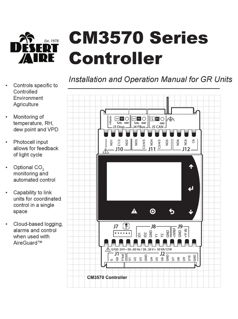
Desert Aire
Desert Aire CM3570 Series User manual
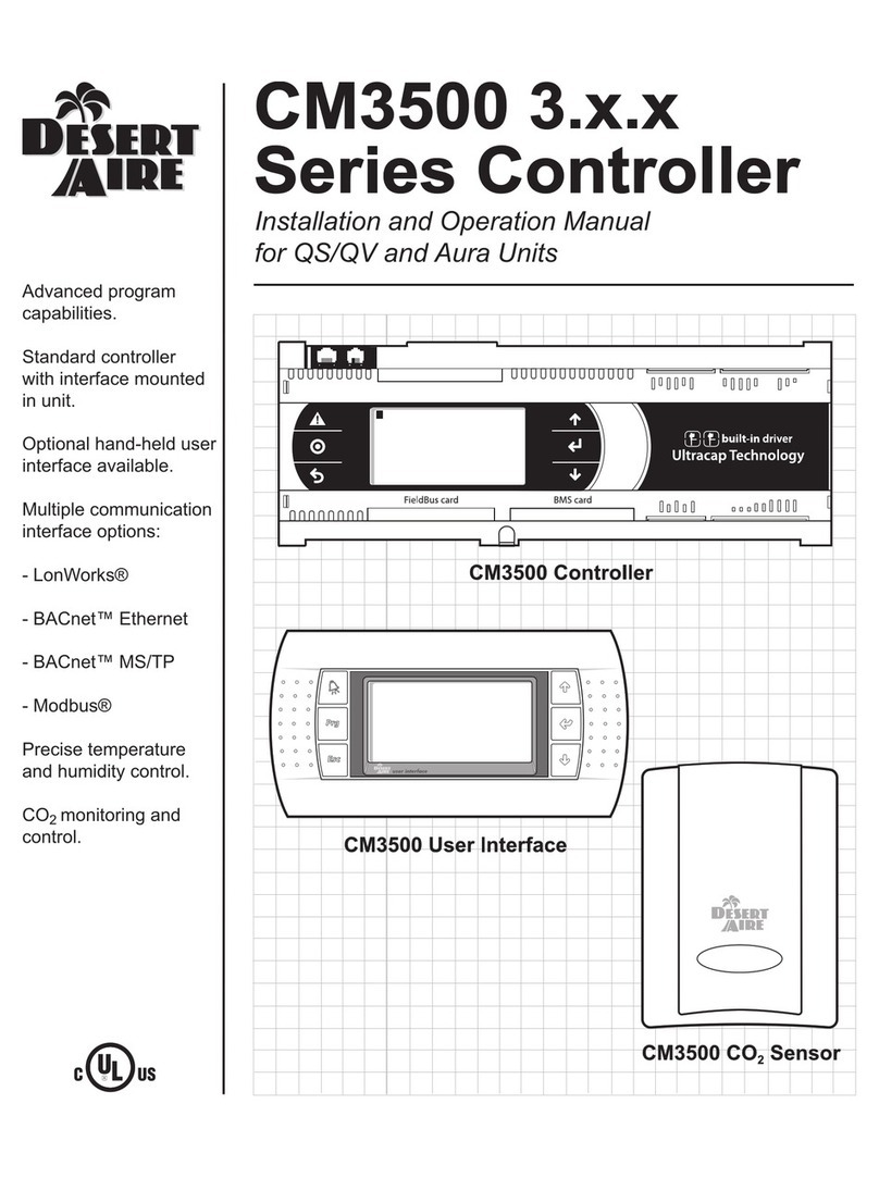
Desert Aire
Desert Aire CM3500 Series User manual

Desert Aire
Desert Aire CM3510 Series User manual
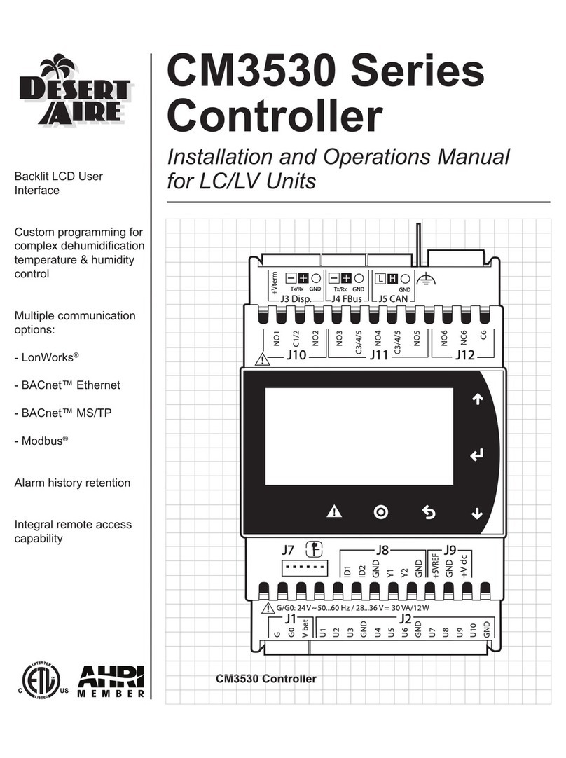
Desert Aire
Desert Aire CM3530 Series User manual
Desert Aire
Desert Aire CM3550 Series User manual
Desert Aire
Desert Aire CM3554 Series User manual

Desert Aire
Desert Aire CM35xx User manual
Desert Aire
Desert Aire CM3560 Series User manual
Desert Aire
Desert Aire CM3540 Series User manual
Desert Aire
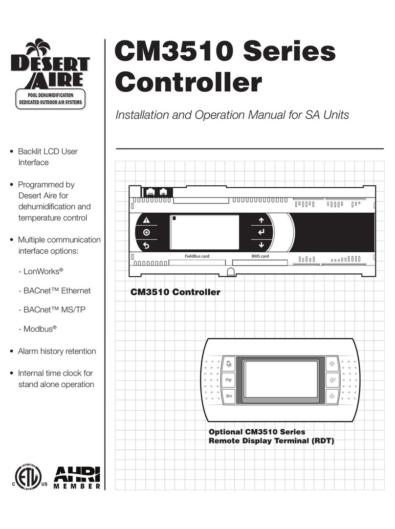
Desert Aire CM3510 Series User manual
