Desert Aire CM3570 Series User manual

Installation and Operation Manual for GR Units
• Advanced program
capabilities
• Internal Display
Terminal (IDT)
• Multiple
communication
interface options:
- LonWorks®
- BACnet™ Ethernet
- BACnet™ MS/TP
- Modbus®
• Precise temperature
and humidity control
CM3570 Series
Controller
7
CM3570 Series
Controller
Installation and Operation Manual for GR Units
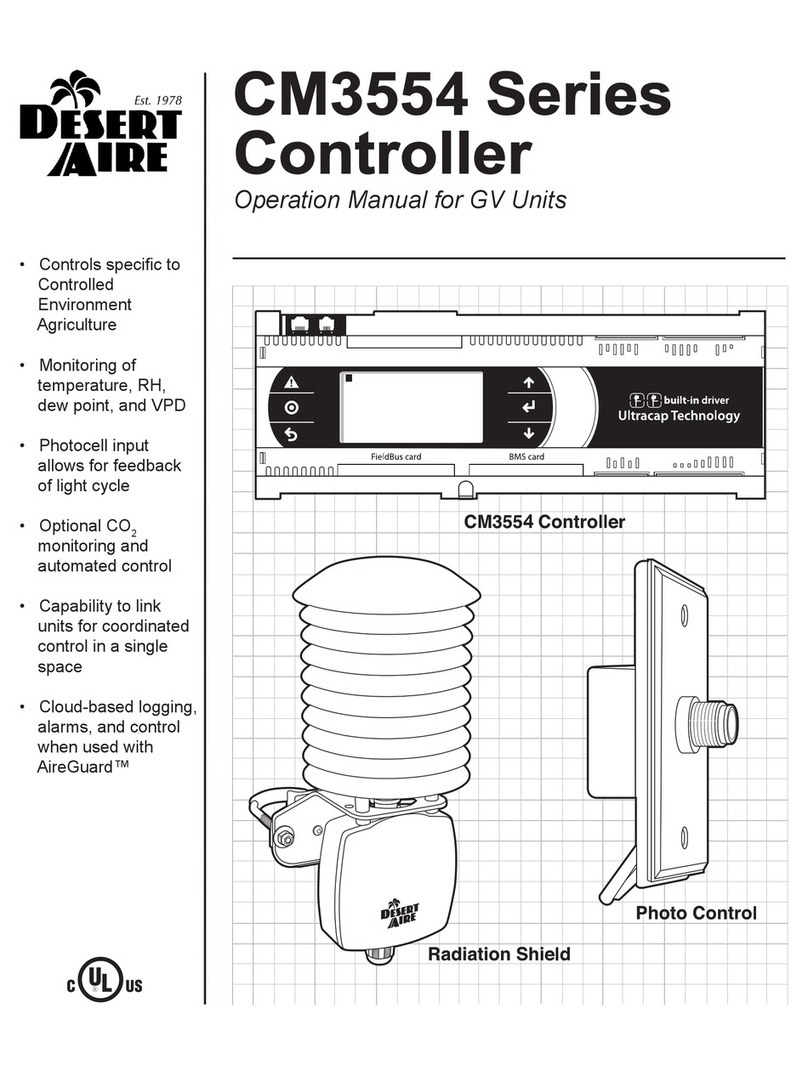
• Controls specic to
Controlled
Environment
Agriculture
• Monitoring of
temperature, RH,
dew point and VPD
• Photocell input
allows for feedback
of light cycle
• Optional CO2
monitoring and
automated control
• Capability to link
units for coordinated
control in a single
space
• Cloud-based logging,
alarms and control
when used with
AireGuard™

2

3
DANGER
ONLY TRAINED, QUALIFIED PERSONNEL SHOULD INSTALL AND/OR SERVICE
DESERT AIRE EQUIPMENT. SERIOUS INJURY, DEATH AND PROPERTY DAMAGE CAN
RESULT FROM IMPROPER INSTALLATION/SERVICE OF THIS EQUIPMENT. HIGH VOLTAGE
ELECTRICAL COMPONENTS ARE PRESENT.
Desert Aire
Dehumidication Equipment Standard Limited Warranty
Desert Aire warrants the dehumidifying unit to be free from defects in materials and workmanship subject to the terms,
conditions and limitations stated herein.
TERMS
Desert Aire warrants all components (except as noted) for a period of two (2) years from the date of shipment. This
warranty shall be limited to the supply of new or rebuilt parts for the part which has failed because of defects in
workmanship or material, and does not include the cost for labor, transportation or other costs not herein provided for.
Replaced parts are warranted only for the remaining portion of the original warranty period.
CONDITIONS
The warranty is subject to the following conditions:
1. The unit must be properly installed and maintained in accordance with the Desert Aire
“Installation and Operation Manual” provided with each unit and/or other documentation provided.
2. The Start-Up Report must be completed and returned to Desert Aire Service for evaluation. If no
deciencies are identied a Warranty Validation Letter will be issued that provides all warranty dates
and coverage. If installation or start-up deciencies are present, these must be corrected and
communicated to Desert Aire in order to activate warranty.
3. This warranty shall not apply to any part that has been tampered with, or has been subject to
misuse, negligence or accident. A warranty can be obtained for altered equipment but only with
written consent from Desert Aire.
4. The following parts and components are excluded from the warranty: lters and fuses.
5. Coils or other components that corrode due to corrosive air quality will not be warranted.
6. All replacements or repairs will be FOB Germantown, WI.
7. This warranty shall be null and void if defects or damages result from unauthorized tampering with
factory set controls, or operating outside the original design conditions.
8. Desert Aire shall not be liable for labor costs incurred in diagnosing the problem, or the removal
or replacement of the part or parts being repaired.
9. Desert Aire must preauthorize all warranty coverage described herein.
Desert Aire - CM3570 Manual

4
Extended Warranty:
Your Desert Aire unit may have extended warrantees beyond this Standard Limited Warranty document. Extended
warrantees are only available at the time of the purchase of the original equipment. These extended warrantees are
covered under a separate document and their terms and conditions are separate from this document. It is mentioned
in this document for informational purposes only. Any Extended Warranties will be identied on the Warranty
Validation letter.
Any and all incidental or consequential damages are expressly excluded from this warranty. Some states do not allow
the exclusion of incidental or consequential damages for personal injury, so the above limitations may not apply to you
for certain damages. This warranty gives you specic legal rights, and you may also have other rights, which vary
from state to state. No person or representative is authorized to make any warranty or assume any liability not strictly
in accordance with the aforementioned.
Inquiries regarding warranty matters should be addressed to:
Desert Aire Corp
c/o Service Manager
N120 W18485 Freistadt Road
Germantown, WI 53022
PH: (262) 946-7400
FAX: (262) 946-7401
Additional copies of this manual can be purchased for a nominal fee from Desert Aire. Desert Aire also posts the most
current revision of our I/O Manuals on our website. For a digital copy of the I/O Manual for your unit revision, please
submit request to the contact information listed above.
Desert Aire - CM3570 Manual

5
Product Warning for the State of California:
Desert Aire - CM3570 Manual

6Desert Aire - CM3570 Manual

7
TABLE OF CONTENTS
1. Installation .................................................
......................................
......
................
9
1.1 Introduction
........................................................
................................................
..
9
1.2 Sensor Installation .............................................
.
...........................
.........................
9
1.3 CM3570 Controller Overview ...........................................
......................................
9
2. CM3570 Controller Details .................................................
.................................
..
.
10
2.1 Menu Overview and General Instructions ............................................................... 10
2.2 Zone Setpoints ......................................................................................................... 11
2.3 Main Menu ............................................................................................................... 14
2.3.1 Unit Status .................................................................................................. 14
2.3.2 Set Time & Date .......................................................................................... 18
2.3.3 Service Menu .............................................................................................. 18
2.3.3.1 Commissioning ............................................................................... 19
2.3.3.1.1 Conguration ................................................................... 20
2.3.3.1.2 Network Cong ................................................................ 22
2.3.3.1.3 System Setup .................................................................. 23
2.3.3.1.4 Commissioning Tests ........................................................ 24
2.3.3.1.5 BMS Setup ....................................................................... 26
2.3.3.1.6 CO2Setup ....................................................................... 28
2.3.3.1.7 Filter Setup ...................................................................... 30
2.3.3.2 Tuning ............................................................................................ 30
2.3.3.2.1 Zone Control PID ................................................................. 31
2.3.3.2.2 Coil Demands PID ........................................................... 34
2.3.3.2.3 Temp-Band Setup ........................................................... 36
2.3.3.2.4 Stages Setup ................................................................... 39
2.3.3.2.5 Valves PID ....................................................................... 42
2.3.3.2.6 Supply Fans Setup .......................................................... 44
2.3.3.2.7 VPD Setup ...................................................................... 45
2.3.3.3 I/O Status ....................................................................................... 46
2.3.3.3.1 Digital Inputs (Binary) ...................................................... 47
2.3.3.3.2 Analog Inputs .................................................................. 48
2.3.3.3.3 Digital Inputs ................................................................... 50
2.3.3.3.4 Analog Inputs .................................................................. 51
2.3.3.4 Sensor Osets ............................................................................... 52
2.3.3.5 Diagnostics ..................................................................................... 53
2.3.3.6 Memory Options ............................................................................. 58
2.3.3.7 Clear Overrides .............................................................................. 60
2.3.4 Unit Revision ............................................................................................... 60
Desert Aire - CM3570 Manual

8
3 Alarm Menu ............................................................................................................. 61
3.1 Retain Memory Writings or Retain Memory Write Error ....................
........
............... 61
3.2 c.pCOe Comm Fault ................................................................................................ 61
3.3 c.pCOe Cnfg Fault ................................................................................................... 61
3.4 Zone Sensor Fault or Intake Sensor Fault ............................................................... 62
3.5 Pump Overload ........................................................................................................ 62
3.6 Supply Fan(s) Overload ........................................................................................... 62
3.7 Low Voltage Monitor Tripped ................................................................................... 62
3.8 Smoke Alarm ........................................................................................................... 62
3.9 Dirty Filter Alarm ....................................................................................................... 62
3.10 Condensate Switch Alarm ........................................................................................ 62
3.11 CWC Temp, CWC Flow, or HWC Flow Valve Alarms ............................................... 63
3.12 Supply Fan 1, 2 or 3 Alarm ...................................................................................... 63
3.13 High CO2Alarm ........................................................................................................ 63
3.14 Low CO2Alarm ......................................................................................................... 63
3.15 CO2 Sensor Fault .................................................................................................... 63
3.16 Zone Alert Alarms ........................................................................................................ 63
4 Hardware Details .................................................................................................... 65
4.1 Programmable Controller ......................................................................
...................
65
4.2 Cold Water, Hot Water, O Coil Air, Supply Air Temperature Sensor ............
...........
65
4.3 Zone, Intake Temperature, Relative Humidity and Dewpoint Sensor ...........
............
65
4.4 Supply Blower Dierential Air Pressure Sensor ....................................................... 65
5 Hardware Details ..................................................................................................... 65
5.1 Internal Web Page .................................................................................................. 65

9
1. Installation
1.1 Introduction
Your Desert Aire controller is designed for precise monitoring and control of air temperature,
relative humidity (RH) and Dew Point (DP) within a conditioned environment.
This CM3570 control system is easy to install and operate. The controller itself is installed in
the electrical cabinet of the dehumidier and features an internal display terminal (IDT)
and an optional remote display terminal (RDT). This display allows viewing and adjustment of
the unit’s sensors and set points. It also indicates the operating status of major components
inside the dehumidier.
Most sensors and devices have been factory-installed and wired inside the dehumidier. In
most cases, only connection to cold and hot water inlet/outlet pipes, electrical power
connection, and zone air sensors are required. Connection to the facilities computer network or
building management system may also be required.
The CM3570 controller features optional building automation access. This includes options for
network communication ability including BACnet IP, BACnet MS/TP, ModBus RTU and
ModBus IP.
1.2 Sensor Installation
The CM3570 control system requires a zone mounted combination relative humidity
and temperature sensor. Mount this sensor in the conditioned space away from any
hot spots but in an area that is representative of the zone. Constant air ow across this
sensor will help insure proper readings.
1.3 CM3570 Controller Overview
Desert Aire’s CM3570 microprocessor controller is a powerful, exible controller with
many useful features including
• Display of zone air conditions and refrigerant pressures.
• Display of equipment operating status such as dehumidication, cooling and
heating.
• Display of alarms for abnormal conditions such as sensor failures or tripped
safety controls.
• Remote setpoint option as well as lights on and lights o setpoints.
• A convenient, easy-to-understand display interface which allows the operator
to view and change setpoints and time schedules.
Desert Aire - CM3570 Manual

10
2. CM3570 Controller Details
2.1. Menu Overview and General Instructions
Your Desert Aire controller is pre-programmed and congured at the factory for use in the
application you have specied. The internal display terminal (IDT, see Figure 1) allows the
operator to monitor and adjust the setpoints of your Desert Aire system. The IDT has an LCD
screen and six keys. These keys are labeled as below:
The remote display terminal (RDT) has an LCD screen and six keys. These keys are labeled
as below:
The Home Screen (Figure 1) displays the Desert Aire logo and shows the dehumidier
programmed size, the actively used zone temperature and humidity sensor, and the unit
status. The right side of the display shows “Esc → Menu” which indicates that if the Esc key
is pressed, the Main Menu will be displayed. Pressing Esc on any other screen will take
you back one screen. The “Prg → Stpt” indicates that if the Prg key is pressed, the setpoints
can be changed. The “↑ ↓ → Help” indicates that if the UP or DOWN keys are pressed, the
help screens will be shown. The UP and DOWN keys will now scroll through the help screens.
Menu screens allow the user to select from a series of actions. The action that is capitalized on
the screen is selected by pressing the ENTER key. To cycle through the selections on a menu
screen, use the UP and DOWN keys.
If setpoints or selections can be altered on a screen, the ENTER key will cycle through those
items. Once the cursor is over an item, the UP and DOWN arrow keys will modify the setting.
Numeric values require that the ENTER key be pressed to accept the value. An “on” or “o”
selection is altered as soon as the UP or DOWN keys are pressed.
Desert Aire - CM3570 Manual

11
When an alarm is triggered, the red LED behind the ALARM key will light and will remain on
until the alarm is reset.
To view the alarms from any menu, simply press the ALARM key. If no alarm is active, the
display will state NO ALARMS. If an alarm is present, it will be displayed along with the date
and time it was triggered. The bottom two lines will display two data points recorded when the
alarm was triggered.
To reset the alarm, use the DOWN key until the reset instructions are shown. Pressing the
ALARM key for three seconds will reset all active alarms. See Section 3 for further alarm and
alarm data logging information.
Screens which display a small UP arrow in the upper right and a small DOWN arrow in the
lower right are part of a series of screens which can be accessed by pressing either the UP or
DOWN arrow keys. If the operator has not pressed a key for an hour, the display will return to
the Home Screen.
Figure 1
2.2. Zone Setpoints
Pressing the Prg key from the Home Screen displays one of the following options for setpoint
screens; the standard setpoints adjustable in the unit, the setpoints from a lead unit, or the
setpoints from a Business Management System (BMS) network. If the unit has a GrowCycle
schedule active, the setpoints may also come from the GrowCycle Scheduler. With standard
setpoints active, pressing the Prg key will display the screens of Figures 2 and 3 for Lights On
and Lights O setpoints respectively.
Desert Aire - CM3570 Manual

12
Figure 2
Figure 3
If the unit is set up as a lag unit in a lead-lag system, then pressing the Prg key will display
the screen in Figure 4. Here the lead unit’s setpoints are displayed, and can only be adjusted
from the lead unit.
Figure 4
If the unit is set up to use setpoints sent by a BMS system, pressing the Prg key will display
the screens of Figure 5 and 6. Here the network zone temperature and humidity setpoints
are adjustable for both the lights on and lights o mode of operation. These setpoints will
also be adjustable through Modbus or BACnet protocol depending on the BMS option
selected.
Desert Aire - CM3570 Manual

13
Figure 5
Figure 6
If the unit has a GrowCycle schedule set up, then pressing the Prg key will display the screen
in Figure 7. The zone temperature and humidity setpoints will be adjustable in the GrowCycle
Setpoints menus, and displayed on this screen. The screen will either say “Schedule Active”,
“Schedule Ended”, or display which period the schedule is on. Press the Esc key to return to
the Home Screen.
Figure 7
Desert Aire - CM3570 Manual

14
Pressing the Dwn key from any of the above zone setpoints screens will display the screen of
Figure 8. From the ZONE ALERT SETPOINTS screen, the minimum and maximum zone
temperature alert setpoints, and minimum and maximum zone RH alert setpoints are
adjustable.
Figure 8
Press the Esc key to return to the Home Screen.
2.3. Main Menu
Pressing the Esc key from the Home Screen displays the MAIN MENU shown in Figure 9.
This menu allows the operator to select the UNIT STATUS, SET DATE & TIME, enter the
SERVICE MENU and view the UNIT REVISION. If the GrowCycle Scheduler is enabled, then
SCHEDULE MENU will also be available from this screen.
Figure 9
To return to the Home Screen, press the Esc key.
2.3.1 Unit Status
Selecting UNIT STATUS will display the screen shown in Figure 9. The rst screen of
Unit Status displays the lights on/o status, the zone Vapor Pressure Decit VPD), the
zone CO2level, and CO2 valve status if enabled, and nally the zone temperature and
humidity. At the very bottom the time and date are displayed.
Desert Aire - CM3570 Manual

15
Figure 10
Pressing the Dwn Key displays the UNIT DEMANDS screen shown in
Figure 11. At the top of the screens the calculated unit demands for cooling,
dewpoint, RH, dehumidification, and humidification are displayed as
percentages. The bottom value is the calculated supply air temperature (SAT)
setpoint.
Figure 11
Pressing the Dwn Key will display the PUMP STATUS screen shown in Figure 12.
This screen displays whether the pump is on, or o. If the pump is o due to the o
time pump delay, the delay will be displayed on the screen counting down to when the
pump is allowed to start again. At the bottom of the screen the time and date are
displayed.
Figure 12
Desert Aire - CM3570 Manual

16
Pressing the Dwn key will display the FAN STATUS screen shown in Figure 13. At the
top of this screen the “Unit Airow” in cubic feet per minute (CFM) is displayed. Right
beneath this unit airow are the speed commands of the supply fans. Depending on
the size of the GreenAire unit there can be up to 3 supply fans.
Figure 13
Pressing the Dwn key will display the VALVE STATUS screen shown in Figure 14.
Displayed on this screen are the positions of the Chilled Water Coil (CWC)
temperature and ow valves, and the Hot Water Coil (HWC) ow valve.
Figure 14
Pressing the Dwn key will display the CWC Flow Valve status screen shown in
Figure 15. The chilled water coil ow valve is driven by either the stage 1 cooling
command, or the stage 2 dehumidication command. These commands will be
expressed as a position (%), and the valve will use the maximum value of either of
these two commands displayed at the bottom.
Desert Aire - CM3570 Manual

17
Figure 15
Pressing the Dwn key will display the CWC Temp Valve status screen shown in
Figure 16. The chilled water coil temperature valve will modulate to control the coil inlet
temperature to the coil inlet temperature setpoint. The setpoint is driven by stage 2 of
cooling and stage 1 of dehumidication. The stage 2 cooling and stage 1
dehumidication setpoints are displayed on the screen, and the valve will select the
lowest temperature setpoint to control to displayed as “Wtr Stpt:”. The current chilled
water coil inlet temperature is displayed right below the active setpoint, and at the very
bottom the valve position is displayed.
Figure 16
Pressing the Dwn key will display the unit CFM status screen shown in Figure 17.
The Electronically Commutated (EC) fans will modulate to control the unit CFM to the
CFM setpoint. The CFM setpoint is driven by stage 3 of cooling, and stage 3 of
dehumidication. The CFM setpoints from the various stages are displayed in the
middle of the screen. The unit CFM setpoint will select the maximum of these values,
which is displayed towards the bottom of the screen. At the very bottom of the screen
the calculated unit CFM is displayed.
Desert Aire - CM3570 Manual

18
Figure 17
Press the ESC key to return to the MAIN MENU.
2.3.2 Set Time & Date
To set the date and time of the Real Time Clock inside the controller select “SET DATE
& TIME” from the Main Menu. The screen of Figure 19 will be displayed. Here the
“Date”:, and “In-Hour”: can be edited to the correct values. The time zone is also
settable from this screen. Selecting the text “CHICAGO” in the screen below will allow
you to change to various standard time zones. Once a time zone is changed the
“Update Time Zone?” should be changed from “O” to “On”. This will write the new
time zone to the controller.
Figure 18
Press the ESC key to return to the MAIN MENU.
2.3.3 Service Menu
Selecting the SERVICE MENU will display the Login Screen shown in Figure 19.
Enter the service password, 1234, and press Ent.
Desert Aire - CM3570 Manual

19
Figure 19
The SERVICE MENU allows access to COMMISSIONING, TUNING, I/O STATUS,
SENSOR OFFSETS, DIAGNOSTICS, MEMORY OPTIONS, and CLEAR OVERIDES.
Figure 20
To return to the MAIN MENU, press the Esc key. The user remains logged in for 30
minutes after the password is entered. During this time, the Login Screen reads “Still
Logged In – Press Prg to Enter”. To login without entering the password, while this
message is shown, press the Prg key.
2.3.3.1 Commissioning
Selecting COMMISSIONING from the Service Menu displays the
COMMISSIONING MENU. From the Commissioning Menu the user can
access the CONFIGURATION, NETWORK CONFIG, SYSTEM SETUP,
COMMISSIONING TESTS, and BMS SETUP SCREENS. If the CO2or dirty
lter option has been enabled, the CO2 SETUP and FILTER SETUP means
will also be selectable.
Desert Aire - CM3570 Manual

20
Figure 21
Press the ESC key to return to the MAIN MENU.
2.3.3.1.1 Configuration
Selecting CONFIGURATION from the Commissioning Menu will
display the screen shown in Figure 22. This screen allows the user to
enable/disable the unit pump, and adjust the chiller water setpoint.
Pressing the Dwn key will display the screen of Figure 23.
Figure 22
The NETWORK CONFIG screen allows the user to make zone sensor
and setpoint selections. The rst option is “Lead-Unit Control”. If this
option is selected the unit will use the lead unit zone sensor, zone
setpoints, lights on/o status, and calculated setpoints. If this option is
selected the controller must be connected to the network and will need
to be adjusted for proper lead unit communication.
The next option is “Network Sensor”. If this is selected the unit will use
a zone sensor connected via some BMS network. When network
sensor is selected, an option for “Net Heartbeat Enable” will appear. If
enabled, the heartbeat delay can be set (in seconds). The heartbeat
and heartbeat delay needs to be coordinated with BMS administrator.
The next option is “Network Setpoints”. If this is selected the unit will
Desert Aire - CM3570 Manual
Table of contents
Other Desert Aire Controllers manuals

Desert Aire
Desert Aire CM3510 Series User manual

Desert Aire
Desert Aire CM35xx User manual
Desert Aire
Desert Aire CM3530 Series User manual
Desert Aire
Desert Aire CM3500 Series User manual
Desert Aire
Desert Aire CM3540 Series User manual
Desert Aire
Desert Aire CM3550 Series User manual
Desert Aire
Desert Aire CM3560 Series User manual

Desert Aire
Desert Aire CM3540 Series User manual
Desert Aire
Desert Aire CM3510 Series User manual
Desert Aire
Desert Aire CM3554 Series User manual
