Designa ds3000 User manual

SHOWER USER GUIDE
INSTANTANEOUS ELECTRIC SHOWER
GUARANTEE / SERVICE POLICY
Designa guarantee this DS3000 product for a period of two years, from date of purchase,
against mechanical and electrical defects arising from faulty materials or from poor workmanship,
providing the product has been installed by a competent person in accordance with the fitting
instructions.
Designa undertake to repair or replace, at their discretion, without charge, provided the product
has been properly maintained and operated in accordance with the operating instructions. Any
component found to be defective during this period, as the result of misuse or damage, or the
effects of scaling, will not be covered by this guarantee.
This product must not be modified, repaired or taken apart except by a person authorised by
Designa Customer Service.
This Guarantee is only valid within the United Kingdom and does not cover product used
commercially.
This Guarantee does not affect your statutory rights.
GUARANTEE
Before telephoning the Designa Customer Service Department you should ensure
that you have the model number, power rating, serial number and date of purchase.
The Designa Customer Service Department will be able to inform you whether the
fault can be rectified by the provision of a replacement part or an on site visit by a
Qualified Service Engineer.
If a service call is booked, you or a representative must be present during the
Engineers visit.
A charge will be made where a call under the terms of the guarantee has been
booked and a failure was not product related, or an engineer arrives and is not able
to gain access.
If the product is no longer covered by the Guarantee, a charge will be made for the
site visit and for any parts supplied.
1
2
3
4
5
In the event of you needing to contact the Designa Customer Service Department, the following
procedure should be followed:
TECHNICAL HOTLINE 9.00am - 5.00pm Monday to Friday
Telephone: 0844 372 7766 Fax: 0844 372 7767
email: technical-services@applied-energy.com
SERVICE POLICY
ds3000 12pg booklet_2009_pag.ind2-3 2-3 30/9/09 9:45:04 am

DIMENSIONS
2
690 mm
218 mm
339 mm
TROUBLESHOOTING GUIDE
11
SYMPTOM POSSIBLE CAUSE ACTION
No hot water. Power setting is at Cold. Select a heat setting.
Low Water Pressure. The water supply has dropped below the minimum
operating pressure. Switch off other cold water
devices and retry.
The thermal cut-out has operated. Turn the Power knob to cold. Switch off the
shower. Clean the shower head, and restart the
shower. Select a heat setting. If no hot water is
produced call the Designa Service Centre.
Power indicator
is not lit.
The power setting is on cold. Turn the power setting to a heat setting and the
indicator should light.
Water pressure below minimum
required.
Check If water mains stop valve is fully open.
Water too hot. Not enough water flowing through the
shower.
Increase the flow rate via temperature control.
Blockage in supply. Blocked spray head - clean or replace blocked
spray plate in spray head.
Check If stop valves are fully open. Check for
blockage in inlet filter.
Increase in ambient water temperature. Re-adjust flow rate to give increased flow.
Select ‘Low’ power.
Water too cool
or cold.
Water flow too high. Reduce flow rate via temperature control.
Water pressure below minimum
required (See rating label).
Reduction in ambient water
temperature.
Select ‘High’ power.
Water flow is poor. Shower head is blocked. Clean the showerhead. Ensure showerhead is as
specified by manufacturer.
The temperature control knob is set at
its hottest setting.
Increase the power setting by turning the power
knob to hot and increase the flow using the
temperature control knob.
Water continues
to drip from the
handset when
switched off.
Water is draining from the shower unit,
after use.
This is normal, no action required. Should water
continue to drip after a few minutes contact’
Designa Service Centre.
Pressure relief
device has
operated (water
ejecting from
Pressure Relief
tube).
Blocked spray head. Remove handset and run water through the
shower and hose to remove any dirt that may be
trapped In the system. Clean or, if possible, replace
the spray plate in the spray head and then fit a new
Pressure Relief Device.
Twisted/blocked flexible shower hose. Check the hose is not restricted anywhere along its
length. Replace the hose if necessary and fit a new
Pressure Relief Device.
ds3000 12pg booklet_2009_pag.ind4-5 4-5 30/9/09 9:45:06 am

OPERATING FEATURES / CLEANING INSTRUCTIONS
10
SECTION 11
Operating features
Power Neon Indicator
The ‘Power’ neon indicator will be illuminated
when the shower unit is switched on and
water is flowing on the heat settings. The light
will not come on when the shower unit is on
the cold setting.
Auto Reset Neon Indicator
The Auto Reset Neon Indicator will be
illuminated during normal operation if an
overheat temperature is sensed, power to the
element will be cut off, water will continue to
flow until the unit has cooled sufficiently. Power
to the elements will be automatically restored.
If the Auto Reset Neon Indicator persistently
functions, ensure that the shower head is free
from scale and debris which will increase the
flow of water through the unit.
SECTION 12
Shower head cleaning instructions
IN SHOWER MAINTENANCE
The shower head should be cleaned
periodically to remove limescale or debris
which will reduce the performance of the
shower. The frequency of cleaning will vary
according to local water quality. In hard water
areas cleaning will be needed more often
than in soft water areas. A liquid non-abrasive
bathroom cleaner may be used on external
surfaces of the handset.
Daily Cleaning
To break away scale on
a daily bases, rub your
thumb over the surface
whilst the shower is
running.
Periodical Maintenance
If scale deposits
are stubborn, soak
the shower head in
proprietary limescale
remover and rinse
thoroughly before use.
PACKING CONTENTS / GENERAL ADVICE TO SHOWER UNIT USERS
SECTION 2
General advice to
shower unit users
SECTION 1
Packing contents
use P.T.F.E. Tape. The use of compound
invalidates the guarantee.
6. All plumbing connections must be
completed before making the electrical
connections.
7. The outlet of your shower acts as a vent
and must NOT be connected to any form
of tap or fitting not recommended by
Designa.
8. Always switch off at the isolating switch
when not in use.
3
The following points will help you to
understand how your Designa shower unit
operates.
The flow rate of water passing through the
shower unit determines the water temperature.
The lower the flow the warmer the water, the
higher the flow the cooler the water.
The temperature produced by the shower
unit will vary between seasons on any one
setting of the temperature control. This is due
to variance in the temperature of the water
supply, which becomes cooler in winter than
summer.
The stabiliser valve maintains an almost
constant shower temperature during mains
water pressure changes.
If changes in temperature are experienced in
normal use, it is likely to be caused by water
pressure falling below the minimum level. Falls
in water pressure may be due to water being
drawn off at other points within the building.
The shower head must be cleaned regularly to
remove scale and debris. If the water becomes
hot and you are unable to obtain cooler water,
check the shower head for blockage.
lShower Unit
l Shower Head
l Shower Head Key
l Flexible Hose
l Slider Rail Tube
l Slider Rail Brackets
l Slider Rail Showerhead Holder
l Soap Dish
l Screw Pack
IMPORTANT:
1. Shower installation must be carried out by a
suitably qualified person and conform with
IEE Regulations and National Water Council
bylaws.
2.
This shower unit is designed to be
connected to a 15mm cold water mains
supply. Do not connect to a tank supply
unless a suitable booster pump is fitted.
3. To make sure of activating the heating
elements, the shower must be connected
to a mains water supply with a minimum
running pressure of 100kPa (15 lb/sq in) -
(1 Bar) at a minimum flow rate of 8 litres per
minute. The maximum static pressure must
be no greater than 1000kPa (150 lb/sq in)
- (10 Bar). (Minimum running pressure must
be obtained at 9 litres/minute for 9.5kW
and 11 litres/minute for the 10.5kW).
4. The shower unit must not be fitted where
it may be exposed to frost, for example
in an outdoor shower area. The shower
must not be used if suspected of being
frozen. Frost damage is not covered by the
guarantee.
5. Plumbers jointing compound must
not be used. In instances of difficult joints
ds3000 12pg booklet_2009_pag.ind12-13 12-13 30/9/09 9:45:12 am

INSTALLATION
SECTION 4
Installation
Position your shower unit on the wall away
from the direct spray of the shower and at
about the same height as the shower head
position.
The shower unit should be positioned so that
the shower head cannot be immersed in the
bath or shower tray when hanging down.
Shower unit can be mounted
either side of riser rail
Outline of bath
or shower tray
Spillover
level
Spillover
level
Mains cold water supply
(either top, bottom
or rear entry)
Height of sprayhead
and shower to suit
user’s requirements
Soap dish
4
double pole heater switch wall mounted in
accordance with local authority regulations
separate permanently
connected supply
from consumer unit
Designa electric
water heater
cold
water
mains
supply
isolating
stop tap
SECTION 3
General layout of a
shower installation
A TYPICAL INSTANTANEOUS ELECTRIC SHOWER
INSTALLATION
Plan your own installation carefully. Check on
the nearest and most readily accessible rising
mains water supply, this may be beneath the
bath or in the loft, where it feeds the cold
water storage tank. Use only the cold rising
water main supply.
Do not connect the shower unit to the
down service from the tank.
Avoid connecting the shower unit, if possible,
were it will be affected by water drawn off by
other appliances, e.g. From the mains feed to
the W.C., This may cause a drop in pressure
too low for the shower unit to work correctly.
An isolating valve must be fitted into the water
supply for servicing purposes.
Remove the two screws securing the shower
unit cover and remove the cover complete with
the control knobs.
Place the shower unit on the wall and mark the
location of the fixing screws through the back
plate.
Carefully drill the holes as marked using a
sharp 5.5mm masonry drill.
Fix the shower unit to the wall using the plugs
and screws provided, do not fully tighten at
this stage.
This appliance is not intended for use by
persons (Including children) with reduced
physical, sensory or mental capabilities,
or lack of experience and knowledge,
unless they have been given supervision
or instruction concerning use of the
appliance by a person responsible for
their safety.
Children should be supervised to ensure
that they do not play with the appliance.
OPERATING INSTRUCTIONS
4. Wait a few seconds for the warmer water to
reach the handset.
5. If necessary turn bottom ‘Temperature’
control knob slowly to obtain desired
showering temperature. Again, waiting
a few seconds after each adjustment in
temperature to reach the handset.
Note:
To adjust the shower temperature.
The water temperature is altered by
increasing or decreasing the flow rate
of water through the shower unit via the
temperature control.
To increase the shower temperature
Turn the temperature control knob
clockwise, this will decrease the flow
of water and increase the shower
temperature.
To decrease the shower
temperature
Turn the temperature control knob
anti-clockwise, this will increase the
flow of water and decrease the shower
temperature.
6. To turn off the shower unit press the
STOP/START button.
7. A small amount of water will be retained
in the shower head after the shower has
been turned off. This may drain over a few
minutes.
8. Switch off pull-cord or wall mounted switch.
9
COOLER WARMER
COLD
LOW HIGH
ds3000 12pg booklet_2009_pag.ind6-7 6-7 30/9/09 9:45:08 am

11. Turn the bottom temperature control
knob clockwise for hotter water and
anti-clockwise for cooler water. Allow a
few seconds between selections - for
the temperature change to reach the
showerhead.
NOTE: When the temperature is changed
the flow rate alters.
12. Push the STOP/START button to stop the
flow.
13. Switch of pull-cord or wall mounted switch.
COMMISSIONING THE SHOWER / OPERATING INSTRUCTIONS
SECTION 10
Operating the shower
1. Switch on pull-cord or wall mounted switch.
The ‘Power’ neon will illuminate indicating
the switch is on.
2. Press the STOP/START button for
immediate water flow.
3. Select your power setting using the top
control. The shower has three positions
‘Cold’, ‘Low’ power and ‘High’ power.
‘Cold’ setting (Solid Blue Symbol):
Adjustment of the flow control on this
setting will only alter the flow of water not
the water temperature.
‘Low’ setting (Outline Red Symbol):
This is the low power setting for
economy during warmer months
or when a cool shower is required.
Temperature adjustment is via the
bottom temperature control.
‘High’ setting (Solid Red Symbol):
This is the full power setting.
Temperature adjustment is via the
bottom temperature control.
8
SECTION 9
Commissioning the shower
1. Make sure that the electrical supply has
been isolated at the double pole isolating
switch.
2. Turn the top power selector knob to the
‘Cold’ setting (Solid Blue Symbol).
3. Turn the bottom temperature control knob
anti-clockwise to the full cold position.
4. Ensuring the water supply is fully on at the
mains stop cock and isolating service valve
(if fitted), check that water is not leaking
from the bottom of the case.
5. Switch on the electrical supply at the
double pole switch. The ‘Power’ neon
indicator will light.
6. Press the STOP/START button. Check
that water flows freely from the shower
within a few seconds. The water from the
showerhead will be at full force and at a
cool temperature.
7. Rotate the bottom temperature control
knob slowly clockwise fully. This will
gradually reduce the flow with the water
temperature remaining cool.
8. Return the knob anti-clockwise to
maximum flow.
9. Now turn the top power selector knob to
the ‘Low’ setting (Outline Red Symbol).
Allow a few seconds for the warmer
temperature to reach the showerhead
- this shows that the ‘Low’ power setting
is operating correctly.
10. Now turn the top power selector knob
to the ‘High’ setting (Solid Red Symbol).
The temperature at the showerhead will
rise further - this shows that the full power
setting is operating correctly.
IMPORTANT
To comply with National Water Council bylaws
a double check valve must be fitted with all
flexible shower accessories where it is possible
that the shower head may come into contact
with used water i.e. in the bath or shower tray.
SECTION 5
Plumbing connection
Plumbing the shower unit must precede
wiring.
Turn off the water supply at the isolating stop
tap.
Having determined the direction of the inlet
water supply: Top (falling), Bottom (rising),
or Back inlet. It is necessary to remove the
appropriate plastic cross section from the back
plate, before commencing with the installation
(See diagrams Fig 1 & Fig 2).
PLUMBING CONNECTION
5
The back plate is fitted with removable inserts
for Top (falling) and Bottom (rising) inlet mains
water pipework to the shower unit.
We have incorporated into the bottom right-
hand side of the back plate an easy removable
trim section, to allow easy access when
connecting the water supply.
(Please Note! Remember to replace this trim
section before refitting the cover).
Remove this plastic
cross-section when using
the ‘REAR’ or ‘TOP’ entry
point for plumming
Remove this plastic
cross-section when using
the ‘BOTTOM’ entry point
for plumming
Connect the mains water supply to the inlet
of the shower unit using a 15mm copper or
stainless pipe with a 15mm compression
elbow or 15mmm push-fit elbow. Do not
use excessive force when making the
connection to the unit.
IMPORTANT
Before turning on the water supply to the
shower unit the water supply pipe should be
flushed out to remove debris. This can be
achieved by connecting the flexible hose to the
15mm compression elbow and turning on the
mains water supply long enough to clear the
debris.
After flushing the pipework ensure that the
shower unit is positioned squarely on the wall
and tighten the screws. Tighten all plumbing
connections and check the pipework for leaks.
Fig 1 Fig 2
ds3000 12pg booklet_2009_pag.ind10-11 10-11 30/9/09 9:45:11 am

6 7
ELECTRICAL CONNECTION / FITTING INSTRUCTIONS FITTING INSTRUCTIONS
TIPS
A piece of insulating or masking tape applied
to the wall before marking out the fixing
holes will help stop the drill from wandering,
particularly on tiled surfaces. When working
near a basin or bath, insert the plug in the
waste fitting so that small parts cannot be lost.
Take care not to drop accessories or tools into
basin or bath.
CAUTION
Check there are no hidden cables or pipes
before drilling holes for wall plugs. Exercise
great care when using power tools near water.
The use of a residual current device (RCD) is
recommended.
SECTION 8
Riser rail & soap dish
tting instructions
6
5
7
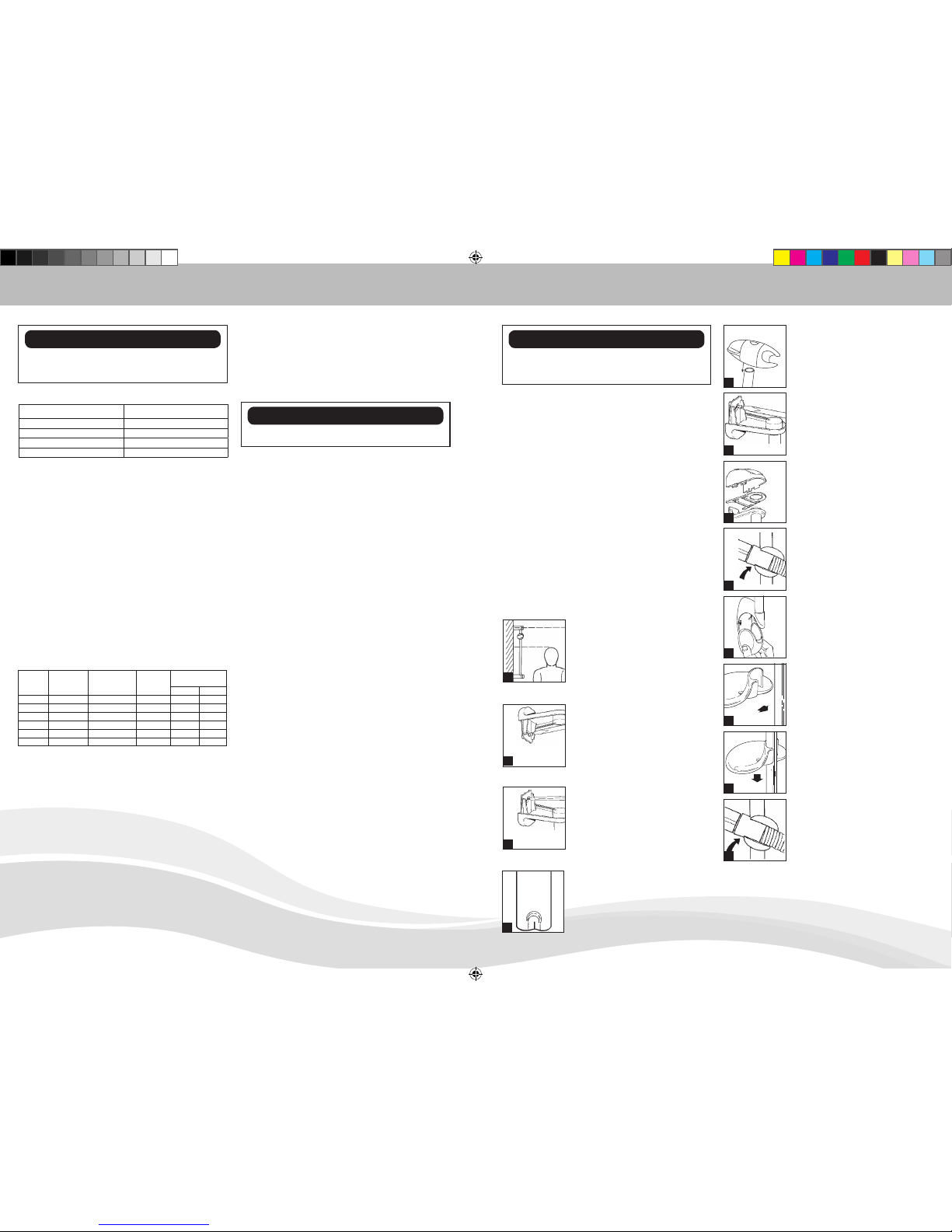
excess material from the
plain end of the rail.
5. The three components
that comprise the
Handset Height Adjuster
assembly are produced
with alphabetical ‘A’s and
‘B’s moulded into the
end section of each part.
Simply just match the letter
identification of each part
with the central piece i.e.
‘A’ to ‘A’ and ‘B’ to ‘B’ for
correct assembly.
6. With the shower head
height adjuster lever set a
3 o’clock and the shower
head holder in the upright
position, slide the assembly
onto the rail. Tighten to the
rail by turning the lever.
7. To lock the Handset Height
Adjuster at your chosen
position on the rail. Turn the
lever up right. This action
is also used for holding the
shower head at the angle
required.
8. Re-assemble the rail and
screw the upper mounting
bracket in place.
9. Slide the end cap onto the
mounting brackets.
10. Snap the soap dish onto
the rail below the holder
assembly.
11. Slide soap dish down the
rail to required position.
12. Firmly attach flexible hose
to the shower head making
sure sealing washer is in
place. NOTE: the adjustable
slider grips the conical end
of the hose, not the handle
of the shower head.
4
8
9
10
11
12
2
1
1. Establish position for the
riser rail, and mark the wall
for the lower mounting
bracket.Make allowances
for the tallest person likely
to use the shower regularly.
2. Use a No 10/5.5mm
masonry drill to make a
hole 35mm deep, and
fit the wall plug. (NB
some wall constructions
may require the use of
alternative types of wall
fixings). Screw the lower
bracket base to the wall.
3. Locate the crimped end of
the riser rail (Fig. 4) into the
mounting bracket, then fit
the upper bracket. Ensure
the rail is vertical, then mark
the wall for the fixing.
4. The crimped end of the riser
rail. NOTE: If it is necessary
to shorten the rail, use a
junior hacksaw to cut the
3
Maintenance: Clean regularly with a non-
abrasive liquid bathroom cleaner.
The incoming cable should be hidden.
Connect the live cable to the terminal
marked L.
Connect the neutral cable to the terminal
marked N.
Connect the earth cable to the terminal
marked Eon the back plate.
IMPORTANT
Ensure that the terminal block screws are
fully tightened and that no cable insulation is
trapped under screws.
Ensure the cable clamp is used to secure the
cable.
SECTION 7
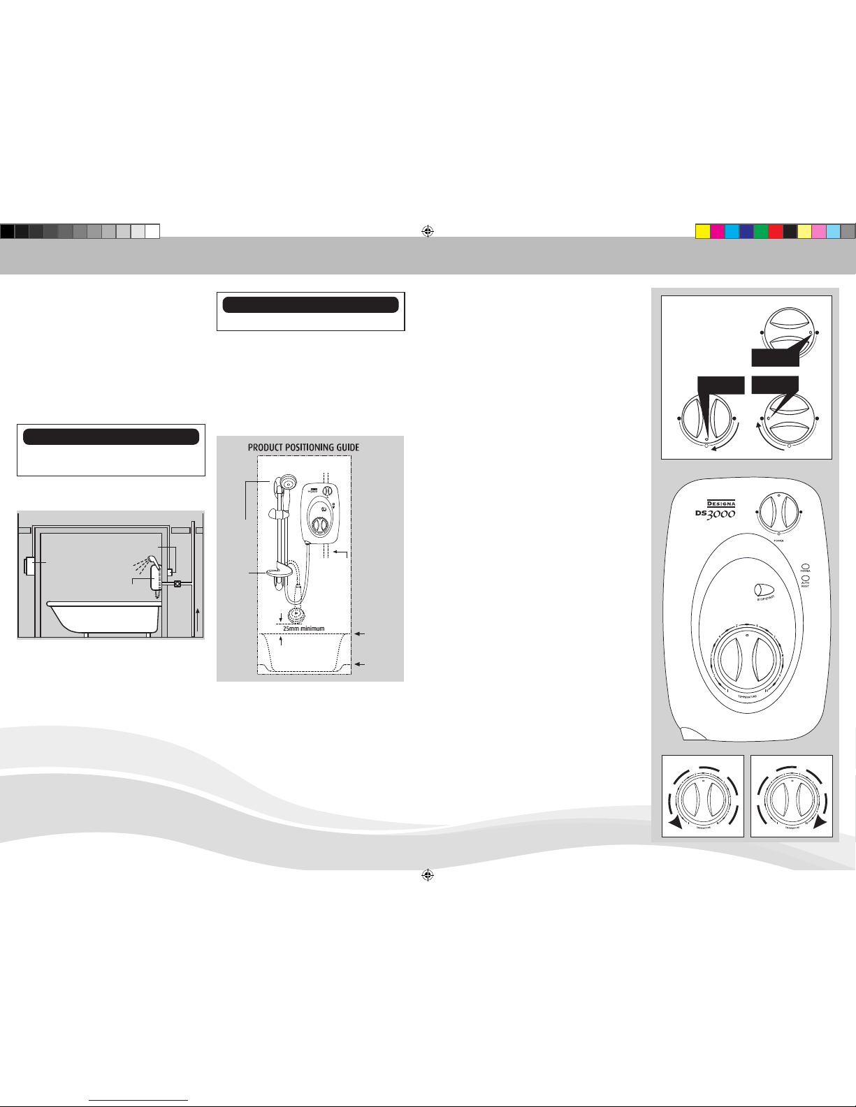
Fitting the cover into position
NOTE: It is necessary to align the ‘D’ flat on
the reverse side of the Power Selector and
Temperature knobs with their opposite control
spindles before the cover is located.
Secure the cover with the two fixing screws
provided.
IMPORTANT: Turn the flow control knob
anti clockwise until the valve is fully open
before switching on the unit. This will
ensure a fast fill up of the unit when the
shower is first switched on.
Switch on the power to the shower unit at the
consumer unit and the double pole switch. At
this stage the power selector knob should be
on the COLD position (Solid Blue Symbol).
Remove the shower head from the flexible
hose and point to waste.
Turn the top power selector knob to the
COLD (Solid Blue Symbol) setting.
Start the shower unit by pressing the STOP/
START button. Let the water flow through the
shower unit to release any air which may be in
the system and fill the shower unit with water.
IMPORTANT: The shower unit must be full
of water before heat settings are used.
Switch the shower unit OFF by pressing the
STOP/START button.
Re-fit the shower head to the flexible hose.
Your shower is now ready to use. We recommend
that you allow your shower to reach a stable
temperature before you commence showering.
SECTION 6
Electrical connection
Warning! This appliance must be earthed
The shower unit must be permanently connected
to the electricity supply, direct from the consumer
unit via a double pole linked switch with a
minimum contact gap of 3mm. The switch must
be readily accessible and clearly identifiable and
out of reach of a person using a fixed bath or
shower tray, unless the switch is cord operated.
The wiring must be connected to the switch
without the use of a plug or socket outlet.
The cable size required is determined by the kW
rating of the shower and the distance between
the shower and the consumer unit. The table
below will help you choose the correct cable
for your installation, but it will depend upon the
precise circumstances of the installation. If you
are in any doubt consult an electrician.
KW
RATING
NOMINAL
AT 240v
MIN. RATING
OF ISOLATING
SWITCH
FUSE
RATING
MAX CABLE
RUN
6mm 10m
7.0 29.10 amps 30 amps 30 amps 29m 48m
7.5 31.25 amps 40 amps 40 amps 27m 44m
8.0 33.33 amps 40 amps 40 amps 25m 42m
8.5 35.41amps 40 amps 40 amps 23m 38m
9.5 39.58 amps 40 amps 40 amps 21m 32m
10.5 43.75 amps 45 amps 45 amps 18m 30m
The earth continuity conductor of the electrical
installation must be effectively connected to all
exposed metal parts of other appliances and
services in the room in which the shower unit is
installed to confirm with IEE regulations.
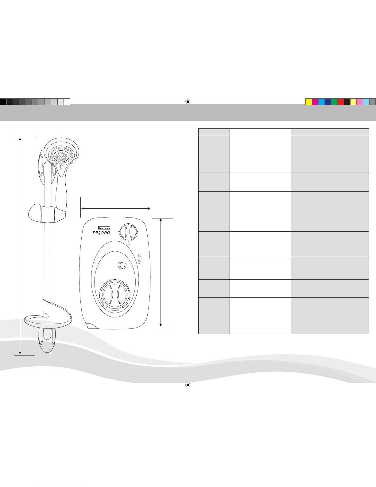
NOMINAL POWER RATING AT 240V NOMINAL POWER RATING AT 230V
7.5kW - (32A MCB rating) 6.9kW - (32A MCB rating)
8.5kW - (40A MCB rating) 6.9kW - (32A MCB rating)
9.5kW - (40A MCB rating) 8.7kW - (40A MCB rating)
10.5kW - (45A MCB rating) 9.6kW - (45A MCB rating)
ELECTRICAL SPECIFICATIONS
ds3000 12pg booklet_2009_pag.ind8-9 8-9 30/9/09 9:45:10 am
Table of contents
Popular Plumbing Product manuals by other brands

Hans Grohe
Hans Grohe Axor Talis S 72412000 Instructions for use/assembly instructions

Grohe
Grohe EUROECO COSMOPOLITAN E 36 273 manual

baliv
baliv WT-5061 Series manual

Moen
Moen One-Handle Lavatory Faucet user manual

Kohler
Kohler Sterling 225C7 Installation and care guide

KWC
KWC GLX2020 Installation and operating instructions

Spectrum Brands
Spectrum Brands Pfister McAllen R89-5MCA Series Quick installation guide

baliv
baliv KI-1360 manual

GATTONI
GATTONI H2OMIX1000 1043 Installation and assembly

sentlotec
sentlotec LAVA Assembly instructions

KWC
KWC F5 ACXM1002 Installation and operating instructions

Kallista
Kallista ONE P24476 installation instructions