DesignTech Smart Alarm 20620 User manual

Page 1
20620
Smart Alarm®
V 7.1
Remote Car Alarm
Model 20620
Installation Manual
For Use On Vehicles With 12 Volt (Negative Ground) Electrical Systems
7955 Cameron Brown Court • Springfield, Virginia 22153 • USA
Tel: (703) 866-2000 • Fax: (703) 866-2001
Page 2 20620 Page 3
20620
Transmitter
Congratulations on your purchase of our Smart Alarm®, the first car
alarm designed to protect both You and Your Car.
Smart Alarm®Protects Your Car:
The shock sensor built into the Smart Alarm®sounds the siren and
flashes your car's headlights if your vehicle is struck or jolted.
Current sensor sounds siren and flashes headlights if someone tries to
start your car while the car alarm is armed or if a light is triggered by
opening the doors, trunk or hood.
Smart Alarm®Protects You:
Sounds a panic alarm, which you activate from up to 400 feet away, to
call for help or scare away troublemakers.
The Carfinder®feature helps you locate your vehicle quickly in a large
parking lot by flashing the lights and chirping the siren to tell you its
location.
Turns on your headlights by remote control for 30 seconds to light
your way to or from your vehicle.
Stops carjacking by creating a delayed panic alarm 1 minute after the
vehicle is taken. The alarm will sound and flash your car's lights for 50
seconds after your car has been turned off.
Instructions for
Smart Alarm®
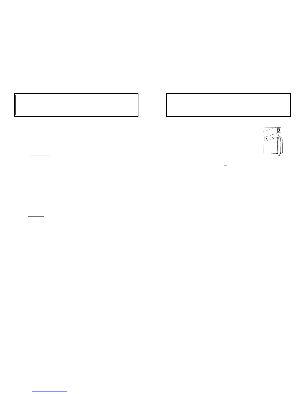
Your Smart Alarm®Transmitter
Operates As Follows:
Press once for 1 second: Arm alarm / Siren chirps
once or
Lights flash once (Lights will flash if siren is
silent)
Press again for 1 second: Disarm alarm / Siren chirps twice or
Lights flash twice (Lights will flash if siren is
silent)
Note:ifalarmhasbeentriggered,youwillhear
4 chirps during disarm)
Button Two:
Press for 1 second: Carfinder®(siren sounds for 2 seconds and
lights come on for 2 seconds)
Hold down for 3-4 seconds: Ifvehicleisnotrunning: Panic Alarm (flashing
lights and siren)
If vehicle is running: Anti-
carjacking (alarm activates 1 minute later and
stays on until 55 seconds after the ignition is
finally turned off)
Button Three:
Press once (1 second): Turn headlights on for 30 seconds
If you press ButtonThreejust before pressing Button One, then the alarm
will operate silently (i.e. with no siren chirp). Instead, your car lights will
flash once to confirm arming and twice to confirm disarming.
The Smart Alarm®is fully user programmable from the remote transmitter
for choosing shock sensitivity and your choice of 8 different siren sounds.
The light on the transmitter will turn Green when button
#1is pressed, Red with button #2 and Yellow with button
#3 when it is transmitting.

Page 4 20620 Page 5
20620
Installation Instructions
Never install this product with the engine running and be certain
to keep the alarm's wires away from moving parts.
Step 1 Mounting the Unit
Mount the
Warning: When working around the car battery, never allow any metal
toolsto short acrossthe two battery terminals orfrom+12Volts to ground!
Contents:
1 Smart Alarm®siren module
1 3-Button transmitter (comes with long-life lithium batteries)
2 Blue Scotch-Lock wire connectors
4 Cable ties (4" long) for wires
1 Spare blue 15 amp fuse
2 Screws & lockwashers for mounting bracket
2 "Warning: Protected by DesignTech" window decals
Wire Functions:
RED +12 Volts ("+" positive)
BLACK Ground ("-" negative)
YELLOW Headlights Control
GREEN Electric Fan Sense (not always required)
BLACK W/ CLEAR END Coaxial Antenna Wire
Tools Needed:
•Drill
•1/8" Drill Bit (for drilling holes for bracket)
•Pliers
•Phillips Head Screwdriver
•Small Adjustable (crescent) Wrench
Before You Get Started
Page 6 20620 Page 7
20620
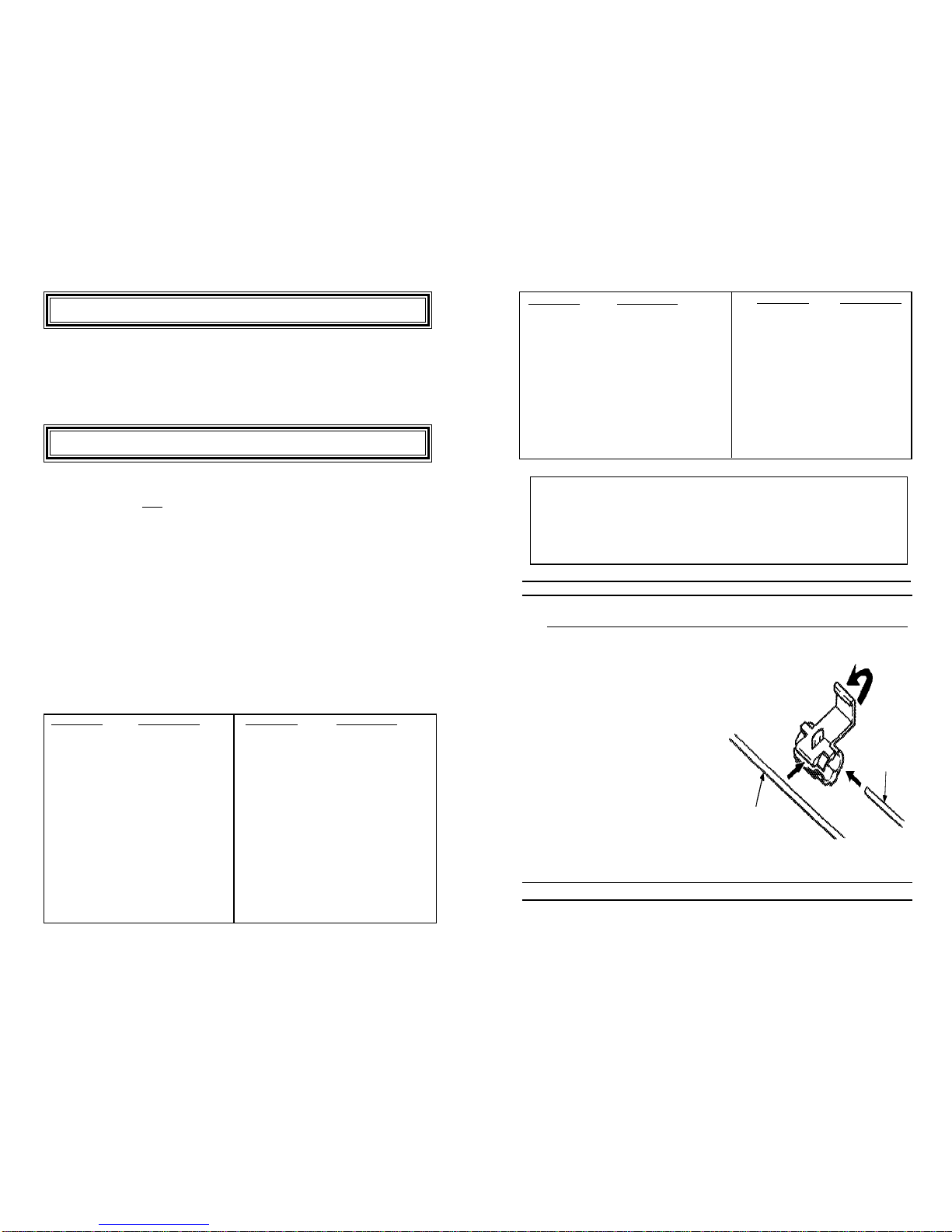
How To Use The Scotch-Lock Connector
The diagram below shows how to use the blue Scotch-Lock wire con-
nectors to tap into the desired
wires.
1) Slip the connector over the
wire you want to attach to.
2) Push the Smart Alarm's®
wire (unstripped) as far as
it will go into the open end
of the connector.
3) Use pliers to press the metal
blade into the wires.
4) Close the plastic cover over
until it clicks.
Yellow
Wire
Your Car's
Headlight Wire
MAKE OF CAR LOWBEAM WIRE
NISSAN
MAXIMA RED/YELLOW
TRUCK/PATHFINDER RED/BLUE
SENTRA/NX2000 RED/YELLOW
240 SX RED/BLACK
300 ZX RED/BLACK
STANZA RED/YELLOW
PORSCHE
PORSCHE GREEN/YELLOW
SAAB
SAAB 9000 GRAY
SAAB 900 GRAY
SUBURU
SUBURU RED/YELLOW
SUZUKI
SAMIRAI RED/WHITE
SIDEKICK RED
SWIFT RED
MAKE OF CAR LOWBEAM WIRE
TOYOTA
TOYOTA CELICA GREEN
LANDCRUISER RED/BLUE
CAMRY RED/BLUE
TRUCK/4-RUN RED/GREEN
PREVIA RED/YELLOW
SUPRA GREEN
MR2 GREEN
CRESSIDA RED/YELLOW
COROLLA RED/YELLOW
VOLVO
240 BLUE
740/760 GREEN
940/960 GREEN
VOLKSWAGEN
MOST VOLKSWAGEN YEL/BLK
Key: LFT=left side of car; RT=right side of car. When different
colors are listed for the two sides of a vehicle, you only need to con-
nect to one of those wires. Where two colors are listed with a slash "/
" seperating them, it is a striped wire (e.g. RED/BLK is a RED wire
with a BLACK stripe).
MAKE OF CAR LOWBEAM WIRE
HYUNDAI
SONATA RED/WHITE
SCOUPE RED/WHITE
EXCEL YELLOW/BLUE
INFINITY
Q-45 ORANGE
G-20 RED/BLUE
M-30 ORANGE/BLUE
ISUZU
RODEO RED/GREEN
PICK-UP RED/BLUE
AMIGO RED/WHITE
IMPULSE RED/GREEN
TROOPER RED/YELLOW
LEXUS
LS-400 RED/WHITE
ES-250 RED/YELLOW
MAZDA
MOST MAZDA RED/BLACK
323/PROTEGE RED
MERCEDES
MERCEDES LFT HD BLK/YEL, RT HD
YEL
MAKE OF CAR LOWBEAM WIRE
GENERAL MOTORS
MOST GM TAN
SATURN TEST
GEO RED/WH
FORD
MOST FORD RED/BLACK
CHRYSLER
MOST CHRYSLER PURPLE/RED
INTREPID RED/WHITE
LASER/TALON RED/WHITE
CHRYS TRUCKS PURPLE
JEEP GREEN
ACURA
MOST ACURA RED/YELOW
AUDI
MOST AUDI LFT BLACK/RT YELLOW
BMW
3 SERIES LFT YEL-WHI/RT YEL-BLU
5 SERIES LFT YEL-GRN/ RT YEL-BLU
7 SERIES LFT YEL-GRN/ RT YEL-BLU
HONDA
MOST HONDA RED/YELOW
PRELUDE POP-UP USE PARK RED/BLK
Step 3 +12 Volts Red Wire
Connect the RED wire with its in-line fuseholder and 15 amp fuse to
the +12 volt ("+") side of the battery terminal. Using our "U" shaped
connecter, simply unscrew the battery terminal connector bolt a few
turns, insert the "U" connector, and re-tighten the bolt.
Step 4 Headlights Yellow Wire
Connect the YELLOW wire to the low-beam headlight wire coming
off the back of one of the headlights. Use the charts below as a guide-
line to help determine which wire is the correct low-beam wire. (For
cars with 4 head lamps in a line from right to left, the low beam lamp is
always the outer lamp. When the vehicle has 2 lamps, one on top of
the other, the low beam is always the top lamp).
Rule of Thumb: For most two lamp systems and circular four lamp
systems, the YELLOW wire from the Smart Alarm®connects to the
wire coming from the middle connector on the back of the (lowbeam)
headlight. On most rectangular four lamp systems, the YELLOW wire
from the Smart Alarm®connects to the wire coming from the left con-
nector (as seen from inside the hood area) on the back of the (lowbeam)
headlight. If the chart indicates otherwise for your car, go with the
chart! Note: the chart is only a guide and does not cover all makes and years.
Page 8 20620 Page 9
20620
2) Within 10 seconds of the first step, press button #2 (red) on your
transmitter until the receiver chirps once (usually hold button for about
5 seconds), signifying that it has learned the code. If you have addi-
tional transmitters, teach the receiver these by pressing the second
transmitter's red button within 5 seconds of the receiver learning the
first transmitter code.
3) After programming the last transmitter, wait 5 seconds for the 3 exit
chirps. Your Smart Alarm®is now ready to use! Follow these steps
again to relearn new transmitters, if necessary, in the future.
Press these at the
same time, for 2-3
seconds, to enter
programming mode
Step 5 Electric Fan Sense Green Wire
This wire is only necessary in vehicles with electric cooling fans that
stay on after you shut off the car. To tell if you need to hook up this
wire: On a hot day (or after your engine has been running for a long
time) after you shut off your car, your fan will keep running for a few
minutes to cool down your engine. If you have this type of fan, then
hook the GREEN wire up to the wire that supplies +12 volts to the fan
motor. Usually, two wires go to the back of the fan motor. Test the two
wires with a voltage tester and tap into the wire (with a Scotch-Lock
connector) which shows +12 Volts with the fan turned on. This will
disable the current sensing portion of the alarm when the fan is on.
Step 6 Antenna Wire
Route the Antenna Wire (thick black with the clear plastic end) to the
front of the grille of the car. The last clear 8 inch length is the actual
antenna and must be exposed. Secure the clear end, using 2 cable ties,
to the grille. The more exposed the antenna, the better the range. No
antennacable should remain coiled up - this willgreatly decrease range.
Step 7 Quick Test
At this point your alarm should be working. Before going on, test it
by pressing the middle (red) button for 1 second to get the CarFinder™
Feature. If this feature is working, your Smart Alarm®should be to-
tally functional. If you get no response from this test, go on to step 8.
If the test works, go straight to step 9.
Step 8 Learning the Transmitter Code
Your Smart Alarm®comes with the transmitter precoded to the re-
ceiver. If your alarm does not respond to the transmitter, do the fol-
lowing:
1) Pull out the 15 amp fuse for a few seconds, then replace it. The siren
will sound for 1 second confirming the unit is again receiving power.
Step 9 Choosing Shock Sensitivity
You can program the shock sensitivity level of your Smart Alarm®to
maximize sensitivity while reducing false alarms.
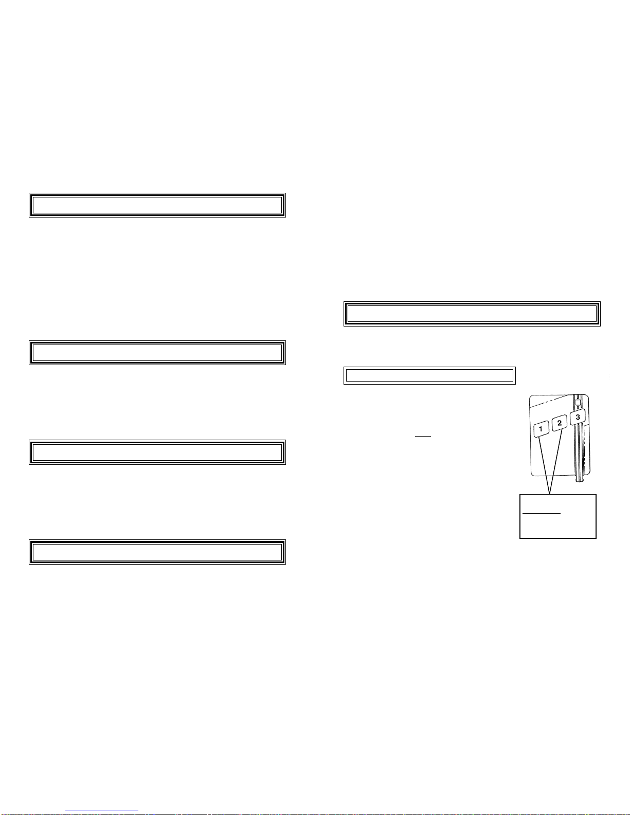
TO ENTER PROGRAMMING MODE:
1) Press buttons one and two simultaneously
for 2-3 seconds. You will hear the alarm for
one second and then 3 rapid chirps; let go of
the buttons only after you have heard the con-
firmation chirps or you will not enter the pro-
gramming mode! Once you have heard the
confirmation chirps you are ready to program
your shock sensitivity.
2) Press button #1 (green) to enter the shock
sensitivity selection mode. By pressing the
GREEN button again you can scroll through
the different levels of shock. There are 8 lev-
els of shock and 8 corresponding tones. The
higher the pitch of the tone heard from the
siren, the more sensitive the alarm is to shock. At any time, you can
stop and try out the sensitivity of the setting by hitting your car with
your fist on the body or windshield to see if that level of impact sets off
the alarm (remember, you are simulating the shock which the car would
feel if someone were breaking glass to enter your vehicle). The siren
will sound for 1-2 seconds if you have hit the car hard enough to set off
the alarm.
Page 10 20620 Page 11
20620
Step 11 Try Out The Alarm
Now everything is complete and it is time to try out the system.
•Press button #3 (yellow) and the headlightsshould come on. They
will turn off in 30 seconds -- or you can turn them off by pressing
the YELLOW button again.
•Press button #2 (red) for 1-2 seconds to get the CarFinder®fea-
ture. The siren will sound for 1-2 seconds and the lights will flash.
•Press and hold button #2 (red) for 3 seconds to get the Panicmode.
The alarm will sound and the lights will flash for 30 seconds. You
can turn off the alarm by pressing the RED button again.
•With the car running, press and hold button #2 (red) for 3 seconds
to try the Carjacking mode. The alarm will wait one minute and
then go off until 55 seconds after the car is turned off.
•Press button #1 (green) for 1 second. You will hear one chirp
signifying that the alarm is now armed. Open the car door and the
current draw caused by the interior dome light coming on will set
off the car alarm. Hold down button #1 (green) for 2 seconds to
turn off the alarm. Push the left button again to re-arm the system.
This time, hit the vehicle with your fist to simulate a thief breaking
into your car - and test out the shock sensor mode. Again, turn off
the alarm by pressing button #2 (red) for 2 seconds.
•Pleasenote that any radio frequency type product is subject tomany
conditions including interference from other products. "Line-of-
sight" range should be up to 400 feet in front of the vehicle, but
will be less from different angles of the vehicle and under other
conditions (such as being inside a building or other structure, or
being in a high radio interference area).
3) When you have settled on a proper sensitivity level, simply press
button #3 (yellow) to exit programming mode and save this sensitivity
level. If you don't press any buttons for 5 seconds, you will automati-
cally exit the programming mode.
Step 10 Choose Siren Sound
You can personalize your alarm's sound by selecting one of eight dif-
ferent siren sounds..
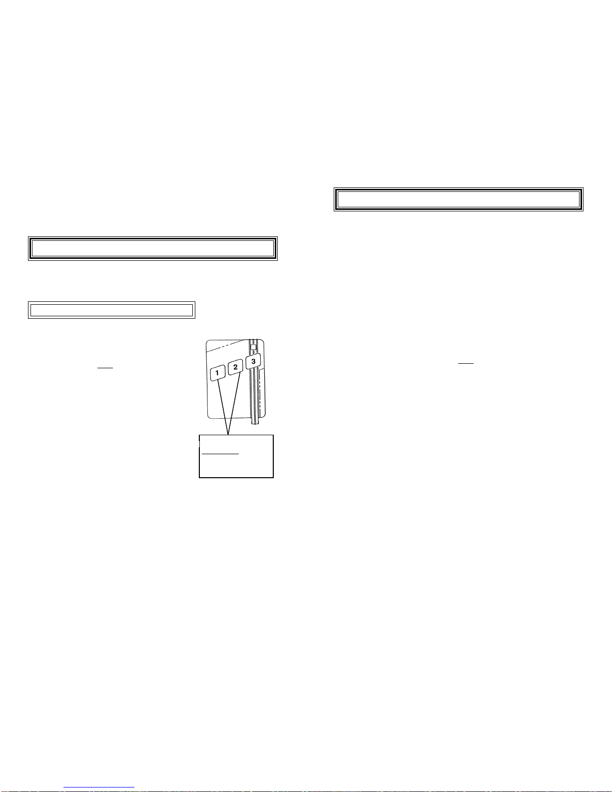
TO ENTER PROGRAMMING MODE:
1) Press buttons one and two simultaneously
for 2-3 seconds. You will hear the alarm for
one second and then 3 rapid chirps; let go of
the buttons only after you have heard the con-
firmation chirps or you will not enter the pro-
gramming mode! Once you have heard the
confirmation chirps you are ready to program
your shock sensitivity or your siren sounds.
2) Press button #2 (red) to enter the siren
sound selection mode. By pressing the RED
button in the siren sound selection mode, you
can scroll through the various siren sounds
until you find one you like (you will hear 2
seconds of the selected siren sound each time
you scroll to a sound).
3) When you have settled on a favorite sound,
simply press button #3 (yellow) to exit pro-
gramming mode and save the last sound
played. If you don't press any buttons for 5
seconds, you will automatically exit the pro-
gramming mode.
Press these at the
same time, for 2-3
seconds, to enter
programming mode

Page 12 20620 Page 13
20620
Accessories
DesignTech's Universal Remote Control Garage Door Opener system makes a
great add-on to the Smart Alarm®. The Garage Door Opener can learn your
transmitter's code, allowing you to open your garage using the Smart Alarm®
remote which is already on your keychain. For greater convenience you can
add up to 4 remote transmitters so all the drivers in your family can have a
long-range, convenient remote control garage door opener.
This is a perfect add-on for those who:
•Can't find a replacement for their old garage door opener remote
•Want longer range out of their remote (this unit has up to 300 ft. range).
•Want to get rid of that clunky old remote control and replace it with a
miniature, lightweight remote transmitter.
•Needmore transmitters than came with their original garage dooropener
system.
Note that the Universal Remote Control Garage Door Opener does not dis-
place your existing garage door controller. Rather, this system simply piggy-
backs your existing system, enabling you to use both your old and your new
transmitters to control your garage. Please call your local DesignTech sales
outlet or call DesignTech directly at (703) 866-2000 for more information on
the product or for ordering.
Remote Control Garage Door Opener Module Model 30021 $49.95
Extra one button remote transmitter Model 20051 $44.95
Trouble Shooting
Nothing Happens At All: Be sure that the fuse is securely in the Red
wire coming from the siren body and that power is reaching the unit
(test by using a voltage tester on the Red wire to find +12 Volts). Also,
review transmitter learning. Refer to steps 2, 3, and 7.
The Fuse Blows Every Time: Disconnect the Yellow wire and try
again. If the fuse doesn't blow with the Yellow wire disconnected,
then the only problem is that you are not on the low beam wire coming
off the back of the head lamp. Refer to step 4.
If The Headlights Don't Work: Using a Voltmeter or test light, make
sure the Yellow wire is Scotch-Locked to the low-beam headlight wire
that is "hot" (+12 volts) when the low beams are on. Refer to step 4.
General Maintenance
This product should provide years of service.
Remember to replace the batteries in the transmitter every 4-5 years.
The battery type is CR2025 lithium. Most camera stores carry these or
they can be ordered from DesignTech.
Forany questions concerning usage or installation of this product, please
call 1-800-337-4468.
PART____________________________ Part # Cost__
Additional batteries for transmitter (set of 2) 20059 $7.95
Extra 3 Button Transmitter 25561 $49.95
Prices are in U.S. dollars and include shipping and handling.
7955 Cameron Brown Court • Springfield, Virginia 22153 •
USA
Tel: (703) 866-2000 • Fax: (703) 866-2001

Page 14 20620
LIMITED WARRANTY
DesignTech International, Inc. Warrants to the original consumer/purchaser that this product shall be
free of defects in material and workmanship under normal use and circumstances for a period of two
(2) years from the date of original purchase for use. When the original consumer/purchaser returns
the product to DesignTech International Inc., 7955 Cameron Brown Court, Springfield, Virginia 22153,
USA within the warranty period, and if the product is defective DesignTech International, Inc. will at
its option repair or replace such.
This warranty shall constitute the sole liability of DesignTech International, Inc. concerning the prod-
uct. DesignTech International, Inc. expressly disclaims all other warranties INCLUDING, WITHOUT
LIMITATION, THE WARRANTIES OF MERCHANT ABILITY AND FITNESS FOR A PARTICU-
LAR PURPOSE. NO PERSON, FIRM , OR CORPORATION IS AUTHORIZED TO ASSUME FOR
DESIGNTECH INTERNATIONAL, INC. ANY OTHER LIABILITY IN CONNECTION WITH THE
SALE AND USE OF THE PRODUCT. DesignTech International, Inc. and agents and distributors
will bear no liability whatsoever for incidental or consequential damages or charges of any kind.
Some states do not allow the exclusion or limitation of incidental or consequential damages, so the
above disclaimer regarding incidental or consequential damages may not apply to you.
This warranty shall be effective only if the registration card is fully completed and mailed with proof
of purchase to: DesignTech International, Inc., 7955 Cameron Brown Court, Springfield, Virginia
22153, USA within ten (10) days after date of purchase.
This warranty is void if the product or has been damaged or tampered with or if the product or any
such parts have been opened. In all cases of damage during shipment, a claim must be filed with the
shipping carrier and not with DesignTech International, Inc.
This warranty gives you specific legal rights; you may also have other rights which vary from state to
state.
OUT OF WARRANTY REPAIRS
DesignTech International, Inc. will at its option either (1) replace this product with a functionally
similar (but not necessarily visually identical) refurbished product or (2) repair the original product
and return it to the original consumer/purchaser C.O.D. covering all reasonable repair or replacement
charges if the product is returned prepaid to DesignTech International, Inc., 7955 Cameron Brown
Court, Springfield, VIRGINIA 22153, USA, after the two year warranty period has expired.
__________________________________________________________________________
This registration card must be returned within ten (10) days of purchase.
NAME__________________________________________________User's Age___________
ADDRESS________________________________________________________________
________________________________________________________________________
City State Zip
PLACE OF PURCHASE_________________________DATE OF PURHASE____________
Product Purchased: SMART ALARM®#20620
Purchased for : __________YOURSELF _________SPOUSE
__________OTHER FAMILY MEMBER _________FRIEND
Who installed this alarm?
Where did you learn about this product?__________________________________________
Vehicle Make:__________________Vehicle Model:________________Year:____________
___________Please send me FREE information on other innovative DesignTech products.
DesignTech International, Inc.
7955 Cameron Brown Court, Springfield, Virginia 22153, USA
Tel: (703) 866-2000 Fax: (703)866-2001
Name Location
Table of contents
Other DesignTech Car Alarm manuals

Popular Car Alarm manuals by other brands


SLI
SLI ENFORCER 100LB owner's manual

DEI
DEI 4500 owner's guide

Directed Electronics
Directed Electronics AM2 owner's guide

Federal Signal Corporation
Federal Signal Corporation Pathfinder Siren Series Installation and maintenance manual

Scytek electronic
Scytek electronic Vectra X3 product manual

Directed Electronics
Directed Electronics VIPER 5701 owner's guide