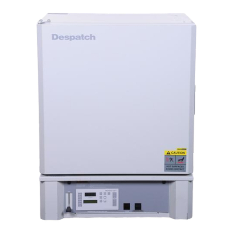
Despatch LBB 1-23 User manual

LBB Series Oven Owner’s Manual PREFACE
Version 20
LBB SERIES OVEN
OWNER’S MANUAL
C-188
PN 336979
VERSION 20
4/2018

PREFACE LBB Series Oven Owner’s Manual
2 Version20
Revision History
Revision
Date
Author
Description
C
Updated electrical drawings in DRAWINGS AND
SPARE PARTS LISTS section.
D
Corrections.
E
Correction, page 19, set-up parameter table
F
Parts lists corrections in DRAWINGS AND SPARE
PARTS LISTS section
G
Corrections to SPECIFICATIONS section, addition of
options and features in APPENDIX
H
Change Product Warranty page
I
Update drawings and High Limit information
J
Parts lists corrections in DRAWING AND SPARE
PARTS LISTS section. Corrected Despatch address.
K
Parts lists corrections in DRAWING AND SPARE
PARTS LISTS section
L
Updated warranty
12
3/2011
Livingston
Revise format
13
9/2011
Livingston
Additional parts tables
14
6/2012
Livingston
Update for Protocol 3
15
8/2012
Livingston
Corrections—Power Section.
15
7/2013
Livingston
Corrections—Minor correction to header.
16
8/2013
Meyer
Correction to LBB2-12 spare parts list
17
2/2014
Livingston
Minor copy changes. Remove LBB1-43 references.
17.1
4/2014
Livingston
Revised schematics added plus various small changes.
18
5/2014
E. Anderson
R3 REV -2 modifications
19
4/2016
E. Anderson
Misc clean-up and formatting
20
4/19/18
T Weller
Misc. updates

LBB Series Oven Owner’s Manual PREFACE
Version 20

PREFACE LBB Series Oven Owner’s Manual
4 Version20

LBB Series Oven Owner’s Manual PREFACE
Version 20
Table of Contents
1. About This Manual............................................................................................................. 8
1.1. Important User Information..................................................................................... 8
1.2. Manufacturer & Service .......................................................................................... 9
1.3. Organization of this Manual.................................................................................... 9
1.4. Conventions........................................................................................................... 10
1.5. Specifications ........................................................................................................ 11
1.5.1. Dimensions........................................................................................................ 11
1.5.2. Capacities .......................................................................................................... 12
1.5.3. Power................................................................................................................. 13
1.5.4. Temperature....................................................................................................... 14
1.5.5. LBB Series Oven Operating Conditions ........................................................... 14
2. Safety................................................................................................................................ 15
2.1. Safety Information................................................................................................. 15
2.1.1. Lockout.............................................................................................................. 15
2.1.1.1. Lockout Requirements................................................................................... 15
2.1.1.2. Lockout Procedure......................................................................................... 15
2.2. Provisions for Lifting and Carrying....................................................................... 16
2.3. Maintenance .......................................................................................................... 16
2.4. Electrical Power..................................................................................................... 16
2.5. Fire......................................................................................................................... 17
2.6. Equipment Lockout Requirements........................................................................ 17
2.6.1. Emergency Stop................................................................................................. 18
2.7. Disconnecting Devices.......................................................................................... 18
2.7.1. Power Requirements.......................................................................................... 18
2.7.2. Disconnecting Hard-Wired Units...................................................................... 18
2.7.3. Disconnecting Corded Units.............................................................................. 19
2.7.4. Disconnecting Units with (Optional) Disconnect Switch.................................. 19
3. Theory of Operation......................................................................................................... 20
3.1. The LBB Series Oven............................................................................................ 20
3.1.1. Oven Theory...................................................................................................... 21
3.2. Control Systems..................................................................................................... 21
3.2.1. Primary Control Instrument............................................................................... 21
3.2.2. High Limit Instrument....................................................................................... 22
3.2.2.1. Product High Limit Instrument...................................................................... 23
3.2.2.2. Oven High Limit Instrument ......................................................................... 23
3.3. The Protocol 3 Controller (Optional) .................................................................... 23
4. Assembly & Setup............................................................................................................ 24
4.1. Unpack & Inspect the LBB Series Oven............................................................... 24
4.1.1. If Damaged During Shipping ............................................................................ 24
4.2. Set-up the LBB Series Oven.................................................................................. 24
4.2.1. Select Oven Location/Operating Environment.................................................. 24
4.2.2. Set-up Procedure ............................................................................................... 25
4.2.3. Wiring & Power Connections ........................................................................... 25
5. Operation.......................................................................................................................... 28
5.1. Load Oven............................................................................................................. 28
5.2. Pre-Startup Checklist............................................................................................. 29
5.3. Operating Procedure—Standard Control Instrument ............................................ 30
5.3.1. Start Oven.......................................................................................................... 30
5.4. Working with the Control Instrument ................................................................... 32
5.4.1. Change Setpoint................................................................................................. 32

PREFACE LBB Series Oven Owner’s Manual
6 Version20
5.4.2. Control Instrument Parameter Programming Mode .......................................... 33
5.4.2.1. Entering Control Instrument Set-up and Configuration Mode...................... 33
5.4.2.2. Control Instrument Operating Mode Notes................................................... 34
5.4.3. Change Control Instrument Display from Centigrade to Fahrenheit................. 35
5.4.4. Oven Zone Calibration...................................................................................... 36
5.4.5. Set the High Limit............................................................................................. 37
5.4.5.1. Change the High Limit Instrument Setpoint.................................................. 37
5.4.6. High Limit Instrument Parameter Setup Mode ................................................. 37
5.4.7. High Limit Instrument Setup Parameters.......................................................... 38
5.4.8. Change High Limit instrument Display from Centigrade to Fahrenheit.......... 39
5.5. Working with Optional Protocol 3 Controller Operating Modes.......................... 39
6. Maintenance ..................................................................................................................... 40
6.1. Checklist................................................................................................................ 40
6.2. Lubrication ............................................................................................................ 41
6.3. Cleaning and Decontamination ............................................................................. 41
6.3.1. Cleaning the LBB Series Oven.......................................................................... 41
6.3.2. Decontaminating the LBB Series Oven............................................................. 42
6.4. Routine Tests......................................................................................................... 42
6.4.1. Test Control Instrument..................................................................................... 43
6.4.2. Test High Limit Instrument............................................................................... 43
6.5. Replacement Parts................................................................................................. 44
6.5.1. Replace the Control Instrument......................................................................... 45
6.5.2. Replace High Limit Instrument......................................................................... 48
6.5.3. Replace (Optional) Protocol 3 Controller.......................................................... 50
6.5.4. Replace Heater Unit .......................................................................................... 50
6.5.5. Replace Fan Motor ............................................................................................ 52
7. Troubleshooting................................................................................................................ 55
Table 7. Common Technical Issues and Remedies....................................................................... 55
7.1. DES2000 Control Parameters Check .................................................................... 56
7.2. Hi Limit L91 Hi-Limit Reset................................................................................. 58
8. Appendices....................................................................................................................... 59
8.1. Standard Products Warranty.................................................................................. 59
8.2. Optional Equipment............................................................................................... 60
8.2.1. Assemble Oven Stand........................................................................................ 60
8.2.2. End of Cycle (EOC) Timer Option.................................................................... 61
8.2.3. Operating the Timer .......................................................................................... 62
8.2.4. Parameter Default Settings................................................................................ 64
8.2.5. Timer Option with Audible and Visual Alarm.................................................. 64
8.2.6. High Alarm Limit Option.................................................................................. 64
8.3. Part Lists................................................................................................................ 65
8.4. Mechanical Drawing ............................................................................................. 65
8.5. Electrical Schematics............................................................................................. 65

LBB Series Oven Owner’s Manual PREFACE
Version 20
Figures
Figure 1. Disconnect Switch.......................................................................................................... 19
Figure 2. LBB Forced Convection Benchtop Oven. ..................................................................... 20
Figure 3. Uniflow Airflow through the LBB Oven....................................................................... 20
Figure 4. LBB Series Oven Primary Control Instrument.............................................................. 21
Figure 5. High Limit Instrument. .................................................................................................. 22
Figure 6. Protocol 3 Operator Interface......................................................................................... 23
Figure 7. LBB Series Oven Name Plate Example......................................................................... 26
Figure 8. LBB Series Oven with Top Removed............................................................................ 26
Figure 9. Wiring Access through Rear of Oven............................................................................ 27
Figure 10. Close-up of Connector Block....................................................................................... 27
Figure 11. LBB Series Oven Control Panel. ................................................................................. 31
Figure 12. Adjust Damper to Set Exhaust Vent by rotating the outer component........................ 31
Figure 13. Remove Control Panel to Access Control Instrument (using T20 Torx bit driver). .... 45
Figure 14. Providing easy access to the Control instrument. ........................................................ 46
Figure 15. Remove old Control and High Limit Instruments and Wiring (Rear View)................ 46
Figure 16. Prepare to remove control instrument by removing the mounting bracket.................. 47
Figure 17. Connections to Control Instrument.............................................................................. 47
Figure 18. High Limit Connector Block on Control Board........................................................... 48
Figure 19. Press and Hold Tabs to Remove High Limit Instrument............................................. 49
Figure 20. Connections to High Limit Instrument. ....................................................................... 49
Figure 21. Remove Screws to Remove Each Duct (using T15 Torx bit driver............................. 50
Figure 22. Heater element connections. ........................................................................................ 51
Figure 23. Typical Heating Element (Inset connections see Figure 22) ....................................... 52
Figure 24. Fan Motor Location. .................................................................................................... 53
Figure 25. Separate fan wheel from fan motor shaft..................................................................... 54
Figure 26. Optional LBB Oven Stand........................................................................................... 60
Figure 27. Timer Option Displays and Switches........................................................................... 61
Tables
Table 1. Operating/Environmental Conditions (For indoor use)................................................... 14
Table 2. Control Instrument Explanations..................................................................................... 22
Table 3. High Limit Instrument Explanations............................................................................... 22
Table 4. Control Instrument Set-up Parameters. ........................................................................... 33
Table 5. Control Instrument Configuration Parameters. ............................................................... 34
Table 6. High Limit instrument Setup Parameters........................................................................ 38
Table 7. Common Technical Issues and Remedies....................................................................... 55

ABOUT THIS MANUAL LBB Series Oven Owner’s Manual
8 Version20
1. About This Manual
1.1. Important User Information
Copyright © 2018 by Despatch Industries.
All rights reserved. No part of the contents of this manual may be reproduced, copied, or
transmitted in any form or by any means including graphic, electronic, or mechanical methods or
photocopying, recording, or information storage and retrieval systems without the written
permission of the publisher, unless it is for the purchaser's personal use.
Produced in the United States of America.
The information in this manual is subject to change without notice and does not represent a
commitment on the part of Despatch Industries. Despatch Industries does not assume any
responsibility for any errors that may appear in this manual.
In no event will Despatch Industries be liable for technical or editorial omissions made herein,
nor for direct, indirect, special, incidental, or consequential damages resulting from the use or
defect of this manual.
Values displayed on screens are examples only. Though
those values may be typical, contact Despatch Industries for
the final value.
Users of this equipment must comply with operating
procedures and training of operation personnel as required
by the Occupational Safety and Health Act (OSHA) of 1970,
Section 5 and relevant safety standards, as well as other
safety rules and regulations of state and local governments.
Refer to the relevant safety standards in OSHA and National
Fire Protection Association (NFPA), section 86 of 1990.

LBB Series Oven Owner’s Manual ABOUT THIS MANUAL
Version 20 9
Danger!
Only fully-trained and qualified personnel should setup and
maintain this equipment. Improper setup and operation of this
equipment could cause an explosion that may result in
equipment damage, personal injury or possible death.
The information in this document is not intended to cover all possible conditions and situations
that might occur. The end user must exercise caution and common sense when installing or
maintaining Despatch Industries products. If any questions or problems arise, call Despatch
Industries at 1-800-762-0110 or 1-952-469-5424.
1.2. Manufacturer & Service
The LBB Series oven is manufactured by Despatch Industries.
Despatch has specialized in thermal processing for over 100 years. Technical expertise gained
over those years helps provide innovative solutions to critical applications in vertical markets and
cutting edge technology worldwide. Despatch products are backed by a drive for long-term
customer satisfaction and a strong sense of responsibility. The worldwide network of factory-
trained Service Professionals is available to support your Despatch equipment. From full service
preventive maintenance to routine repair and certified calibration and uniformity, the Despatch
service network is positioned to respond to your business needs. Our service programs are
customized to meet your specific needs using our Advantage Service Assurance Program
(ASAP). For more information on ASAP, visit www.despatch.com.
Global Headquarters
Contact
Service & Technical
Support
Despatch Industries
8860 207th Street
Lakeville, MN 55044
USA
International/Main: 1-952-469-5424
US toll free: 1-800-726-0110
Fax: 1-952-469-4513
www.despatch.com
Service: 1-952-469-8230
US toll free: 1-800-473-7373
Service @despatch.com
1.3. Organization of this Manual
This owner’s manual contains the most comprehensive set of information for the Despatch LBB
Series ovens, including installation instructions, theory of operation, and operating instructions,
among other things.

ABOUT THIS MANUAL LBB Series Oven Owner’s Manual
10 Version20
Danger!
Failure to heed warnings in this instruction manual and on the
oven could result in personal injury, property damage or death.
1.4. Conventions
This icon signifies information that describes an unsafe
condition that may result in death, serious injury, or damage to
the equipment.
Danger!
Danger is the signal word used to indicate a hazardous
situation that, if not avoided, will result in death or severe
injury.
Warning!
Warning is the signal word used to indicate a hazardous
situation that, if not avoided, could result in death or severe
injury.
Caution!
Caution is the signal word used to indicate a hazardous
situation that, if not avoided, could result in moderate or minor
injury.
Notice
Notice is the signal word used to indicate a hazardous situation
that, if not avoided, could result in property damage.
This icon signifies important supplemental information.
LOG OUT
Bold, 10 point sans-serif typeface indicates a specific key or
button on screen to click.

LBB Series Oven Owner’s Manual ABOUT THIS MANUAL
Version 20 11
1.5. Specifications
1.5.1. Dimensions
LBB
Model
No.
Chamber Size
in (cm)
Capacity
feet3
(liters)
Overall Size
in (cm)
Shelves
Provided
on Shelf
Centers
in (cm)
Maximum
Number of
Shelf
Positions
Chamber
Doors
W0
D
H
W
D
H
1-23
18
(46)
18
(46)
12
(30)
2.3
(65)
24
(61)
26
(66)
26
(67)
2 on 2”
(5)
5
1
1-69
30
(76)
18
(46)
22
(56)
6.9
(195)
36
(92)
26
(65)
36
(92)
2 on 2”
(5)
10
2
2-12
30
(76)
20
(51)
35
(89)
12.1
(343)
36
(91)
28
(71)
51
(131)
2 on 2”
(5)
16
2
2-18
37
(94)
24
(61)
35
(89)
18
(510)
43
(109)
32
(81)
51
(130)
2 on 2”
(5)
16
2
2-27
37
(94)
37
(94)
35
(89)
27.7
(784)
43
(109)
45
(114)
51
(130)
2 on 2”
(5)
16
2
NOTE –refer to assembly drawing for exact dimensions
The LBB oven is not intended to process solvents or other volatile
or flammable materials. Oven exhaust is intended for cooling
purposes only.
Warning!
Do not place this oven in an environment harmful to electrical
components.
Placing this oven in an environment detrimental to electrical
components (for example, environments where carbon fibers, coal
dust or similar contaminants may be present) may result in
component failure.
Do not use liquids in the oven. Do not set product or liquids on top
of the oven. Liquids that may spill on the oven floor or top of oven
may cause considerable damage to the oven.
Contact Despatch for options available to help prevent such
failures.

ABOUT THIS MANUAL LBB Series Oven Owner’s Manual
12 Version20
1.5.2. Capacities
Capacity
LBB Model Number
1-23
1-69
2-12
2-18
2-27
Maximum Load
Lbs (Kg)
200
(91)
400
(181)
600
(272)
600
(272)
600
(272)
Maximum Shelf Load
Lbs (Kgs)
50
(23)
200*
(91)
200*
(91)
200*
(91)
200*
(91)
Exhaust Capacity
CFM (LPS)
1
(0.5)
3
(1.4)
12
(5.7)
14
(6.6)
14
(6.6)
*LBB1-69 and larger models have reinforced shelves.
Maximum load capacity not valid on ovens with the
“control panel located on bottom” option.
Warning!
Do not exceed a total of 400 Lbs. (181 Kg) for stacked LBB1-69
ovens.

LBB Series Oven Owner’s Manual ABOUT THIS MANUAL
Version 20 13
1.5.3. Power
If the line voltage for your LBB Series oven varies more than 10% from the oven voltage rating,
electrical components such as relays and temperature controls may operate erratically.
•If the line voltage is lower than the oven voltage rating, heat-up time may be significantly
longer and motors may overload or run hot.
•If the line voltage is higher than the nameplate rating, motors may run hot and draw excessive
amperage.
Model
Volts
Amps
Hertz
Phase
Heater
KW
Cord and Plug
LBB 1-23
120
11.6
50/60
1
1.2
Included, 15 Amp
LBB 1-23
240
5.8
50/60
1
1.2
Included, 15 Amp
LBB 1-69*
120
21.6
50/60
1
2.4
None, Hardwired
LBB 1-69*
240
10.8
50/60
1
2.4
None, Hardwired
LBB 2-12*
240
16.6
50/60
1
3.6
None, Hardwired
LBB 2-18*
240
16.7
50/60
1
3.6
None, Hardwired
LBB2-27*
240
21.7
50/60
1
4.8
None, Hardwired
* Models LBB1-69, LBB2-12, -18 and -27 must be hardwired to the electric supply using 10 AWG or
larger wire suitable for at least 75 °C (167 °F).
Ovens designed for 240 volts (check your oven nameplate for power
requirement) will operate satisfactorily on a minimum of 208 volts, but
with a 25% reduction in heater power. If your power characteristics are
lower, contact Despatch industries.

ABOUT THIS MANUAL LBB Series Oven Owner’s Manual
14 Version20
1.5.4. Temperature
Temperature and Parameters
LBB Model Number
1-23
1-69
2-12
2-18
2-27
Time to
temperature
(approximate
minutes with no
load)
40°C-
150°C
17
15
15
17
17
40°C-
204°C
31
29
26
33
33
Recovery time with
door open 1 minute
(approximate
minutes with no
load) *
150°C
2
3
3
3
4
204°C
4
6
6
7
8
Temperature
uniformity at:
150°C
+/- 3°C
+/- 3°C
+/- 2°C
+/- 3°C
+/- 3°C
204°C
+/- 4°C
+/- 4°C
+/- 3°C
+/- 4°C
+/- 4°C
Operating range with 20°C
ambient:
35°C- 204°C
40°C-204°C
Control stability
± 0.5 °C
*Recovery time as measured at control thermocouple.
Dampers must be open to operate at the minimum
temperature.
“Time to Temperature” and “Temperature Uniformity”
values are based on 240V/60 Hz operation, with control
panel located on top. Actual results may vary slightly
depending on unit configuration and operating conditions.
1.5.5. LBB Series Oven Operating Conditions
The LBB Series oven is for indoor use. Table 1 provides the operating conditions.
Table 1. Operating/Environmental Conditions (For indoor use).
Item
Description
Operating Temperature*
18°C to 40°C (64.4°F to 104°F)
Relative Humidity
70% non‐condensing
Maximum Altitude
2,000 meters (6,600 feet)
* Fluctuations in temperature can occur at elevated ambient temperature values.

LBB Series Oven Owner’s Manual SAFETY
Version 20 15
2. Safety
2.1. Safety Information
Do not work on the LBB Series oven without reading and understanding this section, which
contains important information and warnings. Ignoring these warnings can result in death, serious
injury or damage to the machine and product.
2.1.1. Lockout
Carefully follow the established Lock Out Tag Out policies of
your company in all cases.
Machine lockout places the LBB Series oven into a zero energy state and prevents accidental
machine start up. Always follow the Lockout Procedure described in this section before cleaning,
maintaining or repairing the LBB Series oven. An accidental start-up, while working on the LBB
Series oven, can result in serious injury or death.
2.1.1.1. Lockout Requirements
1. Every power source that can energize any element of the LBB Series oven must be shut off at
the closest possible power source. This includes air, water and electricity, including the
Disconnect Switch.
2. After energy sources are locked out, test to ensure circuits are de-energized.
2.1.1.2. Lockout Procedure
Personnel authorized to lock out equipment must have the necessary locks to perform the lockout.
1. Physically disconnect all electrical power to the machine or lock out the appropriate breaker
or disconnects.
2. Close all valves and bleed off any pressure.
3. Test for power by attempting a start with the machine controls.
4. Identify the Lockout Condition with a tag on the electrical disconnect and pneumatic shut off
valve.
5. When work is complete, remove all tags and restore the machine to its working state.
Danger!
Electrical panels contain high voltage. Disconnect and lock out
the power supply before working inside any electrical panels.
Failure to lock out the power supply can result in death or injury.

SAFETY LBB Series Oven Owner’s Manual
16 Version 20
2.2. Provisions for Lifting and Carrying
Caution!
Do not tilt oven while lifting. Do not lift oven using the door
handle to prevent damage to the oven and/or personnel
involved.
Caution!
Do not risk injury when lifting equipment. Take proper
precautions when lifting, carrying or otherwise maintaining
heavy items.
Notice
How to lift the different sizes of ovens:
•LBB1-23: Four people lift oven’s lower corners and place
on wheeled transport pallet. Push pallet to desired site
and lift oven from pallet, again lift using lower corners.
•LBB1-69, LBB2-12, LBB2-18, LBB2-27: Do not lift by
hand. Lift with fork lifter and transport pallet.
2.3. Maintenance
Only qualified and trained personnel should perform maintenance or repair.
2.4. Electrical Power
Only qualified and trained personnel should perform electrical maintenance or electrical repair.
Danger!
Contact with energized electrical sources may result in serious
injury or death.

LBB Series Oven Owner’s Manual SAFETY
Version 20 17
•Before performing maintenance, disconnect all electrical power from the machine. Use a
padlock and lock out all disconnects feeding power to the machine.
•Never clean or repair the oven when in operation.
•Unauthorized alterations or modifications to LBB Series oven are strictly forbidden. Never
modify any electrical circuits. Unauthorized modifications can impair the function and safety
of the LBB Series oven.
2.5. Fire
Keep the LBB Series oven clean and free of scrap materials, oil or solvents to prevent the
possibility of fire. In the event of fire:
1. Leave door (s) as they are.
2. De-energize the machine immediately by turning OFF the DISCONNECT SWITCH or removing
all power.
3. Turn off the remote main disconnect (customer supplied disconnect).
4. Shut off fuel
5. Call the fire department or use a fire extinguisher to extinguish the fire.
Danger!
Always disconnect all power before extinguishing a fire.
Attempting to extinguish a fire in a machine connected to
electrical power can result in serious injury or death!
2.6. Equipment Lockout Requirements
To prevent injury or equipment damage during inspection or repair, the LBB Series oven must be
locked out.
Warning!
Do not place this oven in an environment harmful to electrical
components.
Placing this oven in an environment detrimental to electrical
components (for example, environments where carbon fibers,
coal dust or similar contaminants may be present) may result
in component failure.
Do not use corrosive liquids or flammable solvents in the
oven. Do not set product or liquids on top of the oven.
Liquids that may spill on the oven floor or top of oven may
cause considerable damage to the oven.
Contact Despatch for options available to help prevent such
failures.

SAFETY LBB Series Oven Owner’s Manual
18 Version 20
2.6.1. Emergency Stop
When a risk of personal injury or damage to the LBB Series oven exists, turn OFF the oven by
either the disconnect switch or removing/unplugging the cord. This shuts off all electrical power
to the oven.
2.7. Disconnecting Devices
2.7.1. Power Requirements
Despatch recommends the LBB Series Ovens have unobstructed access to a dedicated power
source.
Use a power stabilizer if voltage fluctuation is greater than ±10%
nominal voltage fluctuation.
2.7.2. Disconnecting Hard-Wired Units
LBB permanently-connected (hard-wired) ovens include models LBB1-69, LBB2-12, LBB2-18
and LBB2-27. Permanently-connected and multi-phased equipment must employ a switch or
circuit-breaker as means for disconnection.
Notice
For permanently-connected equipment, installation instructions
must specify a switch or circuit-breaker be included during the
facility oven installation for complete isolation.
The disconnecting device must be installed in close proximity to the equipment and within easy
reach of the operator. The disconnecting device must be marked as the disconnecting device for
the equipment. If the unit is equipped with an ON/OFF switch, mark the ON/OFF position
clearly.
Follow local codes and requirements for installing and using
disconnect switches.

LBB Series Oven Owner’s Manual SAFETY
Version 20 19
Danger!
Keep switch or circuit-breaker in building installation close to
the equipment, within easy reach of the operator and clearly
marked.
2.7.3. Disconnecting Corded Units
LBB cord-connected ovens includes model LBB1-23. To disconnect a corded unit, unplug the
cord from the power source.
2.7.4. Disconnecting Units with (Optional) Disconnect Switch
The LBB Series oven has an optional Disconnect Switch (Figure 1).
This Disconnect Switch is located on the front of the oven and is
connected to the load break switch behind the panel that disconnects or
connects power from the main line. When a risk of personal injury or
damage to the LBB Series oven exists, turn off the Disconnect Switch.
This shuts off all electrical power to the oven.
Figure 1. Disconnect
Switch.

THEORY OF OPERATION LBB Series Oven Owner’s Manual
20 Version 20
Exhaust
Heater
Recirculation Fan
3. Theory of Operation
3.1. The LBB Series Oven
The Despatch LBB Series ovens (Figure 2) effectively distribute heat with a processing time
among the fastest of any lab oven in its class. LBB Series ovens are effectively used in testing,
preheating, sterilizing, drying, aging and curing as well as other production applications. The
LBB Series ovens incorporate forced circulating airflow with precise digital control to deliver fast
processing. The overall result is efficient productivity under strenuous
conditions.
The LBB Series ovens are precise and practical. The unique Despatch
design moves convected heat through stainless steel ducts on each side
of the oven (Figure 3). The air is circulated with a high volume fan.
The LBB Series ovens employ higher volume fans than any
competitive model. The chamber can be densely loaded without
interfering with the process. For your convenience the fresh air intake
is fixed. The exhaust rate is regulated by a damper on the back of the
unit.
Figure 2. LBB Forced Convection
Benchtop Oven.
Figure 3. Uniflow Airflow through the
LBB Oven.
This manual suits for next models
4
Table of contents
Other Despatch Oven manuals
Despatch
Despatch LAC-6 Series User manual

Despatch
Despatch LCC Series User manual
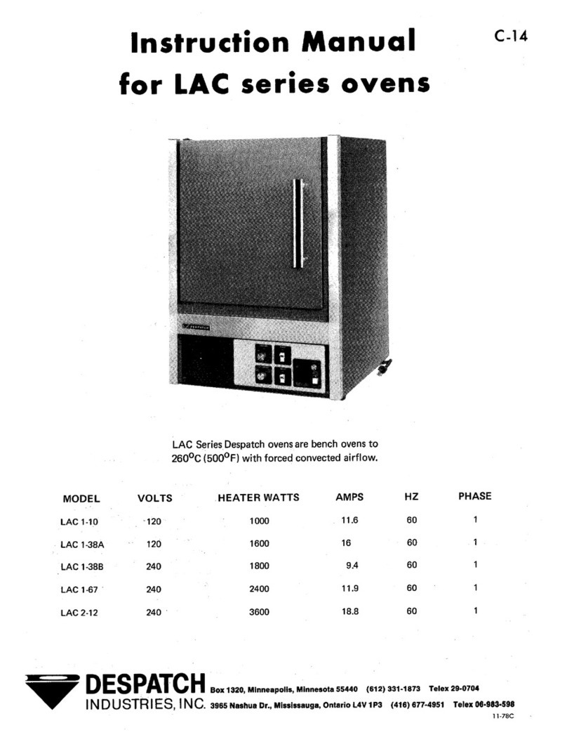
Despatch
Despatch LAC 1-10 User manual
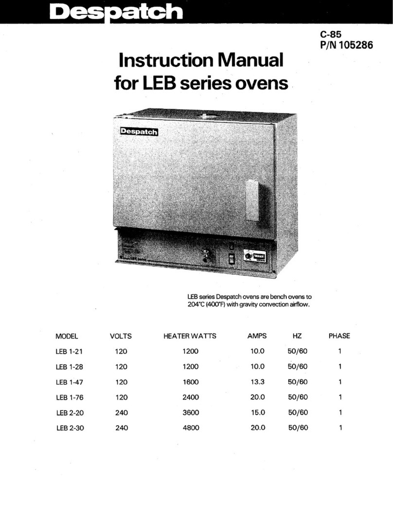
Despatch
Despatch LEB 1-21 User manual

Despatch
Despatch LBB Series User manual
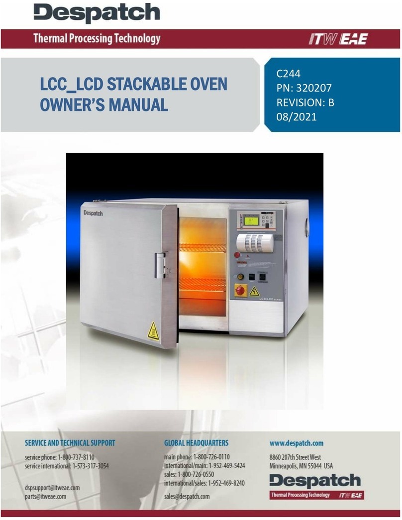
Despatch
Despatch LCC Series User manual
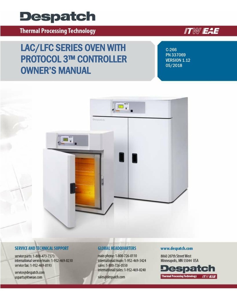
Despatch
Despatch LAC Series User manual

Despatch
Despatch LFD series User manual
Despatch
Despatch LDB 1-17AD User manual
Despatch
Despatch LCC2-14 Series User manual

