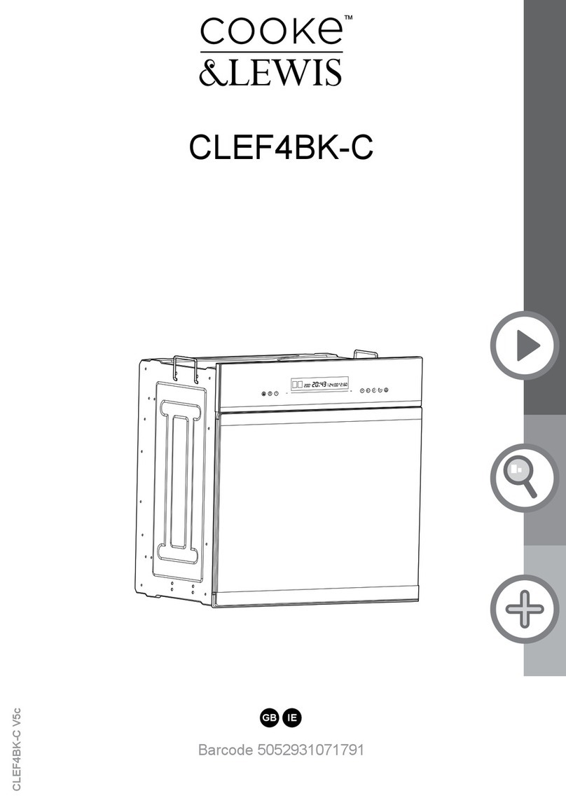
Despatch LCC2-14 Series User manual

LCC_LCD2-14 Series Oven
OWNER’S MANUAL
C245
PN: 320208
REVISION: N
03/2021

C245, 320208, REV N LCC_LCD2-14 Oven Owner’s Manual
2 of 84
©2021 ITW EAE. All rights reserved. Despatch is a registered trademark in the U.S. and other
countries. No part of the contents of this manual may be reproduced, copied or transmitted in any form
or by any means without the written permission from ITW EAE - Despatch, unless for purchaser's
personal use.
REVISION RECORD
REVISION
PREPARED BY
CHECKED BY
DATE
A
7/2002
DESCRIPTION: Initial creation.
REVISION
PREPARED BY
CHECKED BY
DATE
B
11/2002
DESCRIPTION: Drawing changes, add line connection detail.
REVISION
PREPARED BY
CHECKED BY
DATE
C
8/2003
DESCRIPTION: Update drawings.
REVISION
PREPARED BY
CHECKED BY
DATE
D
11/2003
DESCRIPTION: Updated to Protocol Plus Version 4.0.
REVISION
PREPARED BY
CHECKED BY
DATE
E
3/2004
DESCRIPTION: Update drawings, change Class A warning.
REVISION
PREPARED BY
CHECKED BY
DATE
F
6/2004
DESCRIPTION: Change water drain/outlet temp rating.
REVISION
PREPARED BY
CHECKED BY
DATE
G
8/2006
DESCRIPTION: Update to current design.
REVISION
PREPARED BY
CHECKED BY
DATE
H
5/2007
DESCRIPTION: Update drawings.

LCC_LCD2-14 Oven Owner’s Manual C245, 320208, REV N
©2021 ITW EAE. All rights reserved. Despatch is a registered trademark in the U.S. and other
countries. No part of the contents of this manual may be reproduced, copied or transmitted in any form
or by any means without the written permission from ITW EAE - Despatch, unless for purchaser's
personal use.
3 of 84
REVISION
PREPARED BY
CHECKED BY
DATE
I
7/2007
DESCRIPTION: General updates.
REVISION
PREPARED BY
CHECKED BY
DATE
J
11/2007
DESCRIPTION: Updated warranty.
REVISION
PREPARED BY
CHECKED BY
DATE
K
9/2008
DESCRIPTION: Added LL*1-* model reference.
REVISION
PREPARED BY
CHECKED BY
DATE
L
3/2009
DESCRIPTION: Updated Controller Instructions.
REVISION
PREPARED BY
CHECKED BY
DATE
M
3/2010
DESCRIPTION: Updated Declaration of Conformity.
REVISION
PREPARED BY
CHECKED BY
DATE
1
Livingston
2/2013
DESCRIPTION: Revised format and updated to Protocol 3. Version 4.
REVISION
PREPARED BY
CHECKED BY
DATE
2
Livingston
7/2013
DESCRIPTION: Minor revisions for door locks.
REVISION
PREPARED BY
CHECKED BY
DATE
3
E. Anderson
4/2016
DESCRIPTION: Revisions to -5, New drawings, formatting, etc.

C245, 320208, REV N LCC_LCD2-14 Oven Owner’s Manual
4 of 84
©2021 ITW EAE. All rights reserved. Despatch is a registered trademark in the U.S. and other
countries. No part of the contents of this manual may be reproduced, copied or transmitted in any form
or by any means without the written permission from ITW EAE - Despatch, unless for purchaser's
personal use.
REVISION
PREPARED BY
CHECKED BY
DATE
4
RDK
12/2018
DESCRIPTION: Miscellaneous updates, Class A safety notes.
REVISION
PREPARED BY
CHECKED BY
DATE
N
A. Mengesha
03/2021
DESCRIPTION: Major reformatting and content revision on all sections.

LCC_LCD2-14 Oven Owner’s Manual C245, 320208, REV N
©2021 ITW EAE. All rights reserved. Despatch is a registered trademark in the U.S. and other
countries. No part of the contents of this manual may be reproduced, copied or transmitted in any form
or by any means without the written permission from ITW EAE - Despatch, unless for purchaser's
personal use.
5 of 84
TABLE OF CONTENTS
REVISION RECORD..................................................................................2
TABLE OF CONTENTS .............................................................................5
LIST OF FIGURES.....................................................................................8
LIST OF TABLES.......................................................................................8
1. ABOUT THIS MANUAL........................................................................11
1.1. Important User Information .................................................................................... 11
1.2. Manufacturer & Service........................................................................................... 12
1.3. Organization of this Manual .................................................................................... 12
1.4. Conventions............................................................................................................ 13
2. SPECIFICATIONS................................................................................14
2.1. Model Characteristics.............................................................................................. 14
2.2. Dimensions ............................................................................................................. 14
2.3. Capacities................................................................................................................ 15
2.4. Power ..................................................................................................................... 15
2.5. Temperature........................................................................................................... 17
2.6. Capability................................................................................................................ 19
2.6.1. LCC/LCD2-14 Series .............................................................................................................................19
2.6.2. LCC/LCD2-14 Class A Ovens.................................................................................................................19
3. SAFETY ...............................................................................................20
3.1. General Safety Information ..................................................................................... 20
3.2. Lockout................................................................................................................... 20
3.2.1. Lockout Requirements ........................................................................................................................20
3.2.2. Lockout Procedure ..............................................................................................................................20
3.3. Door and Panel ....................................................................................................... 21
3.4. Maintenance........................................................................................................... 21
3.5. Electrical Power ...................................................................................................... 22
3.6. Fire ......................................................................................................................... 22
3.7. Equipment Lockout Requirements........................................................................... 23
4. THEORY OF OPERATION...................................................................24
4.1. The LCC/LCD2-14 Series Oven.................................................................................. 24
4.2. LCC/LCD2-14 Oven Operation Details....................................................................... 25
4.3. LCC/LCD2-14 Class A Oven Operation Details........................................................... 26
4.4. Standard Control System: The Protocol 3TM ............................................................. 27
4.5. HEPA Filters............................................................................................................. 28
4.5.1. Definitions of Terms ............................................................................................................................28
4.5.2. Filter Packaging, Shipping and Handling..............................................................................................29
4.5.3. HEPA Filter: Magnehelic Pressure Gauge............................................................................................30
4.5.4. Filter High Limit Controller ..................................................................................................................30
4.6. Optional Beacon Light ............................................................................................. 31
4.7. Optional High Limit Alarm with Alarm Silence.......................................................... 32

C245, 320208, REV N LCC_LCD2-14 Oven Owner’s Manual
6 of 84
©2021 ITW EAE. All rights reserved. Despatch is a registered trademark in the U.S. and other
countries. No part of the contents of this manual may be reproduced, copied or transmitted in any form
or by any means without the written permission from ITW EAE - Despatch, unless for purchaser's
personal use.
5. ASSEMBLY & SETUP .........................................................................33
5.1. Unpacking, Inspection and Reporting Damages........................................................ 33
5.1.1. Unpacking and Inspection ...................................................................................................................33
5.1.2. Reporting Damage & Missing Parts.....................................................................................................34
5.2. Setup the Oven ....................................................................................................... 34
5.2.1. Select Oven Location ...........................................................................................................................34
5.2.2. Oven Placement Requirements...........................................................................................................35
5.2.3. Oven Utility Connections.....................................................................................................................36
5.2.3.1. Nitrogen with Water-Cooled Models........................................................................................37
5.2.3.2. Air Atmosphere with Optional Water-Cooling Model...............................................................38
5.2.4. Exhaust Connections ...........................................................................................................................40
5.2.5. Wiring & Power Connections ..............................................................................................................41
5.3. HEPA Filter Handling, Installation and Burn-off........................................................ 44
5.3.1. HEPA Filter Handling and Inspection...................................................................................................45
5.3.2. HEPA Filter Installation........................................................................................................................46
5.3.3. HEPA Filter Burn-Off............................................................................................................................49
5.3.3.1. HEPA Filter Burn-Off Process.....................................................................................................49
5.3.3.2. Location of HEPA Filter Burn-Off Process..................................................................................49
5.3.3.3. Recommended HEPA Filter Burn-Off Process ...........................................................................49
6. OPERATION ........................................................................................52
6.1. General................................................................................................................... 52
6.2. Load Oven............................................................................................................... 53
6.3. Pre-Startup Checklist............................................................................................... 54
6.4. Operating Procedure............................................................................................... 55
6.4.1. HEPA Filter Burn-off and Validation Testing........................................................................................55
6.4.1.1. D.O.P. Testing............................................................................................................................55
6.4.1.2. Class 100 Testing .......................................................................................................................55
6.4.1.3. Validation Testing......................................................................................................................56
6.4.1.4. HEPA Filter Burn-off Process .....................................................................................................56
6.4.2. Start the LCC/LCD2-14 Oven ...............................................................................................................56
6.4.3. LCC/LCD2-14A Class A Oven Operation...............................................................................................58
6.4.4. Sequence of Operation for LCC/LCD2-14 Ovens Equipped with Optional Beacon Light.....................58
6.4.5. Sequence of Operation for Ovens Equipped for LCC/LCD2-14 Inert Atmosphere Oven.....................59
6.4.6. Optional High Limit Alarm with Alarm Silence ....................................................................................62
6.5. Working with Controls and Instruments .................................................................. 63
6.5.1. Protocol 3 Operating Modes ...............................................................................................................63
6.5.2. MRC5000 Setup (Optional)..................................................................................................................64
7. MAINTENANCE ...................................................................................65
7.1. Checklist ................................................................................................................. 66
7.2. Maintenance Schedule ............................................................................................ 67
7.3. HEPA Filter Pressure Reading Worksheet................................................................. 69
7.4. Door Seal ................................................................................................................ 69
7.5. Door Hinges and Latches ......................................................................................... 70
7.6. Oven Screws, Bolts and Fasteners............................................................................ 70
7.7. Check Fans .............................................................................................................. 70
7.8. Check Heater Performance...................................................................................... 70
7.9. Test Purge Timer (Class A Oven only)....................................................................... 71

LCC_LCD2-14 Oven Owner’s Manual C245, 320208, REV N
©2021 ITW EAE. All rights reserved. Despatch is a registered trademark in the U.S. and other
countries. No part of the contents of this manual may be reproduced, copied or transmitted in any form
or by any means without the written permission from ITW EAE - Despatch, unless for purchaser's
personal use.
7 of 84
7.9.1. Verify Purge Timer Setting ..................................................................................................................71
7.9.2. Verifying Operation of Purge Timer ....................................................................................................71
7.10. Test Airflow Switch (Class A Oven only) ................................................................. 71
7.10.1. Setting or Adjusting Pressure Switch.................................................................................................71
7.10.2. Verify Exhaust Fan Pressure Switch Setpoint ....................................................................................72
7.11. Lubrication............................................................................................................ 73
7.12. Process Controls and Indicators ............................................................................. 73
7.13. Check Safety Controls............................................................................................ 74
7.14. Recalibrating Controllers ....................................................................................... 74
7.15. Testing High-Limit Controller ................................................................................. 74
7.16. Routine HEPA Filter Inspection .............................................................................. 74
7.17. Inspecting & Cleaning............................................................................................ 75
7.17.1. Oven Chamber Interior......................................................................................................................75
7.17.2. Oven Exterior.....................................................................................................................................75
7.17.3. Vents..................................................................................................................................................75
7.17.4. Cleaning the LCC2-14 Series Oven.....................................................................................................75
7.17.5. Decontaminating the LCC2-14 Series Oven.......................................................................................76
7.17.6. Control Cabinet Components and Cooling Fan .................................................................................77
7.17.7. Clean-Up After Servicing ...................................................................................................................77
7.18. Replacement Parts ................................................................................................ 77
7.18.1. Replacing Protocol 3 Controller.........................................................................................................78
7.18.2. Replacing Heater Unit .......................................................................................................................78
7.18.3. Replacing HEPA Filter ........................................................................................................................79
8. TROUBLESHOOTING .........................................................................80
8.1. Possible Problems and Suggested Solutions............................................................. 80
8.2. Heater Circuit Troubleshooting................................................................................ 82
9. APPENDICES ......................................................................................84
9.1. Standard Products Warranty ................................................................................... 84
9.2. Part Lists ................................................................................................................. 84
9.3. Mechanical Drawings .............................................................................................. 84
9.4. Electrical Schematics ............................................................................................... 84

C245, 320208, REV N LCC_LCD2-14 Oven Owner’s Manual
8 of 84
©2021 ITW EAE. All rights reserved. Despatch is a registered trademark in the U.S. and other
countries. No part of the contents of this manual may be reproduced, copied or transmitted in any form
or by any means without the written permission from ITW EAE - Despatch, unless for purchaser's
personal use.
List of Figures
FIGURE 1. ELECTRICAL SPECIFICATION LABEL..............................................................................................................16
FIGURE 2. DESIGN INFORMATION AND SPECIFICATION LABEL. ..................................................................................18
FIGURE 3. DISCONNECT SWITCH. ................................................................................................................................23
FIGURE 4. LCC/LCD2-14 SERIES OVEN. ........................................................................................................................24
FIGURE 5. PROTOCOL 3 OPERATOR INTERFACE. .........................................................................................................28
FIGURE 6. THIS SIDE UP GRAPHIC................................................................................................................................29
FIGURE 7. MAGNEHELIC PRESSURE GAUGE MEASURES PRESSURE IN FRONT OF THE HEPA FILTER. .........................30
FIGURE 8. TYPICAL HIGH LIMIT CONTROLLER. NOTE RESET BUTTON ON RIGHT. .......................................................31
FIGURE 9. LCC/LCD2-14 SERIES OPTIONAL BEACON LIGHT.........................................................................................31
FIGURE 10. LCC/LCD2-14 UTILITY CONNECTIONS........................................................................................................37
FIGURE 11. EXHAUST CONNECTIONS. .........................................................................................................................40
FIGURE 12. LINE CONNECTION. ...................................................................................................................................42
FIGURE 13. CONDUIT AND DISCONNECT SWITCH/LINE CONNECTIONS. ....................................................................43
FIGURE 14. EXAMPLE HEPA FILTER (SILICONE-FREE)...................................................................................................46
FIGURE 15. LCC/LCD2-14 SIDE PANEL..........................................................................................................................47
FIGURE 16. INSTALL HEPA HIGH-TEMPERATURE FILTER (TOP SECTIONAL VIEW). ......................................................48
FIGURE 17. INSTALL HEPA STANDARD FILTER. (TOP SECTIONAL VIEW.).....................................................................48
FIGURE 18. POWER THE LCC/LCD2-14 OVEN...............................................................................................................57
FIGURE 19. CLASS A NAMEPLATE EXAMPLE. ...............................................................................................................58
FIGURE 20. NITROGEN FLOWMETER...........................................................................................................................61
FIGURE 21. ADJUST NITROGEN NEEDLE VALVE (IN COMPARTMENT BENEATH OVEN). .............................................61
FIGURE 22. ALARM SILENCE SWITCH...........................................................................................................................62
FIGURE 23. PRESSURE SWITCH MODEL-SML...............................................................................................................72
FIGURE 24. ADJUSTING THE PRESSURE SWITCH. ........................................................................................................73
FIGURE 25. PROTOCOL 3 HEATER ON INDICATOR LIGHT. ...........................................................................................83
List of Tables
TABLE 1. LCC/LCD2-14 SERIES OVEN MODEL CHARACTERISTICS. ...............................................................................14
TABLE 2. LCC/LCD2-14 SERIES OVEN DIMENSIONS. ....................................................................................................14
TABLE 3. LCC/LCD2-14 SERIES OVEN CAPACITIES........................................................................................................15
TABLE 4. ELECTRICAL SPECIFICATIONS. .......................................................................................................................16
TABLE 5. LCC/LCD2-14 SERIES OVEN TEMPERATURE RANGES ....................................................................................17
TABLE 6. UTILITY CONNECTIONS (REFER TO FIGURE 10).............................................................................................36
TABLE 7. EXHAUST CONNECTION REQUIREMENTS. ....................................................................................................41
TABLE 8. MRC 5000 SETTINGS. ....................................................................................................................................64
TABLE 9. PREVENTIVE MAINTENANCE SCHEDULE.......................................................................................................67
TABLE 10. HEPA FILTER PRESSURE READING WORKSHEET. ........................................................................................69
TABLE 11. POSSIBLE PROBLEMS AND SUGGESTED SOLUTIONS. .................................................................................80
TABLE 12. ERROR MESSAGES, POSSIBLE CAUSES, AND REMEDIAL STEPS...................................................................83

LCC_LCD2-14 Oven Owner’s Manual C245, 320208, REV N
©2021 ITW EAE. All rights reserved. Despatch is a registered trademark in the U.S. and other
countries. No part of the contents of this manual may be reproduced, copied or transmitted in any form
or by any means without the written permission from ITW EAE - Despatch, unless for purchaser's
personal use.
9 of 84
Danger!
Failure to heed warnings in this instruction manual and on the
oven could result in personal injury, property damage or death.
1. BEFORE OPERATING THIS EQUIPMENT, CAREFULLY READ THIS INSTRUCTION
MANUAL.
2. THE USER(S) OF THIS EQUIPMENT MUST COMPLY WITH OPERATING
PROCEDURES AND TRAINING OF OPERATING PERSONNEL AS STATED IN THE
MOST RECENT OCCUPATIONAL SAFETY AND HEALTH ACT (OSHA), SECTION 5
AND THE MOST RECENT NATIONAL FIRE PROTECTION ASSOCIATION (NFPA)
SECTION 86.
3. THIS EQUIPMENT IS DESIGNED FOR A SPECIFIED AMOUNT OF VOLATILE.
EXCEEDING THIS AMOUNT COULD RESULT IN AN EXPLOSION. REFER TO
DESIGN SPECIFICATION DECAL LOCATED ON THE OVEN FOR THE EXACT
AMOUNT OF VOLATILE, EXHAUST AND FRESH AIR REQUIRED.
4. HIGH VOLTAGE IS PRESENT ON THIS EQUIPMENT. SERVICE SHOULD BE
PERFORMED BY AUTHORIZED PERSONNEL ONLY.
5. DO NOT ATTEMPT ANY SERVICE ON THIS EQUIPMENT WITHOUT PERFORMING
PROPER LOCK-OUT PROCEDURE.
6. IN CASE OF FIRE:
a. LEAVE DOOR(S) AS THEY ARE.
b. SHUT OFF ELECTRICITY.
c. SHUT OFF FUEL.
d. CALL THE FIRE DEPARTMENT
e. STAY AWAY.

C245, 320208, REV N LCC_LCD2-14 Oven Owner’s Manual
10 of 84
©2021 ITW EAE. All rights reserved. Despatch is a registered trademark in the U.S. and other
countries. No part of the contents of this manual may be reproduced, copied or transmitted in any form
or by any means without the written permission from ITW EAE - Despatch, unless for purchaser's
personal use.
Danger!
Failure to heed warnings in this instruction manual and on the
oven could result in personal injury, property damage or death.
Hi Limit Controls
ITW EAE –Despatch Recommends
A Hi-Limit control for ALL Ovens and Furnaces
A HI-LIMIT CONTROL IS INCLUDED ON THIS EQUIPMENT.
IT IS INSTALLED TO PROTECT THE EQUIPMENT.
The location of the Hi-Limit Sensor is at the supply duct louver and has been
chosen to supervise that temperature. The Hi-Limit controller should be set to
approximately 5⁰C to 10⁰C (9⁰F to 18⁰F) higher than the maximum operating
temperature. This setting will eliminate nuisance shutdowns when operating at
the maximum temperature of the equipment and still give maximum protection
to the equipment.
ITW EAE CANNOT BE RESPONSIBLE FOR EITHER THE PROCESS
OR QUALITY OF THE PRODUCT BEING PROCESSED.
If the product on which the equipment is being used is critical of over
temperature, the Hi-Limit may be used as a “Process Hi-Limit”. The sensor
element is located on the supply duct where the hot air enters the work chamber.
The temperature setting on the “Process Hi-Limit” should be set somewhat below
the temperature at which the product would be damaged. If the product has an
ignition temperature at which it would ignite, the setting should be well below
this temperature. It is recommended that a certified instrument be used to make
proper setting.
IT IS THE PURCHASER’S RESPONSIBILITY THAT THE “EQUIPMENT” HI-
LIMIT AND/OR THE “PROCESS” HI-LIMIT BE SET PER THE
INSTRUCTIONS ON THIS SHEET AND ALSO THE INSTRUCTION SHEET
FOR THE PARTICULAR HI-LIMIT INSTRUMENT FURNISHED WITH THIS
EQUIPMENT.

LCC_LCD2-14 Oven Owner’s Manual C245, 320208, REV N
©2021 ITW EAE. All rights reserved. Despatch is a registered trademark in the U.S. and other
countries. No part of the contents of this manual may be reproduced, copied or transmitted in any form
or by any means without the written permission from ITW EAE - Despatch, unless for purchaser's
personal use.
11 of 84
1. ABOUT THIS MANUAL
1.1. Important User Information
All rights reserved. No part of the contents of this manual may be reproduced,
copied, or transmitted in any form or by any means including graphic, electronic,
or mechanical methods or photocopying, recording, or information storage and
retrieval systems without the written permission of the publisher, unless it is for
the purchaser's personal use.
The information in this manual is subject to change without notice and does not
represent a commitment on the part of ITW EAE - Despatch. ITW EAE –Despatch
does not assume any responsibility for any errors that may appear in this manual.
In no event will ITW EAE –Despatch be liable for technical or editorial omissions
made herein, nor for direct, indirect, special, incidental, or consequential
damages resulting from the use or defect of this manual.
Values displayed on screens are examples only. Though those
values may be typical, contact ITW EAE - Despatch for the final
value.
Users of this equipment must comply with operating procedures
and training of operation personnel as required by the most
recent Occupational Safety and Health Act (OSHA), Section 5 and
relevant safety standards, as well as other safety rules and
regulations of state and local governments. Refer to the relevant
safety standards in OSHA and the most recent National Fire
Protection Association (NFPA), section 86.
Danger!
Only fully trained and qualified personnel should setup and
maintain this equipment. Improper setup and operation of this
equipment could cause an explosion that may result in
equipment damage, personal injury or possible death!

C245, 320208, REV N LCC_LCD2-14 Oven Owner’s Manual
12 of 84
©2021 ITW EAE. All rights reserved. Despatch is a registered trademark in the U.S. and other
countries. No part of the contents of this manual may be reproduced, copied or transmitted in any form
or by any means without the written permission from ITW EAE - Despatch, unless for purchaser's
personal use.
The information in this document is not intended to cover all possible conditions
and situations that might occur. The end user must exercise caution and common
sense when installing or maintaining ITW EAE - Despatch products. If any
questions or problems arise, call ITW EAE - Despatch at 1-800-726-0110 or 1-952-
469-5424.
1.2. Manufacturer & Service
The LCC/LCD2-14 Series oven is manufactured by ITW EAE - Despatch.
ITW EAE - Despatch has specialized in thermal processing for over 100 years.
Technical expertise gained over those years helps provide innovative solutions to
critical applications in vertical markets and cutting-edge technology worldwide.
ITW EAE - Despatch products are backed by a drive for long-term customer
satisfaction and a strong sense of responsibility. The worldwide network of
factory-trained Service Professionals is available to support your ITW EAE -
Despatch equipment. From full service preventive maintenance to routine repair
and certified calibration and uniformity, the ITW EAE - Despatch service network
is positioned to respond to your business needs. Our service programs are
customized to meet your specific needs using our Advantage Service Assurance
Program (ASAP). For more information on ASAP, visit www.despatch.com.
1.3. Organization of this Manual
This owner’s manual contains the most comprehensive set of information for the
ITW EAE - Despatch LCC/LCD2-14 Series ovens, including installation instructions,
theory of operation, and operating instructions, among other things. To save time
and expense in case of trouble, it is urged that the operators search this manual
for helpful suggestions before requesting factory assistance.
Danger!
Failure to heed warnings in this instruction manual and on the
oven could result in personal injury, property damage or death

LCC_LCD2-14 Oven Owner’s Manual C245, 320208, REV N
©2021 ITW EAE. All rights reserved. Despatch is a registered trademark in the U.S. and other
countries. No part of the contents of this manual may be reproduced, copied or transmitted in any form
or by any means without the written permission from ITW EAE - Despatch, unless for purchaser's
personal use.
13 of 84
1.4. Conventions
This icon signifies information that describes an unsafe condition
that may result in death, serious injury, or damage to the
equipment.
Danger!
Danger is the signal word used to indicate a hazardous situation
that, if not avoided, will result in death or severe injury.
Warning!
Warning is the signal word used to indicate a hazardous
situation that, if not avoided, could result in death or severe
injury.
Caution!
Caution is the signal word used to indicate a hazardous situation
that, if not avoided, could result in moderate or minor injury.
Notice
Notice is the signal word used to indicate a hazardous situation
that, if not avoided, could result in property damage.
This icon signifies important supplemental information.
Bold, 10-point Sans Serif typeface indicates a specific key or
button on screen to click.

C245, 320208, REV N LCC_LCD2-14 Oven Owner’s Manual
14 of 84
©2021 ITW EAE. All rights reserved. Despatch is a registered trademark in the U.S. and other
countries. No part of the contents of this manual may be reproduced, copied or transmitted in any form
or by any means without the written permission from ITW EAE - Despatch, unless for purchaser's
personal use.
2. SPECIFICATIONS
The LCC/LCD2-14 oven is not intended to process solvents or
other volatile or flammable materials. Oven forced exhaust is
intended for cooling purposes only on standard and inert
(nitrogen) models.
Order an LCC/LCD2-14 oven with the Class A option to process
solvents or other volatile or flammable materials.
2.1. Model Characteristics
Table 1. LCC/LCD2-14 Series Oven Model Characteristics.
Model
Atmosphere
Max Temp °C
LCC2-14-5
Air
260
LCD2-14-5
Air
350
LCC2-14N-5
Inert
260
LCD2-14N-5
Inert
350
LCC2-14A-5
Class A
260
LCD2-14A-5
Class A
350
2.2. Dimensions
Table 2. LCC/LCD2-14 Series Oven Dimensions.
Models
Chamber Size
inches (cm)
Capacity
ft3(liters)
Overall Size
inches (cm)
Maximum
number
of Shelves
W1
D
H
W
D
H
LCC/LCD2-14
25.5
(64)
26
(66)
37
(94)
14
(396)
47.5
(121)
41.5
(105)
71
(180)
11
NOTE –refer to assembly drawing for exact dimensions
1
Clear opening width is reduced by 1.5 inches (3.8cm) due to ¾ inch (1.9cm) shelf supports on each side.

LCC_LCD2-14 Oven Owner’s Manual C245, 320208, REV N
©2021 ITW EAE. All rights reserved. Despatch is a registered trademark in the U.S. and other
countries. No part of the contents of this manual may be reproduced, copied or transmitted in any form
or by any means without the written permission from ITW EAE - Despatch, unless for purchaser's
personal use.
15 of 84
2.3. Capacities
Table 3. LCC/LCD2-14 Series Oven Capacities
Models
LCC/LCD2-14
Maximum Load:
Lbs
(KG)
400
(181)
Maximum Shelf Capacity:
Lbs
(KG)
50
(23)
Recirculating fan:
CFM/LPS
(HP)
950/448
1.5
Net weight (Approximate):
Lbs
(KG)
955
(434)
Shipping weight (Approximate):
Lbs
(KG)
1050
(477)
Exhaust fan:
CFM/LPS
(HP)
85/40
0.03
Exhaust Opening Diameter:
Inch
(mm)
4
102
2.4. Power
If the line voltage for your LCC/LCD2-14 Series oven varies more than 10% from
the oven voltage rating, electrical components such as relays and temperature
controls may operate erratically. Power connection is performed by the user.
•If the line voltage is lower than the oven voltage rating, heat-up time may be
significantly longer, and motors may overload or run hot
•If the line voltage is higher than the nameplate rating, motors may run hot and
draw excessive amperage

C245, 320208, REV N LCC_LCD2-14 Oven Owner’s Manual
16 of 84
©2021 ITW EAE. All rights reserved. Despatch is a registered trademark in the U.S. and other
countries. No part of the contents of this manual may be reproduced, copied or transmitted in any form
or by any means without the written permission from ITW EAE - Despatch, unless for purchaser's
personal use.
Table 4. Electrical Specifications.
Models
Volts
Amps
Phase
Hertz
Heater
(kW)
LCC/LCD2-14
208
51.6
3
50/60
16
240
46.5
3
50/60
16
380
29.4
3
50
15.1
415
28.6
3
50
16
480
25.2
3
60
16
Refer to the Electrical Specifications on your oven for specifics pertaining to your
oven (Figure 1).
Figure 1. Electrical Specification Label.

LCC_LCD2-14 Oven Owner’s Manual C245, 320208, REV N
©2021 ITW EAE. All rights reserved. Despatch is a registered trademark in the U.S. and other
countries. No part of the contents of this manual may be reproduced, copied or transmitted in any form
or by any means without the written permission from ITW EAE - Despatch, unless for purchaser's
personal use.
17 of 84
2.5. Temperature
Table 5. LCC/LCD2-14 Series Oven Temperature Ranges
Model
Initial –Final Temperature
LCC/LCD2-14
Time to Temperature
(approximate
minutes)
(no load)
50°C –100°C
3 min.
50°C –200°C
9 min.
50°C –260°C
15 min.
50°C –350°C2
35 min.
Cooling Time to Temp
Minutes
(No Load)3,4
100°C –65°C
41 min. (air atmos.)
15 min. (nitrogen atmos.)4
175°C –65°C
82 min. (air atmos.)
20 min. (nitrogen atmos.)4
260°C –65°C
95 min. (air atmos.)
25 min. (nitrogen atmos.)4
350°C –65°C2
116 min. (air atmos.)
30 min. (nitrogen atmos.)4
Temperature
Uniformity at5
100°C
±1°C
175°C
±2°C
260°C
±3°C
350°C2
±3.5°C
Maximum Operating
Temperature
LCC
260°C
LCD
350°C
Operating Range
w/20°C Ambient
LCC
50°C-260°C (air atmos.)
30°C-260°C (nitrogen atmos.)
LCD
50°C-350°C (air atmos.)
30°C-350°C (nitrogen atmos.)
Control Stability
±0.5°C
2
For LCD only, LCC maximum temperature: 260°C.
3
Minimum operating temperatures and cooling times are based on a 20°C ambient temperature measured at the
fresh air inlet.
4
Based on cooling water supplied at 3 GPM (11 lpm), 13°C (55°F).
5
Uniformity figures are based on a nine-point test conducted in an empty oven after stabilization period.
Uniformity can vary slightly depending on unit and operating conditions. Class 100 HEPA filtration will limit ramp
rates. Specifications are subject to change without notice.

C245, 320208, REV N LCC_LCD2-14 Oven Owner’s Manual
18 of 84
©2021 ITW EAE. All rights reserved. Despatch is a registered trademark in the U.S. and other
countries. No part of the contents of this manual may be reproduced, copied or transmitted in any form
or by any means without the written permission from ITW EAE - Despatch, unless for purchaser's
personal use.
Refer to the Design Information and Specification label on your oven for
temperature specifics pertaining to your oven (Figure 2).
Figure 2. Design Information and Specification
Label.

LCC_LCD2-14 Oven Owner’s Manual C245, 320208, REV N
©2021 ITW EAE. All rights reserved. Despatch is a registered trademark in the U.S. and other
countries. No part of the contents of this manual may be reproduced, copied or transmitted in any form
or by any means without the written permission from ITW EAE - Despatch, unless for purchaser's
personal use.
19 of 84
2.6. Capability
2.6.1. LCC/LCD2-14 Series
The LCC/LCD2-14 Series ovens are not designed to handle any amount of solvents
or other flammable materials.
2.6.2. LCC/LCD2-14 Class A Ovens
LCC/LCD2-14 Class A ovens are specifically designed for NFPA 86 Class A
requirements in which flammable solvents are present. They include a pressure
relief panel, purge timer and exhaust fan. Please note the solvent handling
capabilities and do not exceed those capabilities.
The ovens have an explosion relief panel and purge interlock devices:
•If the LEL (Lower Explosive Limit) is exceeded and an explosive mixture is
ignited in the oven, the explosion relief will rupture, preventing any more
physical damage to the oven.
•An airflow switch on the exhaust to verify exhaust fan is operating.
•A purge timer preset to keep heater off until the purge period is complete.
The preset purge period guarantees four complete air exchanges to remove
volatiles in the chamber before the heater can be turned on.
•Any failure of these devices will shut down the heater, preventing further
processing until the condition is remedied.
The LCC/LCD2-14 Class A option requires the exhaust fan be
wired ON at all times.
Danger!
LFC/LFD2-14A Class A ovens are designed for a specific amount
of solvent. Exceeding this amount could result in an explosion.
Do not process closed containers of any substance or liquid in
this oven because they may explode under heat. In case of fire,
leave door(s) as they are. Shut off electricity. Shut off fuel. Call
the fire department. Stay away.

C245, 320208, REV N LCC_LCD2-14 Oven Owner’s Manual
20 of 84
©2021 ITW EAE. All rights reserved. Despatch is a registered trademark in the U.S. and other
countries. No part of the contents of this manual may be reproduced, copied or transmitted in any form
or by any means without the written permission from ITW EAE - Despatch, unless for purchaser's
personal use.
3. SAFETY
3.1. General Safety Information
Do not work on the LCC/LCD2-14 Series oven without reading and understanding
this section which contains important information and warnings. Ignoring these
warnings can result in death, serious injury or damage to the machine and
product.
3.2. Lockout
Machine lockout places the LCC/LCD2-14 Series oven into a zero-energy state and
prevents accidental machine start up. Always follow the Lockout Procedure
described in this Section before cleaning, maintaining, or repairing the LCC/LCD2-
14 Series oven. An accidental start-up, while working on the LCC/LCD2-14 Series
oven, can result in serious injury or death.
3.2.1. Lockout Requirements
1. Every power source that can energize any element of the LCC/LCD2-14
Series oven must be shut off at the closest possible power source. This
includes air, water, and electricity, including the Disconnect Switch.
2. After energy sources are locked out, test to ensure circuits are de-energized.
3.2.2. Lockout Procedure
Personnel authorized to lockout equipment must have the necessary locks to
perform the lockout.
1. Physically disconnect all electrical power to the machine or lockout the
appropriate breaker or disconnects.
2. Close all valves and bleed off any pressure.
3. Test for power by attempting a start with the machine controls.
4. Identify the Lockout Condition with a tag on the electrical disconnect and
pneumatic shut off valve.
5. When work is complete, remove all tags and restore the machine to its
working state.
This manual suits for next models
1
Table of contents
Other Despatch Oven manuals
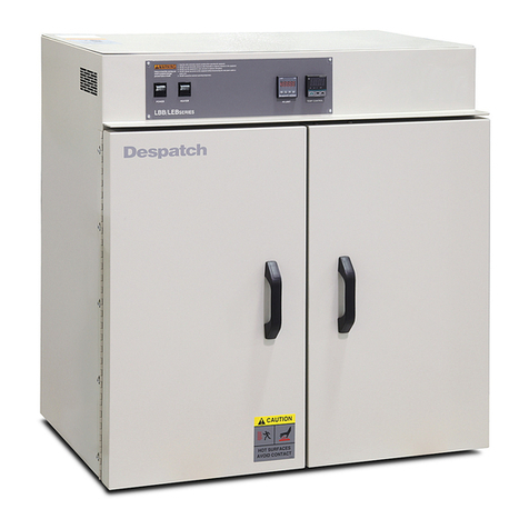
Despatch
Despatch LBB 1-23 User manual
Despatch
Despatch LCC Series User manual

Despatch
Despatch LFD series User manual
Despatch
Despatch LBB Series User manual
Despatch
Despatch LAC-6 Series User manual
Despatch
Despatch LDB 1-17AD User manual

Despatch
Despatch LCC Series User manual
Despatch
Despatch LAC Series User manual
Despatch
Despatch LAC 1-10 User manual
Despatch
Despatch LEB 1-21 User manual


