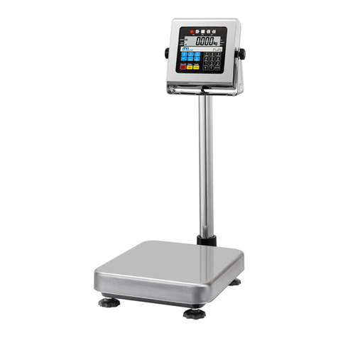
Detecto icon User manual

3300-0192-0M Rev D 01/17 1
icon
Digital Clinical Scale
Owner’s Manual

3300-0192-0M Rev D 01/172

3300-0192-0M Rev D 01/17 3
PRECAUTIONS
Before using this scale, read this manual
and pay special attention to all
"NOTIFICATION" symbols:
IMPORTANT ELECTRICAL
WARNING
INTRODUCTION
Thank you for purchasing our Detecto icon®Digital Clinical Scale. It has been manufactured
with quality and reliability at our factory in Webb City, MO USA. Your scale has been tested
before leaving our factory to insure accuracy and dependability for years to come.
This manual is provided to guide you through installation and operation of your scale. Please
read it thoroughly before attempting to install or operate your scale and keep it handy for future
reference.
COPYRIGHT
All rights reserved. Reproduction or use, without expressed written permission, of editorial or
pictorial content, in any manner, is prohibited. No patent liability is assumed with respect to
the use of the information contained herein.
DISCLAIMER
While every precaution has been taken in the preparation of this manual, the Seller assumes
no responsibility for errors or omissions. Neither is any liability assumed for damages resulting
from use of the information contained herein. All instructions and diagrams have been
checked for accuracy and ease of application; however, success and safety in working with
tools depend to a great extent upon the individual accuracy, skill and caution. For this reason
the Seller is not able to guarantee the result of any procedure contained herein. Nor can they
assume responsibility for any damage to property or injury to persons occasioned from the
procedures. Persons engaging the procedures do so entirely at their own risk.
FCC COMPLIANCE STATEMENT
This equipment generates, uses and can radiate radio frequency and if not installed and used
in accordance with the instruction manual, may cause interference to radio communications. It
has been designed within the limits for a Class A computing device pursuant to Subpart J of
Part 15 of FCC rules to provide reasonable protection against such interference when
operated in a commercial environment. Operation of this equipment in a residential area may
cause interference in which case the user will be responsible to take whatever measures
necessary to correct the interference.
You may find the booklet “How to Identify and Resolve Radio TV Interference Problems”
prepared by the Federal Communications Commission helpful. It is available from the U.S.
Government Printing Office, Washington, D.C. 20402. Request stock No. 001-000-00315-4.
I
Serial Number _____________________
Date of Purchase __________________
Purchased From ___________________
__________________________________
__________________________________
__________________________________
RETAIN THIS INFORMATION FOR FUTURE USE

3300-0192-0M Rev D 01/174
PROPER DISPOSAL
When this device reaches the end of its useful life, it must be properly disposed of. It must not
be disposed of as unsorted municipal waste. Within the European Union, this device should
be returned to the distributor from where it was purchased for proper disposal. This is in
accordance with EU Directive 2002/96/EC. Within North America, the device should be
disposed of in accordance with the local laws regarding the disposal of waste electrical and
electronic equipment.
It is everyone’s responsibility to help maintain the environment and to reduce
the effects of hazardous substances contained in electrical and electronic
equipment on human health. Please do your part by making certain that this
device is properly disposed of. The symbol shown to the right indicates that
this device must not be disposed of in unsorted municipal waste programs.
CAUTION
CAUTION: RISK OF EXPLOSION IF BATTERY IS REPLACED BY AN
INCORRECT TYPE. DISPOSE OF USED BATTERIES ACCORDING TO THE
INSTRUCTIONS.
ATTENTION: RISQUE D'EXPLOSION SI LA BATTERIES EST REMPLACE'E PAR
UN TYPE INCORRECT. REJETEZ LES BATTERIES UTILISE'ES SELON LES
INSTRUCTIONS.
II

3300-0192-0M Rev D 01/17 5
TABLE OF CONTENTS
SPECIFICATIONS . . . . . . . . . . . . . . . . . . . . . . . . . . . . . . . . . . . . . . . . . . . . . . . . . . . Page 1
Standard Features . . . . . . . . . . . . . . . . . . . . . . . . . . . . . . . . . . . . . . . . . . . . . . . . . Page 1
Optional Features . . . . . . . . . . . . . . . . . . . . . . . . . . . . . . . . . . . . . . . . . . . . . . . . . Page 1
SITE PREPARATION REQUIREMENTS. . . . . . . . . . . . . . . . . . . . . . . . . . . . . . . . . . Page 3
UNPACKING . . . . . . . . . . . . . . . . . . . . . . . . . . . . . . . . . . . . . . . . . . . . . . . . . . . . . . . Page 4
ASSEMBLY . . . . . . . . . . . . . . . . . . . . . . . . . . . . . . . . . . . . . . . . . . . . . . . . . . . . . . . . Page 4
PLACING THE SCALE . . . . . . . . . . . . . . . . . . . . . . . . . . . . . . . . . . . . . . . . . . . . . . . Page 6
INTERCONNECTIONS . . . . . . . . . . . . . . . . . . . . . . . . . . . . . . . . . . . . . . . . . . . . . . . Page 6
AC Power Adapter . . . . . . . . . . . . . . . . . . . . . . . . . . . . . . . . . . . . . . . . . . . . . . . . . Page 6
USB . . . . . . . . . . . . . . . . . . . . . . . . . . . . . . . . . . . . . . . . . . . . . . . . . . . . . . . . . . . . Page 6
Height Rod – Detecto Sonar Height Rod . . . . . . . . . . . . . . . . . . . . . . . . . . . . . . . . Page 6
Batteries . . . . . . . . . . . . . . . . . . . . . . . . . . . . . . . . . . . . . . . . . . . . . . . . . . . . . . . . . Page 6
Battery Status . . . . . . . . . . . . . . . . . . . . . . . . . . . . . . . . . . . . . . . . . . . . . . . . . . . . Page 7
Battery Installation/Replacement . . . . . . . . . . . . . . . . . . . . . . . . . . . . . . . . . . . . . . Page 7
UNITS SELECTION . . . . . . . . . . . . . . . . . . . . . . . . . . . . . . . . . . . . . . . . . . . . . . . . . . Page 8
KEYPAD FUNCTIONS . . . . . . . . . . . . . . . . . . . . . . . . . . . . . . . . . . . . . . . . . . . . . . . Page 9
ANNUNCIATORS . . . . . . . . . . . . . . . . . . . . . . . . . . . . . . . . . . . . . . . . . . . . . . . . . . . Page 11
OPERATION . . . . . . . . . . . . . . . . . . . . . . . . . . . . . . . . . . . . . . . . . . . . . . . . . . . . . . . Page 12
Zero Weight Display . . . . . . . . . . . . . . . . . . . . . . . . . . . . . . . . . . . . . . . . . . . . . . . Page 12
Basic Operation . . . . . . . . . . . . . . . . . . . . . . . . . . . . . . . . . . . . . . . . . . . . . . . . . . . Page 12
Basic Operation with ID – (No BMI) . . . . . . . . . . . . . . . . . . . . . . . . . . . . . . . . . . . . Page 12
Body Mass Index (BMI) Operation – (No ID) . . . . . . . . . . . . . . . . . . . . . . . . . . . . . Page 13
Body Mass Index (BMI) Operation with ID . . . . . . . . . . . . . . . . . . . . . . . . . . . . . . . Page 13
Body Mass Index (BMI) Operation, Manually Entering Known Height . . . . . . . . . Page 14
Body Mass Index (BMI) Operation with ID, Manually Entering Known Height . . . Page 14
SCALE SETUP . . . . . . . . . . . . . . . . . . . . . . . . . . . . . . . . . . . . . . . . . . . . . . . . . . . . . Page 15
SCALE CALIBRATION . . . . . . . . . . . . . . . . . . . . . . . . . . . . . . . . . . . . . . . . . . . . . . . Page 21
ERROR AND OPERATION MESSAGES . . . . . . . . . . . . . . . . . . . . . . . . . . . . . . . . . Page 23
BEFORE YOU CALL SERVICE . . . . . . . . . . . . . . . . . . . . . . . . . . . . . . . . . . . . . . . . Page 24
CARE AND CLEANING . . . . . . . . . . . . . . . . . . . . . . . . . . . . . . . . . . . . . . . . . . . . . . Page 25
PARTS IDENTIFICATION . . . . . . . . . . . . . . . . . . . . . . . . . . . . . . . . . . . . . . . . . . . . . Page 26
STATEMENT OF LIMITED WARRANTY . . . . . . . . . . . . . . . . . . . . . . . . . . . . . . . . . Page 32
III


3300-0192-0M Rev D 01/17 1
SPECIFICATIONS
Capacity: 600 lb x 0.2 lb / 1,000 lb x 0.5 lb
300 kg x 0.1 kg / 500 kg x 0.2 kg
Weighing/Height Units: Pounds/Inch (lb, in) or Kilograms/Centimeters (kg, cm)
Platform Size: 17 in W x 17 in D x 1.5 in H
(43 cm W x 43 cm D x 3.8 cm D)
Overall Dimensions: 17 in W x 18.5 in D x 88.5 in H
(43 cm W x 47 cm D x 224.8 cm H)
Sonar Height Rod Measures: 24” (2’) – 86” (7’2”) x 0.2 in
(60 cm – 218 cm) x 0.5 cm
Display Type: 3.2 in (diagonal) full color TFT display
320x240 resolution
Number of Characters: Weight: 5 digit, 0.8 in (20 mm) high
Height: 4 digit, 0.35 in (9 mm) high
BMI: 3 digit, 0.35 in (9 mm) high
Touch Screen: Resistive touch panel covering the display
Keys: Mechanical switch type, Power, Zero, Lock/Release, ID,
Cycle Display Mode, Menu, Print
Power Requirements: Included 100 to 240 VAC 50/60Hz 12 VDC 1A wall plug-in
UL/CSA listed AC power adapter (Cardinal part number
6800-1045) or optional 12 “AA” cell Alkaline, Ni-Cad or NiMH
batteries (not included)
Operating Environment: Operated Temperature Range: 14 to 104 ºF (-10 to +40 ºC)
Humidity: 0 to 90% non-condensing
Communication Interfaces: RS232, USB
Standard Features:
Dual Range Weight
1 RS232 Serial Port
Auto Weight Lock Feature
1 USB-B Port
StableSENSE® 1 Adjustable Filtering
Sonar Height Rod
8-Digit Numeric Patient ID
Optional Features:
Wi-Fi
WAConnect, Welch Allyn®Interface
Bluetooth
1StableSENSE® is a digital filter utilizing proprietary software algorithms to remove or greatly
reduce changes in the weight display resulting from movement on the scale platform.
StableSENSE® can be used with clinical scales to lessen the effects of the patient’s
movement or vibration on the scale. Any application affected by vibration or movement on
the scale platform can benefit using StableSENSE®.

3300-0192-0M Rev D 01/172
This page intentionally left blank.

3300-0192-0M Rev D 01/17 3
SITE PREPARATION REQUIREMENTS
The icon Digital Clinical Scale is a precision weight indicating instrument. As with any
precision instrument, it requires an acceptable environment to operate at peak performance
and reliability. This section is provided to assist you in obtaining such an environment.
Environmental
For indoor use only.
Suitable for dry environments only RH < 90% and non-condensing environments.
NEVER allow scale to get wet.
The scale meets or exceeds all certification requirements within a temperature range
of 14 to 104 °F (-10 to +40 °C).
The scale should be placed out of direct sunlight and to provide adequate air circulation,
keep the area around the scale clear.
Do not place the scale directly in front of a heating or cooling vent. Such a location will
subject it to sudden temperature changes, which may result in unstable weight readings.
Insure that the scale has good, clean AC power and is properly grounded. In areas subject
to lightning strikes, additional protection to minimize lightning damage, such as surge
suppressors, should be installed.
Electrical Power
The icon Digital Clinical Scale has been designed to operate from a 100 to 240 VAC
50/60Hz 12 VDC 1A wall plug-in UL/CSA listed AC power adapter. Note that a special
order is not required for operation at 230 VAC.
The socket-outlet supplying power to the scale should be near the scale and should be
easily accessible.
On installations requiring 230 VAC power, it is the responsibility of the customer to
have a qualified electrician install the proper power adapter plug that conforms to
national electrical codes and local codes and ordinances.
Electrical Noise Interference
To prevent electrical noise interference, make certain all air conditioning and heating
equipment, lighting or other equipment with heavily inductive loads, such as welders, motors
and solenoids are on circuits separate from the system. Many of these disturbances can
seriously affect the operation of the system. These sources of disturbances must be
identified and steps must be taken to prevent possible adverse effects on the system.
Examples of available alternatives include isolation transformers, power regulators,
uninterruptible power supplies, or simple line filters.

3300-0192-0M Rev D 01/174
UNPACKING
Carefully remove the icon Digital Clinical Scale from the shipping carton and inspect it for any
damage that may have taken place during shipment. Keep and use the original carton and
packing material for return shipment if it should become necessary. The purchaser is
responsible for filing all claims for any damages or loss incurred during transit. Remove all
plastic wrapping, foam fillers and cardboard material from scale platform, display and other
components. You should have the following components:
Column with attached Display and Sonar Bracket
Column Cover
Scale Base
Scale Base Cover
Sonar Height Rod
AC Power Adapter
ASSEMBLY
TOOLS REQUIRED:
3/16” Allen wrench
#2 Phillips Screwdriver
1. Place the scale base on a level floor.
2. Insert the column cover onto the column.
3. Position the column over the opening in the scale base and then plug the modular
connector from the column into the socket in the scale base.
4. Insert the column into the scale base.
5. Using the 3/16” Allen wrench, evenly tighten the (4) Allen head screws on the back of
the scale base to secure column to scale base.
NOTE: The nuts on the front of the column opening in the scale base may turn
as you are tightening the Allen head screws.
This is normal. DO NOT use a wrench or other tool to hold the nut to keep it
from turning!
6. Slide the column cover down onto the base. Note that you may have to pull the cover
out slightly to clear the AC power jack.
7. Remove (6) screws securing sonar bracket to column and set bracket aside.
8. Align wire connector from the end of Sonar tube with the wire connector from the back
of column and plug together.
9. Insert the connector into the hole on back of column.
10. Place the sonar tube on back of the column and hold in place.
11. Place the bracket over the sonar tube and align the holes in the bracket with the holes
in the column.
IMPORTANT! Make sure the bend of the sonar tube is against the back throat of the
column.
12. Insert the screws removed earlier and using the #2 Phillips screwdriver, tighten the
screws to secure the sonar bracket to the column.
13. Place the scale base cover on the scale base and press down on both sides of the
cover. Note that a clicking sound will occur when the cover is snapped in place.
14. Scale is now ready for operation.
NOTE: For instructions on powering the scale using the AC power adapter or for
instructions on how to install batteries, refer to the INTERCONNECTIONS
section of this manual.

3300-0192-0M Rev D 01/17 5
Step 1 Step 2 Step 3
Step 4 Step 5 Step 6
Step 7 Step 8 Step 9
Step 10 Step 11 Step 12

3300-0192-0M Rev D 01/176
PLACING THE SCALE
For indoor use only.
Place scale on a flat, level floor or low-cut carpet away from heating and cooling vents.
Make certain the AC Power Adapter cord is out of the way of normal traffic to avoid a
trip hazard.
NEVER allow scale to get wet.
Check to make certain the scale is level. The level indicator is
located at the rear of the scale. If the scale is not level (the
bubble will not be centered), position the scale as required to
center the bubble and attain a level scale.
NOTE: Any time the scale is moved or re-located, be sure to check the level
bubble to ensure the scale is level before using.
INTERCONNECTIONS
The output and power connections to the scale are made on the rear of the scale base.
AC Power Adapter
To power the scale using the 12VDC wall plug-in UL/CSA listed AC power adapter, connect
the plug from the adapter into the power jack on the back of the scale base and then plug
the power adapter into the proper electrical outlet. On models requiring 230 VAC, it is the
customer’s responsibility to obtain the correct power adapter plug.
USB
The USB port on the scale is a device (or upstream) port and uses readily available cables
with the industry standard “Micro-B” connector.
The USB port may be connected to a computer for transmission of weight and associated
data to a PC-based EMR (electronic medical record) software program. The data can be
transmitted on demand (pressing the key) or on receipt of a command from the
computer.
Height Rod – Detecto Sonar Height Rod
The Detecto Sonar Height Rod connects to the scale by a snap-in modular connector
socket. Insert the modular connector of the Sonar Height Rod into the socket on the back of
the scale column it locks in place (a clicking sound will be heard when it is locked in place).
Batteries
The scale can use 12 "AA” size Alkaline, Ni-Cad or NiMH batteries (not included). You must
first obtain and install batteries before operations can begin. Batteries are contained in two
(2) battery holders inside the scale base. Access is via two (2) removable panels in the
scale base, accessible after removing the scale platform cover.
CAUTION! The scale can be operated from Alkaline, Ni-Cad or NiMH batteries. All
twelve (12) batteries must be of the same type. They must all be Alkaline, all Ni-Cad
or all NiMH. DO NOT mix Alkaline and Ni-Cad or NiMH batteries.
NOTE: The icon scale does not have a battery charging circuit. Should you wish to
use Ni-Cad or NiMH batteries, they must be fully charged before installing. When
discharged, Ni-Cad or NiMH batteries must be removed and placed in an external
charger to recharge.
NOT LEVEL LEVEL

3300-0192-0M Rev D 01/17 7
Battery Status
The battery status will be displayed when batteries are installed. A number will be displayed
in the upper right of the screen indicating the level of charge remaining in the batteries. For
example 100 = 100% charge, 75 = 75% charge, etc.
When the batteries are the point they need to be replaced (Alkaline) or recharged (NiCad or
NiMH) and the battery voltage drops too low for accurate weighing, the scale will
automatically shut off and you will be unable to turn it back on.
Using Alkaline Batteries
When the batteries are low enough that the scale turns off, remove the old batteries and
replace with new ones.
Using NiCad or NiMH Batteries
When the batteries are low enough that the scale turns off, remove the discharged
batteries and replace with fully charged ones. Place the discharged batteries in an
external charger to recharge.
Battery Installation/Replacement
To install or remove the batteries, the following steps should be followed:
1. Make sure the AC power adapter is unplugged.
2. Remove the platform cover from the scale base.
3. Referring to Figure No. 1, locate the two (2) rectangular panels in the scale base.
4. To install or replace the batteries, first remove each battery holder cover by pushing in
on the tab and lifting it up exposing the battery holders. See Figure No. 2 and 3.
5. If installing new batteries, proceed to step 6. If replacing the batteries, remove all 6
batteries from the battery holder and then proceed to step 6.
6. Referring to Figure No. 4, install six (6) "AA" size batteries in the each holder, noting the
polarity markings located in the battery holder.
7. After placing all six (6) batteries in each holder, replace the battery covers.
Figure No. 1 Figure No. 2 Figure No. 3 Figure No. 4
8. Install the platform cover on the scale base and press the key.
9. If display turns on, batteries have been installed correctly. If not, remove the platform
cover and then the battery covers and check for one or more improperly positioned
batteries.
10.The scale is now ready for operation.

3300-0192-0M Rev D 01/178
UNITS SELECTION
When the scale is powered on for the first time, the display will prompt for which weighing and
height units to use, LB/IN or KG/CM.
1. Press key to turn the scale on.
2. The scale display will show the software version for a few seconds, the Detecto logo
briefly and then change to the Select Units screen.
Select Units
LB/IN KG/CM
3. Press the LB/IN key at the bottom left of the screen to select pounds for weighing units
and inches for height measurement.
4. Press the KG/CM key on the bottom right of the screen to select kilograms for weighing
units and centimeters for height measurement.
5. The scale is now ready for operation.
6. Once the units setting is selected, it will be kept.
NOTE: If it is desired to change the units setting, refer to the SCALE SETUP
section, Setup Menu Page 1, Units: selection.

3300-0192-0M Rev D 01/17 9
KEYPAD FUNCTIONS
DO NOT operate the keys or touchscreen with pointed objects (pencils, pens,
etc.). Damage to keys or touchscreen resulting from this practice is NOT
covered under warranty.
This is the Power key. With the scale off, pressing this key will apply power to
it and turn on the display. If the scale is already on, pressing the key will turn it
off.
This is the Zero key. Press and release this key to reset the display to zero, up
to 100% of the scale capacity.
This is the Lock/Release key. Press and release this key, or touch the weight
readout on the display to cause the weight, height, and BMI to lock on the
current values until the key is pressed again or the weight readout on the
display is touched again. While the weight is locked, the weight status will
change to LOCKED in order to denote that the weight is being held.
This is the ID key. Press and release this key to open the ID entry screen
where you can use the touch screen to enter in a numeric ID. This ID is NOT
used for tracking patient measurements. The ID that is entered is only
transmitted out of the communication port when the key is pressed. To
change or edit the ID, simply press the ID key again to return to the ID entry
screen.
This is the Display Mode key. Press and release this key to cause the display
to cycle between display modes: Weight/Height/BMI or Weight only.

3300-0192-0M Rev D 01/1710
This is the Menu key. Press and release this key to launch the Menu screen.
The first screen that is displayed is the Setup Review screen where you can
see all of the settings at a glance. To continue into setup, touch the Setup key
at the bottom right of the touch screen.
This is the Enter key. Press and release this key to signal completion of the
entry of data and cause the scale to output the current weight, height, and
BMI for data capture for EMR/EHR purposes. The options include Cardinal
SMA, Welch Allyn, Tanita, or IEEE 11073-10415 formats.

3300-0192-0M Rev D 01/17 11
ANNUNCIATORS
The annunciators are displayed on the Weight screen to show that the scale is in the mode
corresponding to the annunciator label or that the status indicated by the label is active.
WEIGHT: POUNDS/GROSS AC
CENTER ZERO
0.0
HEIGHT: IN BMI
0.0 0.0
AC
This is shown on the Weight screen to indicate that the scale is powered by the AC adapter.
##This is shown on the Weight screen to indicate that the scale is powered by batteries and
the percentage of their remaining charge.
POUNDS/GROSS
This is shown on the Weight screen to indicate that the weight displayed is gross weight in
pounds.
KILOGRAMS/GROSS
This is shown on the Weight screen to indicate that the weight displayed is gross weight in
kilograms.
CENTER ZERO
This is shown on the Weight screen to indicate that the weight is within +/- 1/4 division of the
center of zero.
LOCK
This is shown on the Weight screen to indicate that the scale is locked onto the displayed
weight. In operation after obtaining a stable weight value, pressing the key will cause
the scale to lock onto the weight and turn on the annunciator. Pressing the key a
second time will unlock the display and turn off the annunciator.
IN This is shown on the Weight screen to indicate that the displayed height measurement is in
inches.
CM
This is shown on the Weight screen to indicate that the displayed height measurement is in
centimeters.
BMI
This is shown on the Weight screen to indicate the calculated body fat (Body Mass Index).
Weight Mode
BMI
Display
Height
Display
Power
Status
(AC or ##)
Weight
Display
Status
Messages

3300-0192-0M Rev D 01/1712
OPERATION
Zero Weight Display
1. In Gross Weight mode (POUNDS/GROSS or KILOGRAMS/GROSS shown on weight
screen), if scale is not showing zero weight on weight screen press 0key.
2. Weight screen will return to zero (0.0) and CENTER ZERO will be displayed to show
that the scale is ready for use.
Basic Operation
To Weigh
1. Press key to turn scale on.
2. If required, press 0key to zero weight screen.
3. Assist patient on scale
4. When weight is stable, a beep will sound, weight reading will automatically lock and
AUTO LOCK will be displayed. Note that the amount of time the reading will hold is
dependent upon the Auto Locking setting in Setup. NOTE: If more time is needed,
press the key to hold the locked weight reading.
5. Read weight display.
6. If desired, press the key to output EMR/EHR data.
7. Assist patient off scale.
Basic Operation with ID – (No BMI)
To Weigh
1. Press key to turn scale on.
2. If required, press 0key to zero weight screen.
3. Press key.
4. Display will change to show PATIENT ID screen.
5. Using numeric keys, enter up to an 8 digit numeric identification number.
6. Press Save key.
7. Assist patient on scale
8. When weight is stable, a beep will sound, weight reading will automatically lock and
AUTO LOCK will be displayed. Note that the amount of time the reading will hold is
dependent upon the Auto Locking setting in Setup. NOTE: If more time is needed,
press the key to hold the locked weight reading.
9. Read weight display.
10.If desired, press the key to output EMR/EHR data.
11.Assist patient off scale.
ALWAYS assist the patient in stepping on and off the scale platform to
ensure they do not fall. NEVER leave a patient unattended while they are on
the scale platform. Failure to maintain control of the patient at all times can
result in serious injury to you and/or the patient.

3300-0192-0M Rev D 01/17 13
Body Mass Index (BMI) Operation – (No ID)
To Weight, Measure Height and Calculate BMI
1. Press key to turn scale on.
2. If required, press 0key to zero weight screen.
3. Assist patient onto scale.
NOTE: In order to obtain an accurate height measurement, instruct patient to
look straight ahead and not down at scale display.
4. When weight is stable, a beep will sound, weight reading will automatically lock and
AUTO LOCK will be displayed. Note that the amount of time the reading will hold is
dependent upon the Auto Locking setting in Setup. NOTE: If more time is needed,
press the key to hold the locked weight reading.
5. Scale will have completed measuring patient’s height and calculating their BMI.
6. Read weight, height and BMI displayed.
7. If desired, press the key to output EMR/EHR data.
8. Assist patient off scale.
Body Mass Index (BMI) Operation with ID
To Weight, Measure Height and Calculate BMI
1. Press key to turn scale on.
2. If required, press 0key to zero weight screen.
3. Press key.
4. Display will change to show PATIENT ID screen.
5. Using numeric keys, enter up to an 8 digit numeric identification number.
6. Press Save key.
7. Assist patient onto scale.
NOTE: In order to obtain an accurate height measurement, instruct patient to
look straight ahead and not down at scale display.
8. When weight is stable, a beep will sound, weight reading will automatically lock and
AUTO LOCK will be displayed. Note that the amount of time the reading will hold is
dependent upon the Auto Locking setting in Setup. NOTE: If more time is needed,
press the key to hold the locked weight reading.
9. Scale will have completed measuring patient’s height and calculating their BMI.
10.Read weight, height and BMI displayed.
11.If desired, press the key to output EMR/EHR data.
12.Assist patient off scale.

3300-0192-0M Rev D 01/1714
Body Mass Index (BMI) Operation
Manually Entering Known Height
1. Press key to turn scale on.
2. If required, press 0key to zero weight screen.
3. Press HEIGHT on display screen.
4. If POUNDS/INCHES was selected for Units: in setup, display will change to show
HEIGHT IN INCHES on screen.
a. Use numeric keys to enter up to 3 digits and decimal point (# #.#) for height in
inches and then press Save key.
5. If KILOGRAMS/CENTIMETERS was selected for Units: in setup, display will change to
show HEIGHT IN CENTIMETERS on screen.
a. Use numeric keys to enter up to 2 digits and decimal point (#.#) for height in
centimeters and then press Save key.
6. Assist patient onto scale.
7. When weight is stable, a beep will sound, weight reading will automatically lock and
AUTO LOCK will be displayed. Note that the amount of time the reading will hold is
dependent upon the Auto Locking setting in Setup. NOTE: If more time is needed,
press the key to hold the locked weight reading.
8. Scale will have completed calculating patient’s BMI.
9. Read weight and BMI displayed.
10.If desired, press the key to output EMR/EHR data.
11.Assist patient off scale.
Body Mass Index (BMI) Operation with ID
Manually Entering Known Height
1. Press key to turn scale on.
2. If required, press 0key to zero weight screen.
3. Press key.
4. Display will change to show PATIENT ID screen.
5. Using numeric keys, enter up to an 8 digit numeric identification number.
6. Press Save key.
7. Press HEIGHT on display screen.
8. If POUNDS/INCHES was selected for Units: in setup, display will change to show
HEIGHT IN INCHES on screen.
a. Use numeric keys to enter up to 3 digits and decimal point (# #.#) for height in
inches and then press Save key.
9. If KILOGRAMS/CENTIMETERS was selected for Units: in setup, display will change to
show HEIGHT IN CENTIMETERS on screen.
a. Use numeric keys to enter up to 2 digits and the decimal point (#.#) for height in
centimeters and then press Save key.
10.Assist patient onto scale.
11.When weight is stable, a beep will sound, weight reading will automatically lock and
AUTO LOCK will be displayed. Note that the amount of time the reading will hold is
dependent upon the Auto Locking setting in Setup. NOTE: If more time is needed,
press the key to hold the locked weight reading.
12.Scale will have completed calculating patient’s BMI.
13.Read weight and BMI displayed.
14.If desired, press the key to output EMR/EHR data.
15.Assist patient off scale.
Table of contents
Other Detecto Scale manuals
Detecto
Detecto GP-400-758C Reference guide

Detecto
Detecto 6856 User manual
Detecto
Detecto solo User manual
Detecto
Detecto DR400C User manual
Detecto
Detecto SlimPRO User manual
Detecto
Detecto 6495 User manual
Detecto
Detecto ProDoc PD100 User manual
Detecto
Detecto 6027 User manual
Detecto
Detecto WeighRite W200 Series User manual

Detecto
Detecto 8463 User manual
Detecto
Detecto D118 User manual
Detecto
Detecto D410 User manual
Detecto
Detecto P220 User manual

Detecto
Detecto BRW1000 User manual
Detecto
Detecto D161 User manual
Detecto
Detecto 8440 User manual
Detecto
Detecto PL600 User manual
Detecto
Detecto VET75 User manual

Detecto
Detecto 6745 User manual
Detecto
Detecto DL Series User manual
