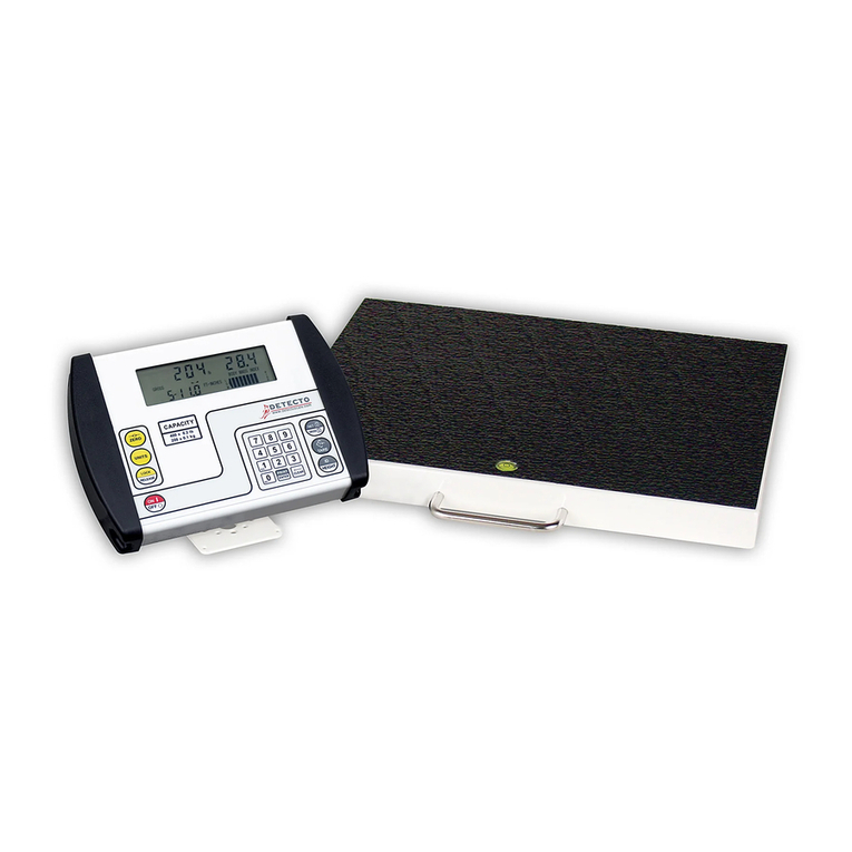
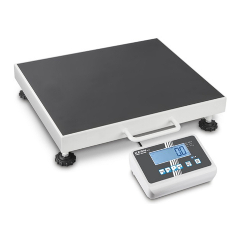
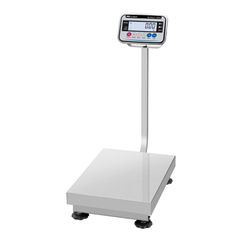
Detecto VET550 User manual

1961-0397-0M ࢂVET550 Owner’s Manual I
VET550 DIGITAL
VETERINARY SCALE
Owner’s Manual

1961-0397-0M ࢂVET550 Owner’s Manual
II

1961-0397-0M ࢂVET550 Owner’s Manual I
PROPER DISPOSAL
When this device reaches the end of its useful life, it must be properly disposed of. It must not
be disposed of as unsorted municipal waste. Within the European Union, this device should be
returned to the distributor from where it was purchased for proper disposal. This is in
accordance with EU Directive 2002/96/EC. Within North America, the device should be
disposed of in accordance with the local laws regarding the disposal of waste electrical and
electronic equipment.
It is everyone’s responsibility to help maintain the environment and to reduce
the effects of hazardous substances contained in electrical and electronic
equipment on human health. Please do your part by making certain that the
device is properly disposed of. The symbol shown to the right indicates that this
device must not be disposed of in unsorted municipal waste programs.
FCC COMPLIANCE STATEMENT
This equipment generates, uses, and can radiate radio frequency and if not installed and used
in accordance with the instruction manual, may cause interference to radio communications. It
has been designed within the limits for a Class A computing device pursuant to Subpart J of
Part 15 of FCC rules to provide reasonable protection against such interference when
operated in a commercial environment. Operation of this equipment in a residential area may
cause interference in which case the user will be responsible for taking whatever measures
necessary to correct the interference.
You may find the booklet "How to Identify and Resolve Radio-TV Interference Problems"
prepared by the Federal Communications Commission helpful. It is available from the U.S.
Government Printing Office, Washington, D.C. 20402. Request stock No. 001-000-00315-4.
COPYRIGHT
All rights reserved. Reproduction or use, without express written permission, of editorial or
pictorial content, in any manner, is prohibited. No patent liability is assumed with respect to the
use of the information contained herein.
DISCLAIMER
While every precaution has been taken in the preparation of this manual, the Seller assumes
no responsibility for errors or omissions. Neither is any liability assumed for damages resulting
from the use of the information contained herein. All instructions and diagrams have been
checked for accuracy and ease of application; however, success and safety in working with
tools depend to a great extent upon the individual’s accuracy, skill, and caution. For this
reason, the Seller is not able to guarantee the result of any procedure contained herein. Nor
can they assume responsibility for any damage to property or injury to persons occasioned
from the procedures. Persons engaging in the procedures do so entirely at their own risk.

1961-0397-0M ࢂVET550 Owner’s Manual
II
TABLE OF CONTENTS
INTRODUCTION . . . . . . . . . . . . . . . . . . . . . . . . . . . . . . . . . . . . . . . . . . . . . . . . . . . . Page 1
SPECIFICATIONS . . . . . . . . . . . . . . . . . . . . . . . . . . . . . . . . . . . . . . . . . . . . . . . . . . . Page 1
FEATURES . . . . . . . . . . . . . . . . . . . . . . . . . . . . . . . . . . . . . . . . . . . . . . . . . . . . . . . . Page 1
SETUP AND INSTALLATION . . . . . . . . . . . . . . . . . . . . . . . . . . . . . . . . . . . . . . . . . . Page 2
Unpacking . . . . . . . . . . . . . . . . . . . . . . . . . . . . . . . . . . . . . . . . . . . . . . . . . . . . . . Page 2
Install the Scale Feet . . . . . . . . . . . . . . . . . . . . . . . . . . . . . . . . . . . . . . . . . . . . . . Page 2
Transporting the Scale . . . . . . . . . . . . . . . . . . . . . . . . . . . . . . . . . . . . . . . . . . . .
.
Page 3
Lowering Scale from Transport Position to Floor . . . . . . . . . . . . . . . . . . . . . . . .
.
Page 3
Lifting Scale from Floor to Transport Position . . . . . . . . . . . . . . . . . . . . . . . . . . . Page 3
Storing the Scale . . . . . . . . . . . . . . . . . . . . . . . . . . . . . . . . . . . . . . . . . . . . . . . . . Page 3
Placing the Weight Display . . . . . . . . . . . . . . . . . . . . . . . . . . . . . . . . . . . . . . . . . Page 4
Wall Mounting the Weight Display . . . . . . . . . . . . . . . . . . . . . . . . . . . . . . . . . . . . Page 4
Interconnections . . . . . . . . . . . . . . . . . . . . . . . . . . . . . . . . . . . . . . . . . . . . . . . . .
.
Page 4
AC Power Adapter . . . . . . . . . . . . . . . . . . . . . . . . . . . . . . . . . . . . . . . . . . . . . . . . Page 4
USB Port . . . . . . . . . . . . . . . . . . . . . . . . . . . . . . . . . . . . . . . . . . . . . . . . . . . . . . . Page 5
Batteries . . . . . . . . . . . . . . . . . . . . . . . . . . . . . . . . . . . . . . . . . . . . . . . . . . . . . . .
.
Page 5
Battery Installation/Replacement . . . . . . . . . . . . . . . . . . . . . . . . . . . . . . . . . . . . . Page 5
KEY FUNCTIONS . . . . . . . . . . . . . . . . . . . . . . . . . . . . . . . . . . . . . . . . . . . . . . . . . . . Page 6
DISPLAY ANNUNCIATORS . . . . . . . . . . . . . . . . . . . . . . . . . . . . . . . . . . . . . . . . . . . Page 7
OPERATION . . . . . . . . . . . . . . . . . . . . . . . . . . . . . . . . . . . . . . . . . . . . . . . . . . . . . . . Page 8
CONFIGURATION . . . . . . . . . . . . . . . . . . . . . . . . . . . . . . . . . . . . . . . . . . . . . . . . . .
.
Page 9
PRINT OUTPUT SETTING DATA FORMAT . . . . . . . . . . . . . . . . . . . . . . . . . . . . . . . Page 11
DISPLAY MESSAGES . . . . . . . . . . . . . . . . . . . . . . . . . . . . . . . . . . . . . . . . . . . . . . . Page 12
CARE AND MAINTENANCE . . . . . . . . . . . . . . . . . . . . . . . . . . . . . . . . . . . . . . . . . . . Page 12
CALIBRATION PROCEDURE . . . . . . . . . . . . . . . . . . . . . . . . . . . . . . . . . . . . . . . . .
.
Page 13
PRECAUTIONS
Before using this instrument, read this
manual and pay special attention to all
"WARNING" symbols:
IMPORTANT ELECTRICAL
WARNING
Serial Number _____________________
Date of Purchase ___________________
Purchased Form ___________________
__________________________________
__________________________________
RETAIN THIS INFORMATION FOR FUTURE USE

1961-0397-0M ࢂVET550 Owner’s Manual 1
INTRODUCTION
Thank you for purchasing our Detecto Model VET550 Digital Veterinary Scale. This manual
will guide you through the setup and operation of your scale. Please read it thoroughly before
attempting to operate this scale and make it available for future reference.
SPECIFICATIONS
FEATURES
xStainless steel enclosure for durability and easy wipe-down cleaning.
xBuilt-in wheels and integral carrying handle for easy transportation of scale to a
new location.
xThe 7.0 ft (2.1 m) cable from the scale base to the display allows for the placement of
the weight display wherever it is easiest to operate the keypad and read the weight.
xIncluded wall mount display bracket and mounting hardware.
xMinimal assembly required (install non-skid feet and mount bracket for weight display).
xScale can be powered by included AC power adapter or 4 AA batteries (not included).
xSelectable Auto Shut-Off feature (up to 5 minutes) turns the scale off when not used.
xZero is established on a power-up routine and maintained by auto-zero circuitry.
xThe HOLD key allows the animal's weight to be retained after leaving the platform.
xUSB Port for transmission of weight data to an EMR (electronic medical record)
software program.
Capacity: 550 lb x 0.2 lb (250 kg x 0.1 kg)
Platform Size: 36 in L x 22 in W x 2 in H (90 cm L x 56 cm W x 51 cm H)
Display Size: 6.8 in L x 1.6 in D x 3.2 in H (17 cm x 4 cm x 8 cm)
Weight Display: Five Digit with decimal, seven-segment, 1.0-inch (25 mm) LCD
Power Requirements: 100 to 240V AC 15V DC 300 mA wall plug-in UL/CUL listed AC
power adapter or 4 AA alkaline batteries (not included)
Construction: Stainless steel
Tare: 100% of scale capacity
Keys: HOLD, UNIT, ON/OFF, TARE
Operating Environment: Temperature Range: 41 to 95 °F (+5 to +35 °C)
Humidity: 35% ~ 90% RH
Net Weight: 40 lb (18 kg)
Shipping Weight: 50 lb (23 kg)

1961-0397-0M ࢂVET550 Owner’s Manual
2
SETUP AND INSTALLATION
Unpacking
Before beginning the installation of your scale, make certain the instrument has been received
in good condition. When removing the scale from its packing, inspect it for signs of damage,
such as exterior dents and scratches. Keep the carton and packing material for return
shipment if it should become necessary. It is the responsibility of the purchaser to file all
claims for any damages or loss incurred during transit. Remove all plastic wrapping, foam
fillers, and cardboard material from the scale platform, display, and other components. You
should have the following components:
(1) Scale Base (with attached Display Cable)
(1) Stainless Steel Platform Cover
(1) Weight Display Wall Mounting Bracket
(1) 15V DC 300 mA AC power adapter
(1) Hardware Pack, containing:
(2) Screws and Plastic Wall Anchors
(4) Non-skid Scale Feet
Install the Scale Feet
IMPORTANT! THE LEVELING FEET MUST BE INSTALLED TO OPERATE
THE SCALE.
1. Remove the four leveling feet from the
shipping pack and install one in each
corner of the bottom of the scale base
assembly.
2. For best results, place the scale on a flat
level surface and adjust the leveling feet
to ensure the scale is sitting level and
does not teeter.
3. The scale is now ready for operation.
Leveling Feet
Leveling Feet

1961-0397-0M ࢂVET550 Owner’s Manual 3
SETUP AND INSTALLATION, CONT.
Transporting the Scale
The VET550 has built-in wheels and an integral carrying handle
for easy transportation of the scale to a new location. Follow the
instructions below to safely lower and raise the scale to and from
the floor when relocating the scale.
DO NOT DROP THE SCALE! This scale weighs
approximately 40 pounds. Damage to the load cells can
occur if the scale is dropped or allowed to fall from the
transport position. If damage to the scale is determined
to have been caused by falling or dropping the scale,
the warranty will be voided!
Lowering Scale from Transport Position to Floor
1. From the transport position, stand close to the scale with your
feet 8 to 12 inches apart.
2. Firmly grasp the handle on the scale.
3. While stepping back, lower the scale to the floor, keeping your
back straight and bending your knees until you are in a
squatting position.
Never bend at the waist with your legs straight!
Lifting Scale from Floor to Transport Position
1. Stand close to the scale with your feet 8 to 12 inches apart.
2. Keeping your back straight, bend your knees until you are in a
squatting position.
Never bend at the waist with your legs straight!
3. Firmly grasp the handle on the scale and lift it straight up. Do
not twist to either side. Keep the scale close to you, not at
arm's length.
4. Use your leg muscles as you lift, keeping your back upright and in its natural posture.
Always lift steadily and smoothly without jerking.
Storing the Scale
For storage, lay the scale flat for maximum protection against damage.
Placing the Scale
The scale should be placed on a flat, level floor or low-cut carpet away from any rapidly
moving air source (heating and cooling vents). Check to make certain the scale is level and
does not teeter. If it is not, adjust all four (4) feet as required to attain a level scale.
NOTE: Any time the scale is moved or re-located, be sure to check if the scale is
level before using it.
Scale Transport Position

1961-0397-0M ࢂVET550 Owner’s Manual
4
SETUP AND INSTALLATION, CONT.
Placing the Weight Display
The VET550 display has a 7.0 ft (2.1 m) cable to allow it to be placed at a convenient position
away from the scale base. The included bracket can be used to mount the weight display on a
wall for easy viewing and operation.
Wall Mounting the Weight Display
1. Choose the location to mount the display
on the wall where it can be easily viewed,
not subject to direct sunlight, and where
the keypad is within easy reach of the
operator.
2. Using the bracket for a template, place the
bracket against the wall and mark the
holes to drill.
3. Remove the bracket and drill two holes in
the wall for the mounting wall anchors.
4. Insert the two wall anchors into the drilled
holes and push them in until they are flush
with the wall.
5. Place the weight display bracket against
the wall aligning the holes in the bracket
with the two wall anchors and insert the
two (2) wall anchor screws through the
bracket and into the wall anchors.
6. Tighten the screws to secure the bracket to the wall.
7. Plug the display cable into the bottom of the weight display and then set the weight display
on the bracket.
Interconnections
Power and output connections to the VET550 Digital Veterinary Scale are made on the right
side (as viewed facing the display) of the weight display. Connections for the scale input are
made using a snap-in modular connector on the bottom of the weight display. The USB port is
a device (or upstream) port using an industry-standard “B” connector. The included 15V DC
wall plug-in UL/CSA listed AC power adapter is connected using a power jack.
AC Power Adapter
To apply power to the VET550 scale using the
supplied 100 to 240V AC 15V DC 300 mA wall
plug-in UL/CUL listed AC power adapter,
insert the plug from the power adapter cable
into the power jack on the right side of the
display and then plug AC power adapter into
the proper electrical outlet.
Use the weight display mounting bracket
as a template to mark the holes to drill.

1961-0397-0M ࢂVET550 Owner’s Manual 5
SETUP AND INSTALLATION, CONT.
USB Port
The USB port on the VET550 Digital Veterinary Scale may be connected to a computer for
transmission of weight data to an EMR (electronic medical record) software program. The
weight data will be transmitted automatically (if selected in Configuration) once the weight is
stable or also selected in Configuration when a weight request from the host computer is
received. For a breakdown of the data format transmitted, refer to the PRINT OUTPUT
SETTING DATA FORMAT section of this manual.
TARE SWITCH
The tare switch is not used on the VET550 Digital Veterinary Scale.
Batteries
The VET550 Digital Veterinary Scale can use (4) AA 1.5V alkaline batteries (not included). If
you wish to operate the scale from batteries, you must first obtain and install the batteries
before operations can begin. Batteries are contained in a battery holder inside the display.
Access is via a removable door on the back of the display.
Battery Installation/Replacement
The VET550 Digital Veterinary Scale operates from four (4) AA batteries. Note that Alkaline
are recommended. To install or replace the batteries, the following steps should be followed:
1. Remove the weight display from the
weight display mounting bracket.
2. Unplug the display cable from the bottom
of the weight display.
3. Place the display face down on a flat
surface.
4. Remove the battery compartment door.
5. When installing new batteries, proceed to
step 6. When replacing the batteries,
remove all four batteries from the battery
holder and then proceed to step 6.
6. Install the four new batteries in the battery holder noting the polarity markings located in the
battery holder.
7. Replace the battery compartment door.
8. Turn the weight display over (display facing up), and then press the ON/OFF key.
9. If the display turns on, the batteries have been installed correctly. If not, remove the battery
compartment door and check for one or more improperly positioned batteries.
10. Plug the display cable into the bottom of the weight display and then set the weight display
on the bracket.
11. The scale is now ready for operation.

1961-0397-0M ࢂVET550 Owner’s Manual
6
KEY FUNCTIONS
ON/OFF
Press and release the ON/OFF key to turn the scale On or Off.
UNIT
Press the UNIT key to change the weighing units to the alternate units of measurement (if
selected during the configuration of the scale).
TARE
1. Press the TARE key to zero the weight display or to Tare the weight of a container (e.g.,
a basket, box, or crate) up to 100% of the scale capacity.
2. Press and hold the TARE key to enter the Configuration mode.
HOLD
1. Press to turn the Hold function On or Off.
2. In the Configuration mode, press to toggle between the settings for each configuration
parameter, and then advance to the next menu.
DO NOT operate the keypad with pointed objects (pencils, pens, etc.). Damage
to the keypad resulting from this practice is NOT covered under the warranty.

1961-0397-0M ࢂVET550 Owner’s Manual 7
DISPLAY ANNUNCIATORS
The display annunciators are turned on to indicate that the scale display is in the mode
corresponding to the annunciator label or that the status indicated by the label is active.
O
This annunciator will be turned on when the weight display is stable.
This annunciator will be turned on when a negative (minus) weight is displayed.
This annunciator will be turned on when the scale weight has been zeroed.
Hold
This annunciator will be turned on after pressing the HOLD key.
NET
This annunciator will be turned on after pressing the TARE key to Tare the weight of a
container (e.g., a basket, box, or crate) on the scale.
kg
This annunciator will be turned on to indicate that the displayed weight is in kilograms.
lb
This annunciator will be turned on to indicate that the displayed weight is in pounds.
!6 (Low Battery)
When the batteries are near the point they need to be replaced, a low battery indicator on the
display will turn on. If the voltage drops too low for accurate weighing, the scale will
automatically shut off and you will be unable to turn it back on. When the low battery indicator
is displayed, the operator should replace the batteries or remove the batteries and plug the AC
power adapter into the scale and then into the proper electrical wall outlet.

1961-0397-0M ࢂVET550 Owner’s Manual
8
OPERATION
DO NOT operate the keypad with pointed objects (pencils, pens, etc.). Damage
to the keypad resulting from this practice is NOT covered under the warranty.
Turn the Scale On
Press the ON/OFF key to turn the scale on. The scale display will show all segments and
then change to the selected weighing units.
Select the Weighing Unit
Press the UNIT key to alternate between the selected weighing units.
NOTE: Multiple weighing units must be enabled during configuration for this function to be
operational.
Weighing an Item
Place the animal to be weighed on the scale platform. Wait a moment for the scale display
to stabilize, then read the weight.
To Zero or Tare the Weight Display
1. To zero the scale display or to tare the weight of a container (e.g., a basket, box, or
crate) on the scale, press the TARE key.
2. If nothing is on the scale when the TARE key is pressed, the scale will zero the weight
display.
3. If a container is on the scale when pressed, the scale will enter the Tare mode and the
NET annunciator will be turned on.
NOTE: This is useful when weighing an animal in a container (e.g., a basket, box, or
crate). To control the total weight, the weight of the container must be retrieved first.
Hold Weight Display
1. To hold the weight on the scale display, press the HOLD key.
2. The scale display will display A on and flash the HOLD annunciator.
3. Place the animal on the scale.
4. When the weight stabilizes, the scale display will show and hold the weight, and the
HOLD annunciator will be steady.
5. Press the HOLD or TARE key to exit the Hold mode.
Turn the Scale Off
With the scale turned on, press the ON/OFF key to turn the scale off.

1961-0397-0M ࢂVET550 Owner’s Manual 9
CONFIGURATION
The VET550 Digital Veterinary Scale has been pre-configured at the factory and should not
require changes to use in most applications. If the factory settings do not meet the
requirements of your application, the following describes the steps to change the configuration
of the scale.
To Begin Configuration:
1. Press the ON/OFF key to turn on the scale.
2. Press and hold the TARE key until the display changes to *4;.
3. Release the TARE key.
4. The display will change to '0-; (Weighing Units).
'"-& (Weighing Units)
The default setting is lb and kg (pounds and kilograms).
To select the desired weighing units:
1. With the display showing '0-;, press the TARE key. The display will change to “kg”.
2. Press the TARE key to show the status of “kg”.
3. Press the HOLD key to toggle between: ON or OFF.
4. Press the TARE key. The display will again show the weighing unit (“kg”).
5. Press the HOLD key to advance the display to “lb”.
6. Press the TARE key to show the status of “lb”.
7. Press the HOLD key to toggle between: ON or OFF.
8. Press the TARE key. The display will again show the weighing unit (“lb”).
9. Press the HOLD key.
10. Proceed to # (Automatic Shutoff).
# (Automatic Shutoff)
The default setting is 120 seconds.
1. With the display showing '0-;, press the HOLD key.
2. The display will change to show #.
3. Press the TARE key to begin the selection of the automatic shut-off time (in seconds).
4. The display will change to show the current setting.
5. Press the HOLD key to toggle through the selections,
:, :, :, :, or #.
6. When the desired time is displayed, press the TARE key.
7. Press the HOLD key.
8. Proceed to 2'99 (Beeper/Buzzer).

1961-0397-0M ࢂVET550 Owner’s Manual
10
CONFIGURATION, CONT.
'%% (Buzzer/Beeper)
The default setting is Buzzer/Beeper Off.
1. With the display showing 1#, press the HOLD key.
2. The display will change to show 2'99.
3. Press the TARE key to show the buzzer/beeper status.
4. Press the HOLD key to toggle between:
Enabled: The display will change to #0.
Disabled: The display will change to #.
5. Press the TARE key.
6. Press the HOLD key.
7. Proceed to 26!(Backlight).
216/(Backlight)
The default setting is Auto.
1. With the display showing '99, press the press HOLD key.
2. The display will change to show 26!.
3. Press the TARE key to show the Backlight status.
4. Press the HOLD key to toggle between ON, OFF, or AUTO.
a. ON: The backlight is always on.
b. OFF: The backlight is always OFF.
c. AUTO: The backlight is only on during weighing.
5. When the desired state is displayed, press the TARE key.
6. Press the HOLD key.
7. Proceed to $*; (Print Output Setting).
$*; (Print Output Setting)
The default setting is Off.
1. With the display showing 26!, press the press HOLD key.
2. The display will change to show $*;.
3. Press the TARE key to show the Print Output Setting status.
4. Press the HOLD key to toggle between <&6 or #.
x<&6: The scale will transmit the data continuously when the weight is stable.
x#: The scale will transmit the data one time after receiving a "P" or "p" command.
5. When the desired state is displayed press the TARE key.
6. Press the HOLD key to proceed to ".
03`
Press the HOLD key to return to the beginning of Configuration or press the TARE key to
exit Configuration and return to normal scale operation.

1961-0397-0M ࢂVET550 Owner’s Manual 11
PRINT OUTPUT SETTING DATA FORMAT
The VET550 Digital Veterinary Scale weight display USB port can be connected to a computer
for transmission of weight data to an EMR (electronic medical record) software program. The
VET550 can be configured to transmit the weight data continuously (when the weight
becomes stable) or one time when receiving a weight request “P” (50h) or “p” (70h) from the
host computer. This is known as Weight-On-Demand. Examples and explanations of the data
format transmitted are shown below.
xIf
<&6 is selected for $*& (Print Output Setting), the scale will transmit the weight
data continuously when the weight becomes stable.
xIf
# was selected for $*& (Print Output Setting), the scale will transmit weight data
one time when receiving a weight request “P” (50h) or “p” (70h) from the host computer.
When the weight is stable or the scale receives a “P” (50h) or “p” (70h) command:
The scale will respond with the following 31-byte weight strings:
Line 1 – Gross Weight
Unit: kg/lb(d)
<GROSS><SP><WEIGHT><SP><SP><SP><SP><SP><SP><W><W><W><W><W><W>
<W><SP><U2><U2><CR><LF><LF>
Unit: lb(f)
<GROSS><SP><WEIGHT><SP><SP><SP><SP><SP><SP><W><W><W><SP><W><S>
<W><SP><U2><U2><CR><LF><LF>
Line 2 – Tare Weight
Unit: kg/lb(d)
<TARE><SP><WEIGHT><SP><SP><SP><SP><SP><SP><W><W><W><W><W><W><W>
<SP><U2><U2><CR><LF><LF>
Unit: lb(f)
<TARE><SP><WEIGHT><SP><SP><SP><SP><SP><SP><W><W><W><SP><W><S><W>
<SP><U2><U2><CR><LF><LF>
Line 3 – Net Weight
Unit: kg/lb(d)
<NET><SP><WEIGHT><SP><SP><SP><SP><SP><SP><W><W><W><W><W><W><W>
<SP><U2><U2><CR><LF><LF>
Unit: lb(f)
<NET><SP><WEIGHT><SP><SP><SP><SP><SP><SP><W><W><W><SP><W><S><W>
<SP><U2><U2><CR><LF><LF>
Line 4 – Spacing Line
<SP><SP><SP><SP><SP><SP><SP><SP><SP><SP><SP><SP><SP><SP><SP><SP>
<SP><SP><SP><SP><SP><SP><SP><SP><SP><SP><CR><LF><LF><LF><LF>
Where:
<SP> = Space 20h (" ")
<W> = Wei
g
ht 30h~39h
(
“0~9”
)
or 20h
(
“ “
)
or 2Dh
(
“-“
)
or 2Eh
(
“.”
)
<U2> = Units 6B 67h (kg) or 6C 62h (lb)
<CR> = Carria
g
e Return 0Dh
<LF> = Line Feed 0Ah
<S> = Slash 2Fh
(
“/”
)
or 20h
(
“ “
)
(
d
)
= Indicates displa
y
with decimal point
(f) = Indicates display with fractions
Examples:

1961-0397-0M ࢂVET550 Owner’s Manual
12
DISPLAY MESSAGES
The VET550 Digital Veterinary Scale is equipped with software that tests various portions of
the scale's circuitry and verifies proper operation. Should a problem be detected, a message
will be displayed alerting the operator to that condition. The following lists the messages
displayed, their meaning, and a possible solution.
MESSAGE MEANING POSSIBLE SOLUTION
!6
The batteries are near the point
where they need to be replaced.
NOTE: If the battery voltage drops
too low for accurate weighing, the
scale will automatically shut off and
you will be unable to turn it back on.
To continue to operate the scale,
replace the batteries or remove the
batteries and plug the AC power
adapter into the scale and then into
the proper electrical wall outlet.
99` This error is displayed when the
weight on the scale exceeds the
scale capacity.
xRemove the weight on the scale to
clear the error and try again.
xMake sure the scale platform is not
touching an adjacent object.
xIf the error continues, please
consult your scale service
representative.
993` This error indicates an analog-to-
digital converter failure and the scale
will turn off in three (3) seconds.
Please consult your scale service
representative.
99`This error indicates a Calibration
mode failure.
Please consult your scale service
representative.
CARE AND MAINTENANCE
The heart of the VET550 Digital Veterinary Scale is four precision load cells located in each
corner of the scale base. It will provide accurate operation indefinitely if protected against
overload of scale capacity, dropping items on the scale, or other extreme shocks.
xDO NOT submerge the scale or display in water, pour or spray water directly on them.
xDO NOT use acetone, thinner, or other volatile solvents for cleaning.
xDO NOT expose scale or display to direct sunlight or temperature extremes.
xDO NOT place the scale in front of heating or cooling vents.
xDO clean the scale and display with a damp soft cloth and mild non-abrasive detergent.
xDO remove the power before cleaning with a damp cloth.
xDO provide clean AC power and adequate protection against lightning damage.
xDO keep surroundings clear to provide clean and adequate air circulation.

1961-0397-0M ࢂVET550 Owner’s Manual 13
CALIBRATION PROCEDURE
This scale was calibrated at the factory and should not require adjustment. In the event the
scale should need recalibration, the following describes the calibration of the VET550 Digital
Veterinary Scale. A qualified technician should perform this function to maintain the
instrument's high degree of accuracy.
Before beginning calibration, the following equipment is required:
200 kg calibrated test weight
To begin calibration:
1. Make certain the scale platform is empty and the scale is off.
2. Press and hold ON/OFF key.
3. Press the UNIT key three times and then release the ON/OFF key.
4. The display will show the raw counts.
5. Press TARE key once, the display shows lb.
6. Place the 200 kg calibrated test weight on the scale.
7. The display shows the span counts.
8. Press TARE key once, and display shows ! then .kg.
9. The calibration is complete and can return to normal weighing operation.

STATEMENT OF LIMITED WARRANTY
Detecto Scale warrants its equipment to be free from defects in material and workmanship as follows: Detecto warrants to the
original purchaser only that it will repair or replace any part of equipment which is defective in material or workmanship for a
period of two (2) years from date of shipment. Detecto shall be the sole judge of what constitutes a defect.
During the first ninety (90) days Detecto may choose to replace the product at no charge to the buyer upon inspection of the
returned item.
After the first ninety (90) days, upon inspection of the returned item, Detecto will repair or replace it with a remanufactured
product. The customer is responsible for paying for the freight both ways.
This warranty does not apply to peripheral equipment not manufactured by Detecto; this equipment will be covered by certain
manufacturer’s warranty only.
This warranty does not include replacement of expendable or consumable parts. This does not apply to any item which has
deteriorated or damaged due to wear, accident, misuse, abuse, improper line voltage, overloading, theft, lightning, fire, water or
acts of God, or due to extended storage or exposure while in purchaser’s possession. This warranty does not apply to maintenance
service. Purchased parts will have a ninety (90) day repair or replacement warranty only.
Detecto may require the product to be returned to the factory; item(s) must be properly packed and shipping charges prepaid.
A return authorization number must be obtained for all returns and marked on the outside of all returned packages.
Detecto accepts no responsibility for items lost or damaged in transit.
Conditions Which Void Limited Warranty
This warranty shall not apply to equipment which:
A.) Has been tampered with, defaced, mishandled or has had repairs and modifications not authorized by Detecto.
B.) Has had serial number altered, defaced, or removed.
C.) Has not been properly grounded according to Detecto’s recommended procedure.
Freight Carrier Damage
Claims for equipment damaged in transit must be referred to the freight carrier in accordance with freight carrier regulations.
This warranty sets forth the extent of our liability for breach of any warranty or deficiency in connection with the sale or use of
the product. Detecto will not be liable for consequential damages of any nature, including but not limited to, loss of profit, delays
or expenses, whether based on tort or contract. Detecto reserves the right to incorporate improvements in material and design
without notice and is not obligated to incorporate improvements in equipment previously manufactured.
The foregoing is in lieu of all other warranties, express or implied including any warranty that extends beyond the description of
the product including any warranty of merchantability or fitness for a particular purpose. This warranty covers only those Detecto
products installed in the forty-eight (48) contiguous continental United States.
08/27/2014
Printed in USA
D268-WARRANTY-DET-A
Ph. (800) 641-2008
E-mail: [email protected]
203 E. Daugherty
Webb City, MO 64870

1961-0397-0M ࢂVET550 Owner’s Manual 15

1961-0397-0M ࢂVET550 Owner’s Manual
16
1961-0397-0M Rev A 09/23
Cardinal Scale Manufacturing Co.
102 E. Daugherty, Webb City, MO 64870 USA
Ph: 417-673-4631 or 1-800-641-2008
Fax: 417-673-2153
Technical Support: 1-866-254-8261
E-mail: tech@cardet.com
Table of contents
Other Detecto Scale manuals
Detecto
Detecto 6880 User manual
Detecto
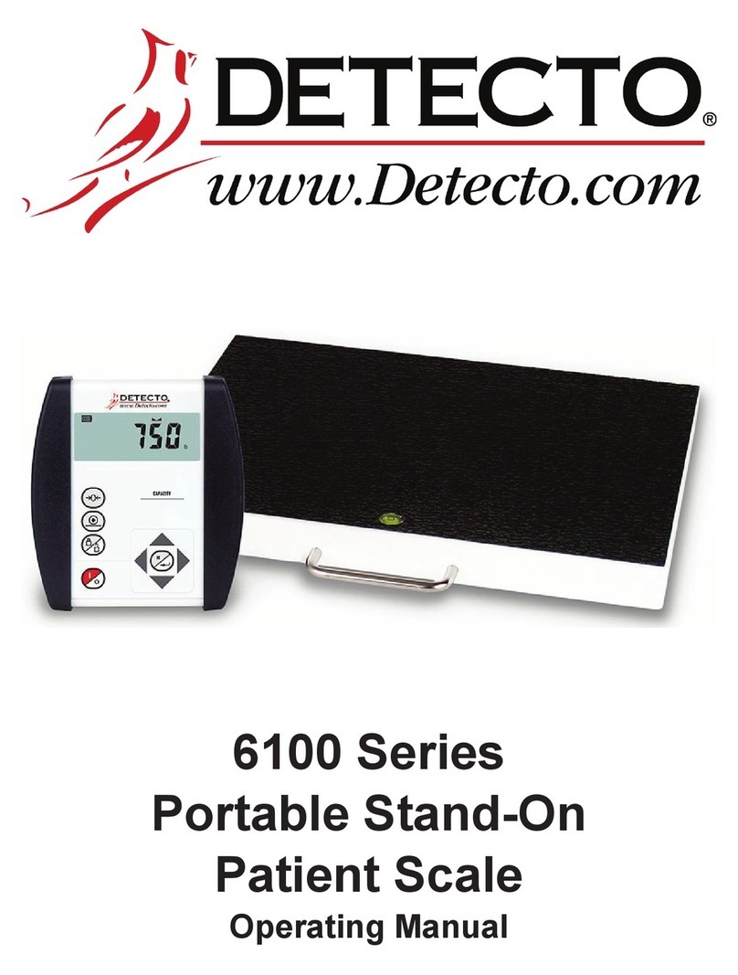
Detecto 6100 Series User manual
Detecto
Detecto 8463 User manual

Detecto
Detecto 6876 User manual
Detecto
Detecto WeighRite W200 Series User manual
Detecto
Detecto 685 Series User manual

Detecto
Detecto MS-1600 User manual
Detecto
Detecto 750 User manual
Detecto
Detecto D121 User manual

Detecto
Detecto Solace ID-3636S-855RMP User manual
Detecto
Detecto PL600 User manual

Detecto
Detecto 6856 User manual
Detecto
Detecto APEX-RI User manual
Detecto
Detecto D217 User manual
Detecto
Detecto D118 User manual
Detecto
Detecto 8435 User manual
Detecto
Detecto 6475 User manual
Detecto
Detecto 750 User manual
Detecto
Detecto IB400 User manual
Detecto
Detecto 337 User manual


