Detex 800 Series User manual
Detex Corporation, 302 Detex Drive, New Braunfels, Texas 78130-3045
(830)629-2900 / 1-800-729-3839 / Fax (830)620-6711
E-MAIL: [email protected] INTERNET: www.detex.com
101339 November 16, 2011
INSTRUCTIONS FOR 81-800
Owner's Copy
101339 Page 1
Indicator turns green when operator
signal is active
Terminals are connected
to a SPDT dry contact relay
Terminal 14 is common
Terminal 13 is normally closed
Terminal 15 is normally open
Door Operator Signal and Indicator
PWA 102879 El ectronic Latch Retraction Controller
I/O and Quick Reference Operating Information
Door Operator Signal Delay
Door operator signal is triggered
after latch retraction and time is
adjustable from 0.5 to 3 seconds.
Operator signal delay time
differential is adjusted by R21
Turn CW to increase delay time
Use a normally open dry contact switch,
close to operate. Terminals are electrically
equivalent.
Important: Observe Polarity when connecting
output wires
Door 2 Out
Indicator turns red
when door is active
Door Outputs
Door 2 Power
+
9
Two Door
Systems Only
12
Door 1 Out
J2
11
+
10
-
J3
Door 1 Power
-
Door Differential Delay
Important: Differential time is
factory set and should not require
adjustment. Adjust for special
circumstances only. Door actuation
time differential is adjusted by R5.
Turn CW to increase differential time.
R5
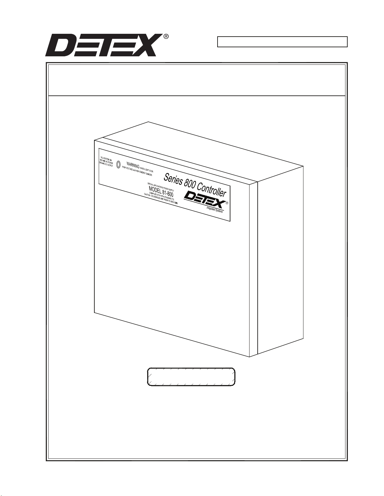
DETEX Model 81-800
Connection Diagram and Instructions
The 81-800 is a regulated and filtered power supply.
It has a selectable output voltage of either 12 or 24 volts DC.
For Detex systems always select 24 volts DC.
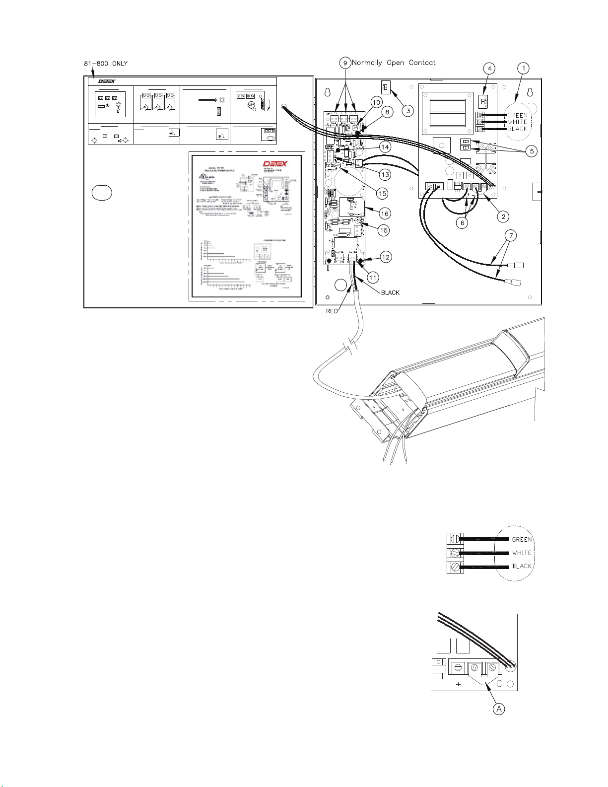
Refer to the drawing of the power supply/controller for connections
and adjustments. All connections and adjustment must be made with
the power supply de-energized AND main power switch (item 3) in
the OFF position.
1: Main power connection. Observe correct terminal connections. Color
code requires connections made per NFPA72. Leave circuit
de-energized while installing and servicing unit.
2: Fire loop control. The fire loop control is bypassed with a factory
jumper. This allows the unit to operate independently and does not
require any external connections to operate. If connections to the
building fire alarm system are required, remove jumper plate A between
the (-) and (C)terminals. Connect the two wires from the building fire
system to these terminals. The power supply will operate normally as
long as the connection between the (-) and (C) is maintained. When the
building fire alarm system opens the circuit, the power supply
de-energizes the output voltage. Fire loop uses 24 volt sense voltage.
Door Hold Select
Latch retraction hold time is adjusted by R13
Turn CW to increase hold time up to 30
seconds
Q6
Input 3 R13
Increase
Hold
Time
PWA 102879
D11
7 8
Input 3
5 6
Typical Single Door
Installation
81-800
Diff.
Adj.
Model 81-800 Regulated Power Supply
Green when power is good
Power Indicator
3 4
Input 1
5 6
Input 2
7 8
Input 3
N.O.
Switch
Input 2
Control Inputs
5 63 4
N.O.
Switch
Input 1
N.O.
Switch
Input 3
7 8
Optional 12 Volt Supply Module
Optional 12 volt supply
module plugs onto P1
and P2. Plug is keyed for
alignment, do not force.
Order DETEX catalog
number: 12M
R21
Door Signal
Delay Adjust
300 mA max
P1
P2
Label P/N 103521-2 Rev 01 05/25/05
13
15
14
N.O.
com
N.C.
Door Signal
101339 Page 2
3: Main ON-OFF switch. This switch can be used to de-energize the
power supply for service and adjustments. High voltage is still present
inside the enclosure as long as the main power feed is energized, so
caution should still be used when service is performed using this switch.
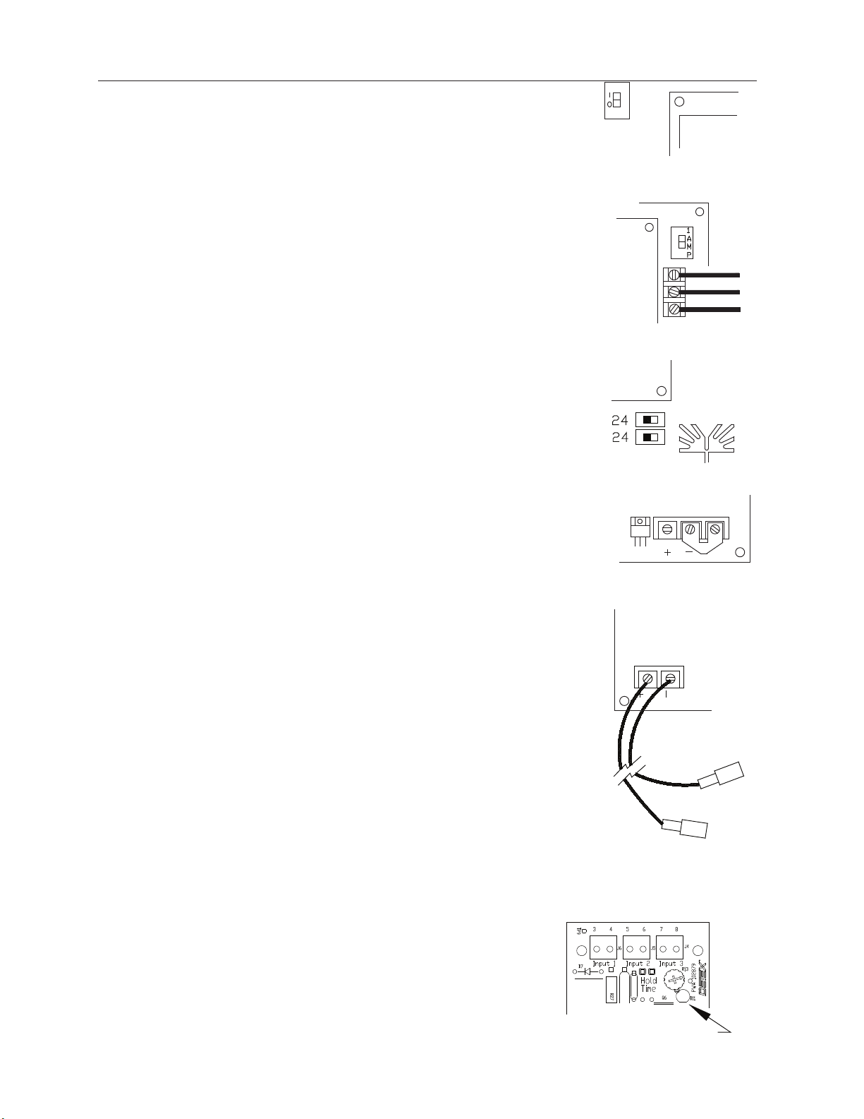
4: 1 Amp circuit breaker. This is intended to protect the device against
high current loads and is part of the AC input circuit. It is a thermal
device and can be reset once the cause of the overload is corrected.
5: Output voltage select switches. These must both be set to the 24 volt
position. They should be preset at the factory and require no adjustment.
If they need adjustment, de-energize the unit first.
6: Output terminals. Outputs 24 volts at 1 amp maximum. The output is
protected by a PTC thermally resetable fuse element. The fuse will reset
once the cause of the overload is found and corrected. Observe correct
polarity when making connections. Factory wired to ER control board.
7: Optional battery backup connections. This output is intended for lead
acid batteries and is also at 24 volts. Typically, two 12 volt batteries are
connected in series for this application. Approximate battery life is
charted on the label inside the cover of the power supply.
Power Indicator
Green when power is good
8: Power Good Indicator. This LED will glow green if 24 volts is
supplied to the controller board.
101339 Page 3

R5
Diff.
Adj.
Door operator signal is triggered
after latch retraction and time is
adjustable from 0.5 to 3 seconds
Operator signal delay time
is adjusted by R5.
Turn CW to increase delay time
if R21 does not supply enough
delay
Indicator turns green when operator
signal door is active
Door Operator Signal and Indicator
Door Signal
Terminal 14 is common
Terminal 13 is normally closed
Terminal 15 is normally open
Terminals are connected
to a SPDT dry contact relay
13
15
14
N.C.
N.O.
com
Control Inputs
7 83 4 5 6
Input 1
N.O.
Switch
N.O.
Switch
Input 2
N.O.
Switch
Input 3
Door Hold Select
Increase
Door Outputs
Two Door
Systems Only
Door 1 OutDoor 2 Out
Door 2 Power
9
+
J3
Indicator turns red
when door is active
10
-+
1211
J2
Door 1 Power
-
com
14
15 N.O.
Door Signal
Indicator turns green when operator
signal door is active
Door Operator Signal and Indicator
13 N.C.
Door Operator Signal Delay
Door Signal
Delay Adjust
R21
9: Control Inputs. These require a normally open contact.
The door latch will activate and hold once the circuit between
the terminals of Inputs 1 (J6) , 2 (J5) or 3 (J4) is closed.
10: Door Hold Delay Adjust. This potentiometer adjusts the length of
time the latch is held retracted once the input switch is released.
Turn clockwise to increase the latch hold time up to a maximum
of about 30 seconds.
11: Output to ER Device. This terminal block (J2) is connected
to the ER power wires. Observe correct polarity. Red from the ER
is positive (terminal 11) and black is negative (terminal 12). The
board is also marked + and - at the connections as well.
12: Door Output Activity Indicator. The LED glows red
when the output voltage to the latch retraction device is energized.
13: Door Opener Output. Connector J7 is connected to
a relay. It can be used to signal a door opener or other
device that the latch is retracted. It is delayed and goes
active after the latch retraction occurs. The amount of the
delay is .5 to 3 seconds and is adjusted by Item 15 below.
14: Door Operator Status Indicator. The status LED will
glow green when the relay is energized.
15: Door Operator Delay Adjust. There are two potentiometers
that adjust the delay of the operator signal relay. Under normal
use, only R21 should be used. Turn clockwise to increase the
delay between the door latch retraction and the relay being
energized. Turn R5 only if a longer delay time is needed.
101339 Page 4

P2
Optional 12 Volt Supply Module
Optional 12 volt supply module
plugs onto P1 and P2. Plug is
keyed for alignment, do not
force. Order DETEX catalog
number: M12
300 mA max
P1
16: Optional 12 Volt Power Module. An optional 12 volt
power supply module is available where a 12 volt DC
source is needed in addition to 24 volts. See the kit
instructions for more information.
RECOMMENDED WIRE SIZES:
WIRE GAUGE MAXIMUM LENGTH OF
TWO CONDUCTOR CABLE
20 AWG 10 FEET
18 AWG 40 FEET
16 AWG 60 FEET
14 AWG 100 FEET
101339 Page 5
This manual suits for next models
1
Table of contents


