1-7
Before appl
in
power to the suppl
, check the label on the
heat sink to make certain that the suppl
's line volta
e option
a
rees with the line volta
e to be used. If the option does not
correspond to
our line volta
e, refer to para
raph "LINE
VOLTAGE OPTION CONVERSION" in the service section
before appl
in
power.
TURN -ON CHECKOUT PROCEDURE
a. Connect line cord to power source and turn LINE
switch on.
b. Push +6V METER switch and, with no load con-
nected, var
+6V VOLTAGE control over its ran
e
and check that the voltmeter responds to the control
settin
and the ammeter indicates zero.
c. Set the +6V VOLTAGE control to 6 volts and short the
+6V output terminal to COM (common) terminal
with an insulated test lead. The ammeter should
indicate a short-circuit output current of approximatel
1.0 A. Remove the short from the output terminals.
d. Push the +20V METER switch and turn Trackin
Ratio control full
clockwise to the Fixed position.
With no load connected, var
±20V VOLTAGE control
over its ran
e and check that the voltmeter
responds to the control settin
and the ammeter indi-
cates zero.
e. Set the ±20V VOLTAGE control to 20 volts and
short the +20V output terminal to the COM terminal
with an insulated test lead. The ammeter should
indicate a short-circuit output current of 0.55 A ± 5%.
Remove the short from the output terminals.
f. Repeat steps (d) and (e) for -20 V output.
. Adjust the +20V output to 20 volts. Then push -20V
METER switch and check the effect of the Trackin
Ratio control on the volta
e of the -20V output. The -
20V output should be adjustable from less than 0.5
volts to a maximum of 19 to 21 volts.
If this brief checkout procedure or later use of the suppl
reveals a possible malfunction, see the service information
section for detailed test, troubleshootin
, and adjustment pro-
cedures.
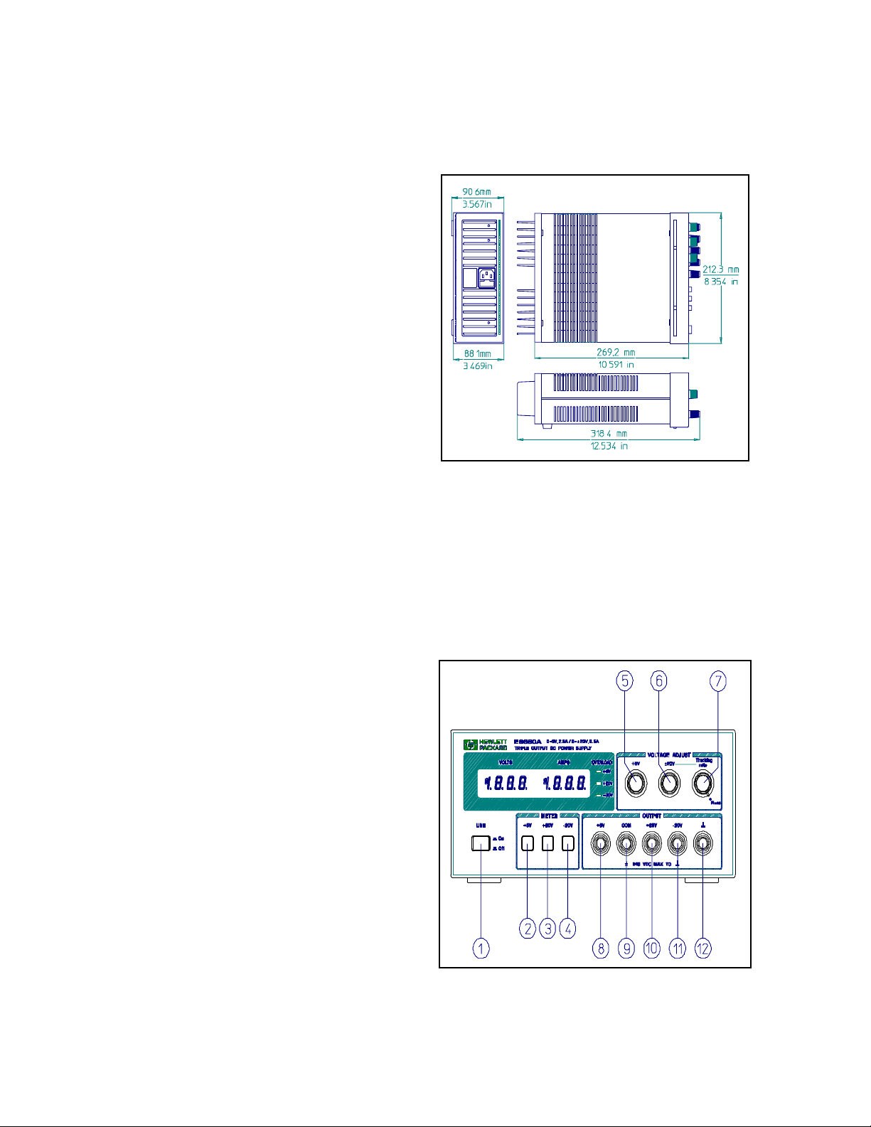
OPERATION
This power suppl
can be operated individuall
or in parallel
or series with another suppl
(see Parallel and Series Opera-
tion para
raphs). All output terminals are isolated from
round. The ±20V and +6V outputs use a sin
le common out-
put terminal. This common (COM) terminal or an
one of the
other output terminals ma
be
rounded to the chassis at the
front panel
round terminal ( in Fi
ure 2), or all outputs ma
be left floatin
. Loads can be connected separatel
between
each of the 0 to ±20V output terminals and the COM terminal,
or between the -20V and the +20V terminals for a 0 to 40V
output. Each output volta
e or current can be quickl
selected
for monitorin
with the push-button meter switches. To moni-
tor the 0 to 40V output volta
e, add the voltmeter readin
s of
the +20V and -20V output and use either the +20V or the -
20V meter to measure the current.
Tracking Ratio Control
With the Trackin
Ratio control in the Fixed position, the volt-
a
e of the -20V suppl
tracks that of the +20V suppl
within
1% for convenience in var
in
the s
mmetrical volta
es
needed b
operational amplifiers and other circuits usin
bal-
anced positive and ne
ative inputs.
Turn the Trackin
Ratio control counter clockwise out of the
Fixed position to set the volta
e of the -20V suppl
lower than
that of the +20V suppl
. The ne
ative suppl
can be set from
a minimum of less than 0.5 volts to a maximum within 5% of
the +20V suppl
's output. Once this is done, the ±20V volta
e
control still controls both outputs and maintains a constant
ratio between their volta
es.
Overload Protection Circuits
±20-Volt Current Limit. The +20V and -20V outputs are indi-
viduall
protected a
ainst overload or short circuit dama
e b
separate current limit circuits to limit the output current to 0.55
A ± 5%. (This is 110% of the maximum rated output.) If a sin-
le load is connected between the +20V and -20V outputs,
the circuit set for the lesser current limit will limit the output.
No deterioration of suppl
performance occurs if the output
current remains below the current limit settin
.
+6V Current Foldback. The overload and short-circuit pro-
tection circuit for the +6V output reduces the output current
limit as the output terminal volta
e decreases. (The operatin
re
ion of the +6V output is enclosed b
heav
lines in Fi
ure
4.) The maximum rated output current is 2.5 A and the current
limit is factor
-adjusted to operate at 2.75 A ± 5% when the
output is 6 volts. At lower output volta
es, the circuit reduces
the maximum obtainable output current linearl
until 1 A ±
15% flows when the output is shorted. The short-circuit cur-
rent can not be adjusted.
Durin
the actual operation of the ±20V and +6V outputs, if a
load chan
e causes the current limit to be exceeded, the OL
LED is li
hted. If overload conditions occur, the ±20V supplies
will protect the load b
limitin
the current to 0.55 A and the
+6V suppl
will protect the load b
reducin
both volta
e and
current simultaneousl
alon
the foldback locus as shown in
Fi
ure 4. The ±20V and +6V supplies are self restorin
; that
is, when the overload is removed or corrected, the output
volta
e is automaticall
restored to the previousl
set value.
Operation Beyond Rated Output
The suppl
ma
be able to provide volta
es and currents
reater than its rated maximum outputs if the line volta
e is at
or above its nominal value. Operation can be extended up to
5% over the rated output without dama
e to the suppl
, but
performance can not be
uaranteed to meet specifications in