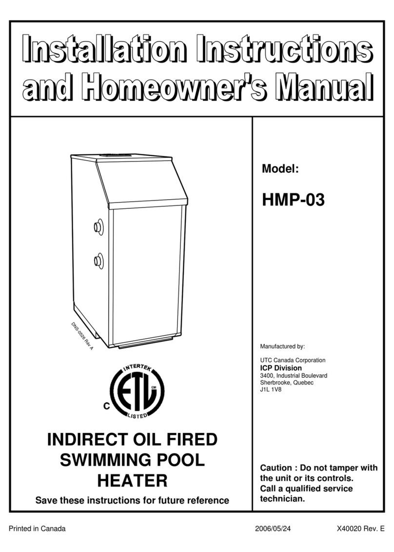
Dettson HMP-03 Assembly instructions

CHAUFFE-PISCINE
(TYPE INDIRECT)
AU MAZOUT
Imprimé au Canada
Conservez ce manuel pour références ultérieures.
Attention : Ne pas altérer
votre unité ou ses contrôles.
Appeler un technicien
qualifié.
HMP-03
Modèles:
DNS-0526RévA
04/02/16 X40020 Rév. D
Fabriqué par :
Division ICP
UTC Canada Corporation
Sherbrooke, Québec J1L 1V8
3400, boulevard Industriel

3
SECTION 1
INSTALLATION
1.1) DANGER, MISE EN GARDE ET
AVERTISSEMENT
Comprenez bien la portée des mots suivant : DANGER, MISE EN
GARDE ou AVERTISSEMENT. Ces mots sont associés aux symboles
de sécurité. Vous les retrouverez dans le manuel de la façon suivante :
DANGER
Le mot DANGER indique les plus graves
dangers, ceux qui provoqueront des blessures
corporelles sérieuses ou la mort.
MISE EN GARDE
L’expression MISE EN GARDE signifie un danger qui
peut entraîner des blessures corporelles ou la mort.
AVERTISSEMENT
Quant au mot AVERTISSEMENT, il est utilisé pour
indiquer les pratiques dangereuses qui peuvent
provoquer des blessures corporelles mineures ou des
dommages à l’appareil ou à la propriété.
Votre chauffe-piscine doit être installe par un technicien
qualifie.
AVIS IMPORTANT
Avec le chauffe piscine HMP-03, ICP (Canada) redéfinit
la notion du chauffe-piscine en proposant un appareil
simple d’utilisation et ultra puissant. Cette puissance
accrue provient d’un échangeur de chaleur au design
unique couplé à un brûleur à huile à haute efficacité.
L’eau de votre piscine atteindra rapidement la
température désirée sans égards aux conditions
climatiques ambiantes. Vous n’avez pas à garder le
chauffe piscine en opération lorsque vous ne comptez
pas vous servir de votre piscine. Nous vous invitons à
utiliser cet appareil selon vos besoins et ainsi éviter des
dépenses inutiles.
Profitez pleinement de la puissance du HMP-03 en
l’utilisant lorsque requis seulement.
AVERTISSEMENT
LA GARANTIE DE VOTRE CHAUFFE-PISCINE SERA NULLE SI LES PROPRIÉTÉS DE L’EAU DE
DE VOTRE PISCINE NE RESPECTENT PAS EN TOUT TEMPS LES NORMES SUIVANTES :
CHLORE : 3.0 ppm MAX PH : 7.2 à 7.5
DURETÉ CALCIQUE : 300 ppm MAX ALCALINITÉ TOTALE : 80 à 120 ppm
UN NIVEAU ÉLEVÉ DE DURETÉ CALCIQUE ET / OU D’ALCALINITÉ PEUT CAUSER DES INCRUSTATIONS SUR
LES MURS DE LA PISCINE ET DANS LE CHAUFFE-PISCINE. SI LE NIVEAU DE DURETÉ CALCIQUE ATTEINT
PLUS DE 300 ppm. LA PISCINE DOIT ÊTRE VIDÉE SUFFISAMMENT ET REMPLIE À NOUVEAU AVEC DE L’EAU
DOUCE AFIN D’OBTENIR UNE DURETÉ CALCIQUE ACCEPTABLE. LE CALCIUM NE S’ÉVAPORANT PAS, IL
S’ACCUMULE AVEC CHAQUE REMPLISSAGE DE LA PISCINE.
!
!

4
1.2) LIVRAISON
Vérifiez attentivement le contenu du chauffe-piscine lors de la livraison
afin de détecter tout dommage ayant survenu durant le transport ou la
manutention de celui-ci. Toutes les réclamations pour dommages ou
matériel manquant doivent être faites directement à la compagnie de
transport.
1.3) INSTALLATION
Votre unité doit être installée selon les règlements des autorités
compétentes. Référez-vous aux codes d'installation CSA B139 et aux
codes électrique Canadien CSA C22.10.
Ce chauffe-piscine peut être installé selon une des options suivantes :
a) A l'extérieur ;
b) A l'intérieur, avec évacuation par une cheminée ;
1.3.1) Installation extérieure
1.3.2) Emplacement
Le chauffe-piscine doit être installé à un endroit propice afin d’éviter les
accumulations d'eau, et ce en tout temps de l'année. Il doit être monté
sur une base solide, stable et de niveau ayant les dimensions
minimales suivantes : 24 po. X 32 po. X 2 po. d'épaisseur. Les
conséquences du renversement du chauffe-piscine dû au dégel
doivent être adressées. L'installateur a donc la responsabilité de
prévenir les accumulations d'eau à proximité de l’appareil à toute
période de l'année en s'assurant d'un drainage adéquat et / ou en
surélevant la base de l'unité et / ou par toute autre façon adéquate.
1.3.3) Dégagements
Les dégagements minimums suivants doivent être respectés :
a) Le diffuseur d'évacuation du chauffe-piscine ne doit pas être situé
à moins de 6 pieds de :
- entrée d'air de tout édifice;
- porte;
- fenêtre;
- régulateur de gaz;
- ligne de propriété.
b) Le diffuseur d'évacuation du chauffe-piscine ne doit pas être situé
à moins de 3 pieds d'un réservoir au mazout ou du tuyau de
remplissage de celui-ci;
c) Le diffuseur d'évacuation du chauffe-piscine ne doit pas être situé
sous une véranda, plate-forme ou tout matériau combustible.
Dégagements de l'enceinte globale du cabinet :
- Coté gauche et Avant : 24 pouces;
- Côtés droit et Arrière: 9 pouces;
- Plancher: Non-Combustible;
- De la paroi de piscine la plus près: 10 pieds.
1.3.4) Installation du diffuseur d'évacuation
extérieur
L'unité HMP-03 doit être installée avec le diffuseur d'évacuation
extérieure "GDK" fabriqué par ICP (Canada) selon les instructions
suivantes (voir figure 2) :
1. Enlevez le recouvrement du tuyau d'évacuation (partie-F) et le
panneau supérieur du chauffe-piscine (partie G);
2. Insérez le tuyau d'évacuation de 6 pouces de diamètre dans le
collet du tuyau à fumée et alignez les trous pré-perforés. Vissez
en place à l'aide des 4 vis à métal fournies dans l'ensemble
(partie-B);
3. Réinstaller le panneau supérieur du chauffe-piscine (partie G);
4. Glissez la gaine extérieure (partie-C) par-dessus le tuyau
d'évacuation (partie-A) et assurez-vous que la gaine soit bien
assise sur le dessus du collet intégral du chauffe-piscine
(partie G);
5. Installez le diffuseur (partie-D) sur la gaine extérieure avec les 8
supports à l'intérieur et alignez le trou du diffuseur avec celui sur
le disque supérieur du tuyau d'évacuation;
6. Vissez le diffuseur sur le disque supérieur avec la vis fournie à cet
effet (partie-E).
1.4) INSTALLATION INTÉRIEURE AVEC
ÉVACUATION DANS UNE CHEMINÉE
1.4.1) Emplacement
Le chauffe-piscine doit être installé dans un endroit propre, le plus près
possible de la cheminée.
ATTENTION
Les produits chimiques tel que le chlore, le brome
ou tout autres produits chimiques volatile et
corrosif doivent être entreposés dans une autre
pièce à l’écart du chauffe-piscine. Le non respect
de cette instruction invalide votre garantie et peut
provoquer une oxydation prématurée de votre
chauffe-piscine.
1.4.2) Dégagements
Les dégagements minimums suivants doivent être respectés :
- Coté gauche et Avant : 24pouces;
- Coté droit et Arrière : 9 pouces;
- Tuyau à fumée : 9 pouces;
- Plancher : Non-combustible;
- De la paroi de piscine la plus près: 10 pieds.
1.5) CÂBLAGE ET RÉGULATEURS
L'installateur doit brancher l'unité selon le diagramme électrique
approprié. Tous les raccordements doivent être faits selon la norme
CSA C22.10, plus particulièrement la section 68.

5
ATTENTION
Avant de choisir une localisation appropriée,
assurez-vous que le chauffe-piscine est au moins à
10 pieds de la paroi de piscine la plus proche. De
plus, si le chauffe-piscine n'est pas séparé de la
piscine elle-même par une clôture ou un mur, vous
devez fournir un disjoncteur différentiel (Classe A)
sur le circuit d'alimentation.
1.5.1) Installation extérieure ou intérieure avec
évacuation dans la cheminée
Tous les contrôles, appareils de sécurité ainsi que le brûleur à mazout
sont montés et brochés en usine. Une alimentation électrique adéquate
pour 115 Volts, 60 Hertz, simple phase, moins de 12 Amps doit être
fournie selon les codes et réglementations applicables. Pour les
branchements, voir la figure 4.
1.6) INSTALLATION ET RACCORDE-MENT DU
RÉSERVOIR A MAZOUT
Le réservoir à mazout doit être installé selon les règlements locaux et la
norme CSA B139. Le brûleur peut être branché à l'aide d'un système à
un ou deux tubes. Nous recommandons l'utilisation d'un système à
deux tubes si le niveau du brûleur est plus haut que le bas du réservoir
à huile. Le brûleur est monté en usine pour un système à un tube.
Veuillez référer aux instructions du manufacturier de la pompe à
mazout pour la conversion à un système à deux tubes si désirée.
L'installation doit inclure un réservoir à mazout certifié, un évent, un
indicateur de niveau, un sifflet de remplissage, une vanne de fermeture
et un filtre d’une capacité d’élimination de 10 microns. Assurez-vous
qu'il n'y a pas de fuites ou obturations sur les conduites. N'utilisez
jamais de raccords de compression. Utilisez des conduites de même
diamètre pour le retour et l'alimentation et positionnez les à la même
profondeur dans le réservoir lorsqu'un système à deux tubes est
employé. Des informations additionnelles sont disponibles dans la
brochure de la pompe à mazout fournie avec le brûleur.
Au début de chaque saison de chauffage ou chaque année, vérifier le
système de distribution d’huile au complet pour la présence de fuite.
1.7) ÉVACUATION DES GAZ DE COMBUSTION
Le tirage de la cheminée doit être suffisant pour assurer un
fonctionnement sécuritaire et adéquat de votre unité.
1.7.1) Cheminée
Le tirage minimal recommandé est de 0.02 " W.C. Les dimensions
minimales et maximales du tuyau d'évacuation (cheminée ou doublure
de cheminée) sont respectivement de 5 et 7 pouces. Le tuyau de
raccordement entre le chauffe-piscine et le tuyau d'évacuation doit être
d'un diamètre de 6 pouces.
Le diamètre du tuyau de raccordement ne doit jamais excéder celui de
la cheminée. L'utilisation d'un registre dans le tuyau de raccordement
est strictement interdite. Si plus de 1 tuyau est branché sur la même
cheminée, la surface de la cheminée doit être égale à la somme des
surfaces de chacun des tuyaux de raccordements. L'utilisation d'un
régulateur de tirage de 6 pouces de diamètre est obligatoire lorsque
l'évacuation se fait par une cheminée. Le non respect de cette clause
peut entraîner l'annulation de la garantie de l'unité.
1.7.2) Évent GDK pour installation extérieur
Avec l’installation de l’ensemble pour évacuation GDK l’installation d’un
régulateur de tirage n’est pas requise. Une lecture de pression
au-dessus du feu ne doit pas normalement être supérieure à + 0.045’’
eau après cinq minutes de fonctionnement.
1.8) INFORMATIONS RELATIVES AU BRÛLEUR
Le brûleur à mazout est monté et broché en usine. Le gicleur est de
plus installé mais l'ajustement des registres d'air doit être fait par le
technicien. Le brûleur est monté en usine pour un système
d'alimentation en mazout à un tube. Veuillez référer à la section 1.6
pour un système à deux tubes.
1.9) ALIMENTATION EN AIR DE COMBUSTION
Toute unité au mazout, pour fonctionner correctement, doit posséder
une alimentation adéquate et fonctionnelle d'air de combustion. Si le
chauffe-piscine est installé dans un espace fermé, 2 ouvertures
permanentes d'alimentation d'air doivent être installées. Une doit être
près du plafond et l'autre près du plancher. Chacune de ces ouvertures
doit être dimensionnée pour permettre 1 pouce carré par 1000 BTU/H
de puissance de sortie (Output).
1.10) TUYAUTERIE
Le chauffe-piscine HMP-03 a été conçu de façon à ce que sa restriction
totale à l'écoulement de l'eau ne soit pas supérieure à plus de 10 pieds
équivalents de tuyau de 1 1/2" . Le débit total d'eau de votre pompe de
piscine va donc s'écouler facilement de votre filtreur jusqu'au chauffe-
piscine. Une voie de contournement n'est pas requise. Vous devez
utiliser du tuyau de plastique de 1 1/2" approuvé pour une température
de 140° F (60oC) entre la sortie du chauffe-piscine et l'entrée de la
piscine elle-même. Les raccordements d'entrée et de sortie du chauffe-
piscine sont conçus pour des raccords filetés mâle de 1 1/2" de
diamètre. Veuillez référer à la figure 3 pour l'emplacement des raccords
d'entrée et de sortie du chauffe-piscine et des autres équipements. Un
distributeur automatique de produit chimique doit être être localisé
entre la sortie d’eau du chauffe piscine et la piscine.
Nous recommandons l'installation de vannes d'entretien plein débits
sur les tuyaux d'entrée et de sortie du chauffe-piscine. Ces vannes sont
requises si le niveau du chauffe-piscine est sous le niveau de l'eau de
la piscine. Toute la tuyauterie ainsi que les accessoires utilisés dans
l'installation du chauffe-piscine doivent être protégés contre la
corrosion. Nous recommandons l'utilisation de 2 collets de serrage en
acier inoxydable sur chaque joint de tuyau flexible de plastique.
TABLEAU 1
Caractéristiques du brûleur
Modèle Input
(Btu/hr)
Output
(Btu/hr)
Input
(USGPH)
Brûleur
Beckett Gicleur Pression
(PSI)
HMP-03 198,000 168,000 1.42 AFG-MD-V1 1.20-60°B 140

6
SECTION 2
OPÉRATION ET ENTRETIEN
Nous recommandons qu'un technicien qualifié
et responsable démarre et entretienne votre
unité. Assurez-vous que le chauffe-piscine et la
tuyauterie sont remplis d'eau avant de
démarrer l'unité.
2.1) COMBUSTIBLE
Utilisez uniquement du mazout #2. Ne jamais utiliser de mazout plus
lourd, de gazoline, d'huile à moteur ou tout autre type de combustible
dans le chauffe-piscine.
2.2) DÉMARRAGE
Le brûleur à mazout de l'unité HMP-03 est assemblé, monté et broché
en usine (gicleur compris). La pression de la pompe est aussi ajustée
en usine à 140 PSI. Les ajustements d'air faits en usine sont les
suivants : 2 pour la bande d'air principale (grosse) et 8 pour la bande
d'air fine (petite). L'assemblage de gicleur est barré de façon
permanente à 0. Le démarrage doit se faire comme suit (Référer à la
figure 1):
1. Assurez-vous que le réservoir à mazout est plein et que sa vanne
de fermeture est ouverte;
2. Démarrer la pompe circulatrice de votre système de
filtration de piscine et assurez-vous que l’eau de la piscine
circule dans votre chauffe-piscine. Sélectionner la position ‘’
ON ‘’ de l’interrupteur électrique alimentant votre chauffe-
piscine;
3. Retirer la porte d’accès situé en façade du chauffe-piscine et
ajuster le thermostat de la piscine (C) à son minimum.
Sélectionner la position ‘’ON’’ de l’interrupteur (D) situé au bas du
thermostat du chauffe-piscine (C). Si votre chauffe-piscine est
bien rempli d’eau, la lumière VERTE (E) du détecteur de bas
niveau d’eau (G) s’allumera. Si la lumière rouge (F) du contrôle de
bas niveau d’eau (F) est allumé, l’air contenue dans votre chauffe-
piscine n’a pas été éliminé entièrement. Au démarrage initial vous
devez allouer de 15 à 20 minutes pour l’élimination complète de
l’air dans le chauffe-piscine. Afin d’accélérer le processus nous
vous recommandons d’ouvrir d’un tour la soupape de l’évent (A)
du chauffe-piscine (Poignée blanche de l’évent un tour anti-
horaire) jusqu’à ce que de l’eau soit évacuée par l’évent. Ensuite
refermer la soupape de l’évent dans le sens horaire jusqu’à ce
l’eau cesse de couler. NE PAS SERRER TROP FERMEMENT
LA SOUPAPE DE L’ÉVENT;
4. Démarrez le brûleur en ajustant le thermostat de la piscine (C) à
une température supérieure à l’eau de la piscine. Assurez-vous
de purger l’air complètement des conduites de mazout. S’il n’y a
pas d’allumage et que le bouton rouge du relais de combustion
(L) est en position de sécurité, consultez la section 2.3 de ce
manuel;
5. (INSTALLATION INTÉRIEURE SEULEMENT). Ajustez le tirage
de cheminée à la valeur spécifiée à la section 1.7. Prenez cette
mesure à un point milieu entre la sortie du chauffe-piscine et
l'entrée de la cheminée;
6. Prenez un test de fumée et une lecture de CO2après un minimum
de 5 minutes d'opération. La lecture du test de fumée doit être de
0 et le CO2entre un minimum de 10% et un maximum de 12.5%.
Si ce n'est pas le cas, utilisez la bande d'air fine pour atteindre ces
résultats. NE PAS OPÉRER LE CHAUFFE-PISCINE AVEC UNE
LECTURE DE FUMÉE SUPÉRIEURE A 0.
2.3) DÉMARRAGE APRÈS UNE PANNE
D'ALLUMAGE
1. Vérifiez le niveau de mazout dans le réservoir;
2. Assurez-vous que la vanne de fermeture de mazout est ouverte;
3. Assurez-vous que le filtre à mazout n'est pas bouché (vérifiez la
lecture de vide (vacuum) qui doit être de 6 po. hg pour un
système à un tube et de 12 po. hg pour un système à 2 tubes);
4. Vérifiez les disjoncteurs électriques (fusibles);
5. Vérifiez l'ajustement des électrodes du brûleur (consultez le
manuel d'instruction du brûleur);
6. Vérifiez s'il y a une demande au niveau du thermostat de la
piscine;
7. Vérifiez si les conduites de mazout sont complètement purgées
d'air.
Si après avoir suivi cette procédure et avoir pressé le bouton rouge du
contrôle de combustion (L), le brûleur (N) ne redémarre toujours pas,
appelez un technicien qualifié. N'essayez jamais de redémarrer le
brûleur s'il y a une accumulation de mazout ou de vapeur de mazout
dans la chambre à combustion.
2.4) OPÉRATION
Le chauffe-piscine HMP-03 est muni d’un échangeur indirect. Un circuit
d’eau primaire en contact avec la flamme est un circuit fermé et
pressurisé similaire à une chaudière résidentielle équipée d’un
régulateur de pression et soupape anti-retour (J), d’un réservoir
d’expansion (V), d’un contrôle de température opérationnel et haute
température (S), soupape de sûreté (U), d’un détecteur de bas niveau
d’eau (G), d’un purgeur d’air (A), d’une soupape de drainage (O) et
d’un indicateur de température et pression (thermomanomètre W).
L’alimentation en eau est assurée par la pression de la pompe
circulatrice d’eau de la piscine et limité à 15 Psi par le régulateur de
pression.
Le circuit d’eau secondaire est composé d’un serpentin à tube en
cuivre à ailettes dans lequel l’eau de la piscine est chauffée par l’eau
du circuit primaire. Le serpentin est équipé d’un thermostat ajustable
(C) afin de contrôler la température d’eau de la piscine (Localisé à
l’intérieur du compartiment avant du chauffe-piscine). L’ajustement
maximum de température est de 105°F (40°C) et le différentiel est fixé
à 3°F (-16°C). La sonde de température (H) est localisée à l’entrée
d’eau du chauffe-piscine. De plus, un limiteur de température (B)
intégré au HMP-03 agit comme sécurité et empêche la température de
l'eau à la sortie du chauffe-piscine de dépasser 140°F (60°C). Il est
possible qu'il y ait une différence entre la température d'ajustement du
thermostat du chauffe-piscine (C) et une lecture de thermomètre
submergé dans la piscine. Les raisons suivantes peuvent expliquer
cette différence :
a. Si l’unité n'est pas opérée continuellement, un temps de
stabilisation est requis pour atteindre la température désirée;
b. L'emplacement du thermomètre submergé n'est pas représentatif
de la température à l'entrée de la pompe de circulation de la
piscine;
c. Le thermomètre submergé est défectueux ou hors de calibration;
d. Le thermomètre submergé est trop près de l'arrivée d'eau chaude
dans la piscine.
Le chauffe piscine HMP-03 peut être contrôlé par l'interrupteur (D)
localisé à l’intérieur du compartiment avant. L’unité est munie d'un
contrôle de bas niveau d’eau (G) qui empêche l’opération si le chauffe-
piscine n’est pas complètement purgé d’air. Si vous devez drainer,
nettoyer le filtre à piscine (Back wash) ou arrêter la pompe circulatrice
de votre piscine arrêter votre chauffe piscine au moins 5 minutes avant
l’opération.

7
ATTENTION
Si la pompe de piscine est munie d'une minuterie
ajustable, veuillez noter que le chauffe-piscine doit
être arrêté avant la pompe circulatrice.
MISE EN GARDE
De l'eau chaude peut produire des brûlures au
troisième degré en 6 secondes a 140° F (60° C) et
en 30 secondes a 130° F (54° C). L'ajustement
maximum de l'aquastat est de 106° F (41° C).
2.4.1) Précautions en ce qui concerne les gelées
Pour éviter les dommages à l’unité, à la pompe, au filtre, à la tuyauterie
et à toutes autres accessoires, assurez- vous que le circulateur est
toujours en opération et qu'il y a une circulation adéquate au travers de
toutes les composantes si la température extérieure tombe sous le
point de congélation, soit 32°F (0°C). Si vous voulez cesser l'opération
du chauffe-piscine lorsque la température est sous le point de
congélation, vous devez enlever les tuyaux d'entrée et de sortie et
drainer complètement par le biais de la vanne de drainage située dans
le bas de l'unité et le circuit d’alimentation d’eau en retirant le bouchon
½’’ NPT (I) localisé à la base du T situer après le régulateur de
pression.
2.5) FERMETURE A LA FIN DE LA SAISON DE
BAIGNADE
2.5.1) Installation extérieure
1. Assurez-vous que l'interrupteur de l’appareil (D) est en position
OFF et que le circulateur est arrêté;
2. Assurez-vous que l'alimentation principale électrique est coupée;
3. Enlevez les tuyaux d'entrée et de sortie du chauffe piscine;
4. Ouvrez la vanne de drainage (O) située dans le bas de l'unité et
drainez celui-ci complètement;
5. Enlevez le bouchon de drainage de ½’’NPT (I) à la base du T
situé après le régulateur de pression (J);
6. Laissez la vanne de drainage (O) de l'unité ouverte en tout temps
lors des périodes de fermetures.
2.5.2) Installation intérieure
Suivez toutes les étapes énumérées à la section 2.5.1 à l'exception
que vous pouvez laisser l'unité pleine d'eau en période de fermeture.
Ceci s'applique uniquement pour une installation intérieure protégée de
la gelée.
2.6) DÉMARRAGE AU DÉBUT DE LA SAISON DE
BAIGNADE
Nettoyez la cheminée et le tuyau de raccordement. (INSTALLATION
INTÉRIEURE SEULEMENT). Nettoyez toutes les surfaces de chauffe
si jugé nécessaire après une inspection visuelle. Pour nettoyer les
tubes de chauffe, enlevez la boîte à fumée et toutes les chicanes
(déflecteurs de chaleur).
ATTENTION
L'unité est équipée d’un piège à son, nettoyez
celui-ci avec précaution de façon à ne pas
endommager le matériel acoustique. L'utilisation
d'une brosse de nettoyage souple est fortement
recommandée.
1. Pour nettoyer la chambre à combustion, simplement retirer le
brûleur;
2. Remplacez le filtre à mazout et le gicleur;
3. Nettoyez les électrodes du brûleur ainsi que la tête de rétention
de celui-ci;
4. Fermez la vanne de drainage (O), le bouchon de drainage de
½’’ NPT (I) à la base du T et installez les tuyaux d'entrée et de
sortie comme montré à la figure 3;
5. Assurez-vous que la vanne de fermeture de mazout est ouverte;
6. Le disjoncteur électrique doit être en position ON (en circuit);
7. Démarrez le filtreur de piscine et attendez que l'air soit
complètement purgé du chauffe-piscine. (Voir section 2.2 de ce
manuel);
8. Mettez l'interrupteur électrique (D) du chauffe piscine à ‘’ON’’;
9. Consultez la section 2.2 pour la procédure de démarrage du
brûleur.
2.6.1) Entretien régulier durant la saison de
chauffage
2.6.2) Gicleur
Un gicleur sale ou bouché peut empêcher l'allumage du brûleur et
provoquer des fumées et odeurs. Il doit alors être remplacé.
2.6.3) Réservoir à mazout
Vérifiez régulièrement le niveau du réservoir à mazout. Si celui-ci vient
à se vider, l'air devra être purgé de toutes les conduites de mazout
avant de redémarrer le brûleur.
2.7) PRÉCAUTIONS
Ne jamais utiliser le chauffe-piscine comme incinérateur.
Ne jamais accumuler de déchets ou papiers à proximité.
!

8
FIGURE 1
A Évent purgeur d’air M Boîte électrique de jonction et d’alimentation
B Limiteur de température de sortie d’eau (ajustement, max.
= 130oF, diff = 10oF)
N Brûleur au mazout
C Thermostat de piscine O Soupape de drainage (au bas et à l’arrière de l’appareil)
D Interrupteur ON-OFF P Prise de mise à la terre et continuité des masses
E Lumière verte, niveau correct Q Porte d’observation de la flamme
F Lumière rouge, bas niveau R Sortie d’eau du chauffe-piscine
G Contrôle de bas niveau S Contrôle opérationnel de la haute température (HI = 180-
160o F, LOW = 170-150oF)
H Sonde du thermostat de la piscine T Entrée d’eau du chauffe-piscine
I Bouchon de drainage 1/2" NPT U Soupape de sécurité
J Régulateur d’alimentation d’eau et clapet anti-retour V Réservoir d’expansion
K Sonde du contrôle de température de sortie d’eau W Thermomanomètre
L Relais de combustion d brûleur au mazout
DNS-0527 Rév. B

9
SECTION 3
INFORMATION
Date d’installation du HMP-03 : Numéro de série :
Nos tél. service – Jour :
Soir :
Nom et adresse du technicien de service :
RÉSULTAT DU TEST DE MISE EN MARCHE
Gicleur :
Pression :
lb/po2
Ajustements du brûleur :
Bande principale
Bande fine
Position de la tête
CO2:
% Indice de fumée :
(Bacharach)
Température des gaz à la sortie de l’unité :
0F
Température ambiante :
0F
Tirage dans la cheminée :
"W.C."
Tirage au dessus du feu :
"W.C."
Examiné par :

FIGURE 2
Installation GDK-24
10
DNS-0524 Rév. A

FIGURE 3
Arrangement typique de plomberie
11
DNS-0525 Rév. A

12
FIGURE 4
Diagramme électrique
DNS-0518 Rév. A

13
LISTE DE PIÈCES
Modèle : HMP-03
ITEM DESCRIPTION NUMERO
1 Ass. serpentin B02125
2 Garniture, serpentin B02113
3 Ass. Échangeur B02131
4 Isolation de fond de chambre a combustion B00618-04
5 Isolation de plancher B00619-03
6 Plancher B02115
7 Ass. panneau de coté gauche B02147-02
8 Garniture entree/sortie exterieur B01520-01
9 Panneau arriere B02132
10 Garniture entree/sortie exterieur B01520-02
11 Robinet de purge 3/4" NPT X 2 3/4" G11Z025
12 Tube de trop plein 3/4" X 18" B02159
13 Valve de surpression 30 Lbs G11F012
14 Adapteur de tuyau 6" B01508
15 Couvercle de cabinet du haut B02133
16 Isolation du dessus B02160
17 Ecrou six pans a bride 3/8-16NC laiton F07O001
18 Ass. sortie à fumée B01747
19 Garniture, couvercle de tuyau à fumée B00205
20 Ass. piège à son B02144
21 Garniture, piège à son B02112
22 Ass. boîte de piège à son B02142
23 Isolation contour de boîte de piège à son B01526-74
24 Garniture, joint extrude 1/2" X 1/8" J06L001
25 Déflecteur B00864-02
26 Aquastat, opérationnel & haute température R02H004
27 Panneau de coté droit B02135-01
28A Ass. panneau haut avant (HMP-03-D seulement) B02148-01
ITEM DESCRIPTION NUMERO
28B Ass. panneau haut avant (HMP-03-T seulement) B02148-02
29 Ass. porte avant B02151
30 Reservoir pour fuite d'eau B02117
31 Couvercle du dessous avant B02116
32 Ass. porte d'observation B01842
33 Ass. brûleur AFG-V1 B01532-01
34 Ecrou six pans 3/8-16NC zinc F07F011
35 Tuyau d'alimentation d'huile B01467
36 Garniture, bride fixe N04Z026
37 Ass. ligne de purge B02146
38 Purgeur d'air automatique G99Z027
39 Support de contrôles B02136
40 Aquastat, limiteur de température de sortie d'eau R02F012
41 Thermostat, eau de la piscine R02P020
42 Commutateur à bascule SPST L07F003
43 Détecteur de bas niveau d'eau R99H005
44 Ass. tube d'entrée d'eau de la chaudière B02145
45 Adapteur 1/2" évasé X 1/2" NPT laiton G07F007
46 Té 1/2" NPT galvanisé G05J001
47 Mamelon std 1/2" NPT X 1 1/2" NPT inoxidable G02I001
48 Bouchon male 4 pans 1/2" NPT galvanisé G06K001
49 Regulateur de pression d'eau 1/2" NPT R99F025
50 Thermomanomètre 0-60 PSI R02L001
51 Coude 90 male-femelle 1/2" NPT galvanisé G04M001
52 Gaine 3/4" NPT R02J003
53 Attache pour capilaire R02J009
54 Reservoir d'expansion G13F001-3
55 Ecrou six pans 1/2-13NC zinc F07F019
DNS-0540 Rév. B

14
LISTE DE PIÈCES
Modèle : GDK-24
DNS-0557 Rév. A
ITEM DESCRIPTION NUMERO COMMENTAIRES
1 Vis autoperçante six pans à rondelle #1/4-14 X 1" F03G010 Acier inoxydable
2 Ass. évent B01504
3 Ass. fixation de l'évent B01506
4 Vis autoperçante six pans à rondelle #8-18 X 1/2" F03G009 Quantité:4, acier inoxydable
5 Contour de tuyau à fumée B01486
6 Tuyau à fumée en acier inoxydable B02118

INDIRECT OIL FIRED
SWIMMING POOL
HEATER
Printed in Canada 04/02/16 X40020 Rev. D
Save these instructions for future reference.
Caution : Do not tamper with
the unit or its controls.
Call a qualified service
technician.
HMP-03
Models:
DNS-0526RévA
Division ICP
UTC Canada Corporation
Sherbrooke, Quebec J1L 1V8
3400, Industrial boulevard
Manufactured by :

3
PART 1
INSTALLATION
1.1) DANGER, WARNING AND CAUTION
The signal words DANGER, WARNING and CAUTION are used to
identify levels of hazard seriousness. It is important that you understand
the signification. You will find those words on the manual as followed :
DANGER
Immediate hazards which WILL result in death or
serious injury.
WARNING
Hazards or unsafe practices which COULD result in
death or injury.
CAUTION
Hazards or unsafe pratices which COULD result in
personal injury or product or property damage.
A QUALIFIED TECHNICIAN MUST INSTALL YOUR
OIL INDIRECT- FIRED SWIMMING POOL HEATER.
IMPORTANT NOTICE
With the HMP-03 pool heater, ICP (Canada) is
redefining the pool heater concept by introducing a
simple and extra powerful unit. This extra power comes
from the uniquely designed heat exchanger coupled with
a high efficiency oil burner. Your pool water will rapidly
reach its desired temperature under any climatic
conditions. You don’t have to keep the HMP-03 in
operation if you don’t intend to use your pool in the
following hours. We invite you to use your unit according
to your needs and avoid unwanted expenses.
To fully enjoy the power of your appliance, use it
only when required.
CAUTION
WARRANTY IS VOIDED IF CHEMICAL LEVELS ARE NOT MAINTAINED WITHIN THE
ACCEPTABLE LIMITS :
CHLORINE : 3.0 ppm MAX PH : 7.2 à 7.5
HARDNESS : 300 ppm MAX TOTAL ALKALINITY : 80 à 120 ppm
TOO HIGH A HARDNESS LEVEL IN THE PRESENCE OF HIGH ALKALINITY CAN CAUSE SCALE TO FORM
ON POOL WALLS AND IN THE POOL HEATER. IF THE HARDNESS LEVEL REACHES 300 ppm THE POOL
SHOULD BE DRAINED SUFICIENTLY AND REFILLED WITH SOFT WATER UNTIL AN ACCEPTABLE HARDNESS
LEVEL WILL BE REACHED. THE CALCIUM DOES NOT EVAPORATE AND THEREFORE BUILDS UP
WITH THE ADDITION OF REFILL WATER.
!
!

4
1.2) DELIVERY
Check your SWIMMING POOL HEATER carefully upon delivery for
any evidence of damage that may have occurred during shipping and
handling. Any claims for damages or lost parts must be made with the
Transport Company.
1.3) INSTALLATION
Your unit must be installed according to regulations set down by
competent authorities. Refer to the CSA B139 installation code and the
CSA C22.10 Canadian Electrical code.
This swimming pool heater can be installed any of the following ways :
a) outside;
b) inside vented through a chimney.
1.3.1) Outside installation
1.3.2) Location
The swimming pool heater should be located where water will not
accumulate at any period of the year. It should be installed on a solid,
stable and level concrete base having the following minimum
dimensions: 24 in. X 32 in. X 2 in. thick. The consequences of the
heater going off level due to frost heaving must be addressed. The
installer is responsible for taking action to prevent water from
accumulating at the appliance location, at any period of the year, by
means of adequate drainage and/or heightened ground level at its base
location and/or any other adequate actions.
1.3.3) Clearances
The following clearances are a minimum and should be respected :
a) The vent hood of the swimming pool heater shall be no less than
6 feet from any :
- air supplies inlet of any building;
- door;
- window;
- gas regulator;
- property line.
b) The vent hood of the swimming pool heater shall be no less than
3 feet from an oil tank vent or fill inlet;
c) The vent hood of the swimming pool heater shall not terminate
underneath a veranda, porch, deck or any combustible material.
Clearances from total complete heater cabinet :
- Left side and front: 24 inches;
- Right side and back: 9 inches;
- Floor: Non-Combustible;
- From nearest swimming pool wall: 10 feet.
1.3.4) Installation of the Outdoor Diffuser Kit
The HMP-03 swimming pool heater must be installed with the Outdoor
Diffuser Kit model "GDK" manufactured by ICP (Canada) according the
following instructions (see figure 2) :
1. Remove the top flue pipe cover (part-F) and the top casing panel
(part G);
2. Insert the 6 inches diameter exhaust pipe in the smoke box collar,
align the pre-perforated holes of the exhaust pipe with the flue
collar and secure with the four screws supplied in the kit (part-B);
3. Install back the top casing panel (part G);
4. Slide the outside liner (part C) over the exhaust pipe (part A) and
make sure it is seated all around and outside the top cover collar
(part G);
5. Install the diffuser (part D) on the outside liner with the eight legs
on the inside and align its top hole with the exhaust pipe top disk
hole;
6. With the screw supply in the kit (part-E) secure the assembly
together.
1.4) Inside installation vented through a chimney
1.4.1) Location
The swimming pool heater must be installed in a clean area, as close
as possible to the chimney.
CAUTION
The chemical products like chlorine, brome or all
other volatile and corrosive chemical product must
be stock in another area and far from the pool
heater. This can cause an oxidation of the heat
exchanger and the warranty will not be applicable
in this case.
1.4.2) Clearances
The following clearances are a minimum and must be respected:
- Left side and front: 24 inches;
- Right side and back: 9 inches;
- Flue pipe: 9 inches;
- Floor: Non-combustible
- From nearest swimming pool wall : 10 feet.
1.5) WIRING AND REGULATORS
The installer must wire the swimming pool heater according to the
appropriate electrical diagram. All wiring must be done in accordance
with the CSA C22.10 standard and particularly section #68.

5
CAUTION
Before choosing the proper location, make sure
that the swimming pool heater is at least 10 feet
from the nearest swimming pool wall. Also, if a
fence or a wall does not separate the swimming
pool heater from the pool, you must supply a
ground fault current interrupter protection (Class A)
on the power supply circuit.
1.5.1) Outside or inside installation through a
chimney
All controls, safety devices and oil burner of the swimming pool heater
are factory wired and checked. An adequate power supply suitable for
115 volts, 60 Hertz, single phase, less than 12 Amps should be
provided according to the applicable codes and regulations. For
connections, follow the instruction on figure 4.
1.6) OIL TANK INSTALLATION AND HOOK-UP
The oil tank must be installed in accordance with local codes and
regulations and the CSA Code B139. The burner can be hooked up
with a one-pipe system or a two pipes system. We recommend using a
two pipes system when the burner level is higher than the oil storage
tank. Your burner is factory set up for a one-pipe system. Refer to the
oil pump manufacturer instructions for the two pipes system.
Oil supply hookup must include a certified oil tank, vent, level gage,
whistle, shut-off valve and oil filter with a 10 microns removal capacity.
Make sure the piping has no leaks or stoppages. Never use
compression fittings. Use the same diameter piping for both the suction
and the return lines and set them at the same depth in the oil tank
when using two pipes system. Additional information is found in the
burner and oil pump installation brochure that comes with your
swimming pool heater oil burner.
At the beginning of each heating season or each year, verify the
complete oil distribution system for oil leak.
1.7) VENTING
Chimney draft must be strong enough to ensure safe, reliable operation
of your unit.
1.7.1) Chimney
The recommended minimum draft is 0.02" W.C. The maximum and
minimum dimensions for the vent pipe (chimney or chimney liner) are
respectively 7 and 5 inches. The connecting pipe between the pool
heater and the vent pipe must be 6 inches diameter. (Refer to the CSA
B 139 Code)
The diameter of the connecting pipe should never exceed that of the
chimney. The use of a damper in the connecting pipe is strictly
prohibited. If more than one pipe is to be connected to the same
chimney, the sectional area of the chimney must be equal to the
total of individual sectional areas. The usage of a 6 inches diameter
draft control is compulsory with the swimming pool heater when
installed on a chimney. Failure to comply with this condition
constitutes grounds for voiding your warranty.
1.7.2) Outdoor diffuser kit model GDK
With the outdoors-diffuser kit no draft regulator is needed and the
maximum over fire draft should be +0.045 after 5 minutes of operation.
1.8) BURNER INFORMATION
The oil burner of your swimming pool heater is factory installed and
wired. The nozzle is also installed but the technician must do the final
air adjustment. The burner is factory set up for a one-pipe system.
Refer to section 1.6 for a two pipes system.
1.9) COMBUSTION AIR SUPPLY
Any oil-fired unit, if it is to operate properly, must have an adequate,
functional air supply. If the swimming pool heater is installed in an
enclosed area, two permanent air supply openings must be provided.
One should be located near the ceiling, the other near the floor. Each of
these openings should allow 1 square inch by 1000 Btu/H of output.
1.10) PIPING
Your "HMP-03" swimming pool heater is designed so that its total flow
restriction is not more than the equivalent of a length of 10 feet of 1 1/2"
pipe. The full water flow from your swimming pool pump and filter
system will pass easily in your pool heater. A bypass with a balancing
valve is not needed. You must use a 1 1/2" plastic pipe suitable for
140° F (60oC) between the swimming pool heater outlet and the pool
water inlet. The water inlet and outlet connections of the heater are
suitable for 1 1/2" NPT male fittings. Refer to figure 3 to locate the inlet
and outlet connections on the pool heater and the position of other
equipment. An automatic chemical product distributor must be located
between the pool heater water outlet and the pool.
We recommend the installation of a full flow valve on the inlet and outlet
water piping for maintenance. Those valves are needed if the water
heater is below the top of the swimming pool water level. All piping,
fitting and accessories used in the installation should be corrosion
protected. W recommend using tow stainless steel hose clamps on
each joint.
TABLE 1
Burner caracteristics
Model Input
(Btu/hr)
Output
(Btu/hr)
Input
(USGPH)
Beckett
Burner Nozzle Pressure
(PSI)
HMP-03 198,000 168,000 1.42 AFG-MD-V1 1.20-60°B 140

6
PART 2
MAINTENANCE AND OPERATION
We recommend that a qualified technician start
and service your swimming pool heater.
Ensure that the swimming pool heater and the
system are always full of water and air has
been bled using the air vent before starting the
burner.
2.1) FUEL
Use only #2 fuel oil. Never attempt to use a heavier fuel oil, gasoline,
motor oil or any other fuel in your pool heater.
2.2) START-UP
The oil burner of your HMP-03 swimming POOL HEATER is factory
assembled (including nozzle) and wired. The pump pressure is factory
adjusted at 140 psi, the air adjustment is set at #2 for the coarse air
band and #8 for the fine air adjustment and the draw assembly is set
and permanently locked at #0 .The start-up must be done in
accordance with the following steps (See figure 1) :
1. Make sure that the tank contains fuel oil and that the fuel valve is
open;
2. Make sure that your pool water-circulating pump is ON and
the water circulates through your pool heater. Select the ON
position of the pool heater electric supply switch;
3. Remove the front accesses door and adjust the pool thermostat
(C) at is minimum setting. Select the ON position of the operating
switch (D) located below the pool thermostat (C). If your pool
heater is fill it up of water the low water cut-off (F) green light (E)
should be ON. If the low water cut-off red light (F) is ON that mean
that your swimming pool heater is not properly air bleed. On the
initial start-up you should allow 15 to 20 minutes to fill it up of
water your pool heater. We recommend to open the swimming
pool heater air bleeder (A) (White handle located outside the right
side panel) by turning one turn CCW until the water will come out,
and turn CW until the water flow will stop. DO NOT OVER
THIGHT THE HANDLE OF THE AIR BLEEDER;
4. Start the burner by setting the pool thermostat (C) located on the
top right portion of control compartment of your heater above the
pool water temperature. Air must be completely bled from oil lines
through the bleed port on the oil pump. If there is no ignition and
the red button of the combustion relay comes up, see section 2.3
below;
5. (INSIDE INSTALLATION ONLY). Adjust the chimney draft as
specified in section 1.7 of part one. Take this reading midway
between the draft-regulator and the flue outlet of the swimming
pool heater;
6. Do a smoke test and a take a CO2reading after a minimum of one
minute of operation. The smoke test reading must be 0 and the
CO2reading must be between a minimum of 10.0% and a
maximum of 12.5%. If not, use the fine air adjustment to adjust
combustion air to reach the specified smoke and CO2reading. DO
NOT OPERATE THE SWIMMING POOL HEATER WITH A
SMOKE READING DIFFERENT THAN 0.
2.3) RESTARTING AFTER IGNITION FAILURE
1. Check the level in the fuel tank;
2. Make sure the fuel valve is open;
3. Make sure the oil filter is not clogged (Check the vacuum reading
and make sure it is less than 6 in. hg for a one-pipe system and
12 in. hg for a two pipes system);
4. Check the electrical supply circuits (breakers);
5. Check the burner electrodes adjustment (refer to the burner
instruction manual);
6. Check if the pool thermostat is calling for heat;
7. Check if the low water cut-off green light is on;
8. Check for air in the oil pump suction line.
If after following these procedures and pressing the red burner reset
button on the combustion relay (L), the burner (N) still won't light, call a
qualified repairman. Never attempt to relight the burner if there are
excess fuel oil or oil fumes in the combustion chamber.
2.4) OPERATION
The HMP-03 swimming pool heater is an indirect-fired appliance. The
primary water circuit in contact with the combustion product is a
pressurized closed system as a domestic oil fired boiler with a feed
water regulator & check valve device (J), expansion tank (V),
operational & high limit temperature control (S), safety pressure relief
valve (U), low water cut-off (G), drain valve (O), air vent (A) and
thermomanometre (W). The water supply is provide by the pool water-
circulating pump and pressure regulator limit the feed water pressure at
15 psi.
The secondary water circuit is a copper integrated fined tube coil in
which the swimming pool water will circulate to be heated by the hot
water of the primary circuit. It is equipped with a pool thermostat (C) to
adjust the desired pool temperature with the knob located behind the
front access panel. The maximum temperature setting is 105°F (40°C).
The sensor of this controller is located to read the temperature of the
water at the inlet of the heater. This control should give you a
differential of 3°F (-16°C) on a continuous running basis. A temperature
safety device (B) integrated to your HMP-03 will limit the outlet
temperature to a maximum of 140°F (60°C). A difference between the
temperature setting of the pool thermostat and the reading of a
submerged pool thermometer is possible for the following reasons :
a. If you do not operate your unit on a continuous basis you must
wait a small time to reach the desired temperature;
b. The location of your submerged pool thermometer is not
representative of the pool pump water temperature inlet;
c. The submerged thermometer is defective or decalibrated;
d. The submerged thermometer is to close to the heated water inlet.
You can stop and start the swimming pool heater with the ON-OFF
switch (D) located behind the front access door. A safety device
integrated to your HMP-03 (a low water cut-off (G)) will avoid operation
of your oil burner if the pool heater is not full of water. If you need to
drain, backwash or shut off your pool water circulating pump you
should shut off your pool heater 5 minutes before.

7
CAUTION
If your filter pump is controlled by an adjustable
timer, please remember that you cannot heat your
swimming pool when the filter pump is OFF and
the pool heater should turn off prior the pool water
circulating pump.
WARNING
Hot water can procude third degree burns in 6
secondes at 140°F (60°C); in 30 secondes at
130°F (54°C). Maximum thermostat setting is
106°F (41°C).
2.4.1) Cautions regarding the consequen-ces of
freeze-up
To avoid damage to the swimming pool heater, pump, filter, piping and
other accessories, make sure that the filter pump is "ON" and you have
an adequate circulation of water through all those components to
prevent freeze-up when the outside temperature is below 32°F (0°C). If
you intend to shut-off the circulation through the swimming pool heater
with temperature below the freezing point you must disconnect water
piping at the inlet and outlet of the swimming pool heater. Also drain it
by opening the drain valve on the bottom and the air vent to allow air
introduction in the primary circuit of your pool heater. Also you must
bleed water from the feed water line by removing the 1/2’’ NPT plug (I)
located at the bottom of the T fitting located after the water feeder &
regulator device.
2.5) SHUT DOWN AT THE END OF SWIMMING
SEASON
2.5.1) Outside installation
1. Make sure that the HMP-03 ON-OFF switch (D) and the filter
pump switch are OFF;
2. Make sure that power supply interrupter is OFF;
3. Disconnect the water inlet and outlet of the HMP-03 swimming
pool heater;
4. Open the drain valve (O) located on the bottom of your HMP-03
unit and drain it completely;
5. Removed the ½’’ plug (I) from the T fitting located on the right end
side of the water feeder & regulator device (J);
6. Leave the drain valve open during all shut down periods.
2.5.2) Inside installation
For inside installations protected from freezing, we suggest you follow
the same procedure than article 2.5.1 at the exception that you can
leave it full of water for the winter shutdown period. This apply only for
an installation protect against cool temperature.
2.6) START-UP AT THE BEGINNING OF THE
SWIMMING SEASON
Have the chimney and the connecting pipes swept (INSIDE
INSTALLATION ONLY).
Have all heating surfaces cleaned if deemed necessary after a visual
check. To clean the tubes of the heat exchanger, remove the smoke
box and the flue baffles.
CAUTION
The HMP-03 being equipped with a sound trap,
make sure not to damage the acoustical material
when cleaning the boiler. The use of a flexible
cleaning brush is strongly recommended.
1. To clean the combustion chamber removes the burner;
2. Replace the oil filter and nozzle;
3. Have the burner electrodes cleaned along with the burner
retention head;
4. Close the drain valve (O), install the ½’’ plug (I) to the T fitting and
install the inlet and outlet water pipes as showed in figure 3;
5. Make sure that oil valve is open;
6. The power supply interrupter should be "ON";
7. Start the filter pump and wait until the air is completely bled
through the HMP-03 unit;
8. Select the "ON" position on the HMP-03 switch located on the
front panel;
9. Refer to section 2.2 for the burner start up.
2.6.1) Regular maintenance during the heating
season
2.6.2) Nozzle
A dirty or clogged nozzle can prevent ignition or cause odors and
smoke. It must be replaced.
2.6.3) Fuel tank
Regularly check the level tank. Should it run dry, the lines will have to
be bled before restarting the burner.
2.7) PRECAUTIONS
Never use your swimming pool heater as an incinerator. Never pile or
store paper or garbage near it.
!

8
FIGURE 1
A Automatic air vent M Junction electrical box
B Outlet water temperature control (setting, max. = 130oF,
diff = 10oF)
N Oil burner
C Pool thermostat O Drain valve (at the back of the appliance)
D ON-OFF switch P Ground terminal
E Green light, correct water level Q Observation door
F Red light, low water level R Pool heater water outlet
G Low water cut-off
S Operation and Hi-limit control (HI = 180-160o F, LOW =
170-150oF)
H Pool thermostat sensor location T Pool heater water inlet
I 1/2" NPT drain plug U Safety valve (at the back of the appliance)
J Feed water regulator and check valve device V Expension tank
K Outlet water temperature sensor location W Thermomanometre
L Burner combustion relay
DNS-0527 Rev. B
Table of contents
Languages:
Popular Swimming Pool Heater manuals by other brands

Coates
Coates 12412 CE THRU 12418 CE Installation, operation and maintenance

Fenix
Fenix CH-2000B TURBO Safety & Operating Instructions

Elecro Engineering
Elecro Engineering Titan Optima Series Installation & operating manual

Modine Manufacturing
Modine Manufacturing VE Installation and service manual

Pentair
Pentair SR200NA Installation and user guide

Consolidated
Consolidated K-STAR K-5 instruction manual

Lochinvar
Lochinvar SMART SYSTEM 502 - 2072 Installation & operation manual

Raypak
Raypak 259B Installation & operating instructions

DLP
DLP 30HPRA-E-410 owner's manual

Raypak
Raypak 131 Service instructions

Nibe
Nibe POOL 310 Installer manual

Pentair Pool Products
Pentair Pool Products MiniMax NT Series Service manual