Devair HDI-01 User manual

HDI-01
Mar ‘07
All of the Policies and Procedures in this reference manual apply
exclusively to Devair Inc., here-in after referred to as Devair.
If you require assistance, contact your Devair Distributor or Authorized Service Centre. If you wish to contact
Devair directly or need to locate your closest Distributor, please reach us at :
Phone: (705) 728-5657 Fax: (705) 728-4974 Email: sales@dvair.ca Web: www.dvair.ca
...
‘Heavy Duty
Industrial’
(HDI)
Air Compressor
Installation
Maintenance
and Service
Data
...
Contents
Contact Information
Safety Precautions
Preventative Maintenance
Unpacking & Inspection
Unit Identification
Compressed Air System Design
Compressor Terminology
Installation - Mechanical
Pump Lubrication
Installation - Electrical
Accessories - Pneumatic Autodrain
Accessories - Electronic Autodrain
Accessories - Oil Monitor
Accessories - Beltguard Aftercoolers
Accessories - Duplex Alternator Relays
Initial Start-Up Procedures
Trouble Shooting
Devair Warranty Statement
Page
Cover
2
3-4
5
6
7
8
9
10
11-12
13
14
15-16
17
18
19
20-23
23
As the owner of a new Devair Air
Compressor Unit, it is your
responsibility to ensure that it is
installed correctly, as well as
maintained and serviced on a
regular basis. Information has been
included in this booklet to not only
familiarize you with your Unit, but
also to guide you in the installation,
maintenance, and trouble-shooting
of your Unit.
It is important that you read this
information, and keep it handy for
future reference.
Distributed by: CENTRAIR Air Systems & Supplies
68 Hooper Rd., Unit 5, Barrie, ON L4N 8Z9
Phone: 705-722-5747 Fax: 705-722-5458
[email protected] www.centrair.ca

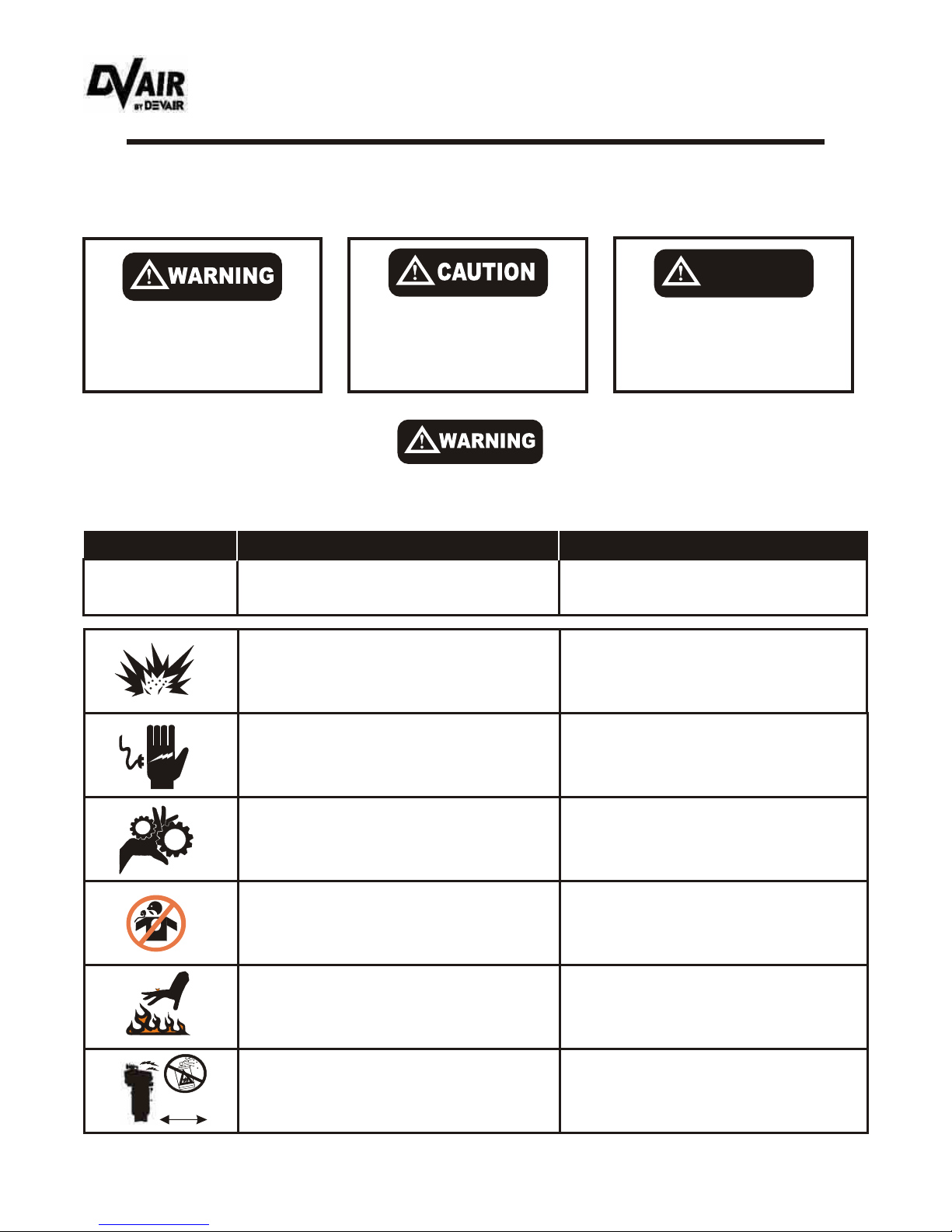
The following hazards may occur during the normal use of the equipment. Please
read the following chart.
In order to operate the Compressor Unit safely and correctly, we have opted to use the following symbols to make you
aware of important points. These points relate to user safety and preventing equipment problems. Please pay close
attention to these sections.
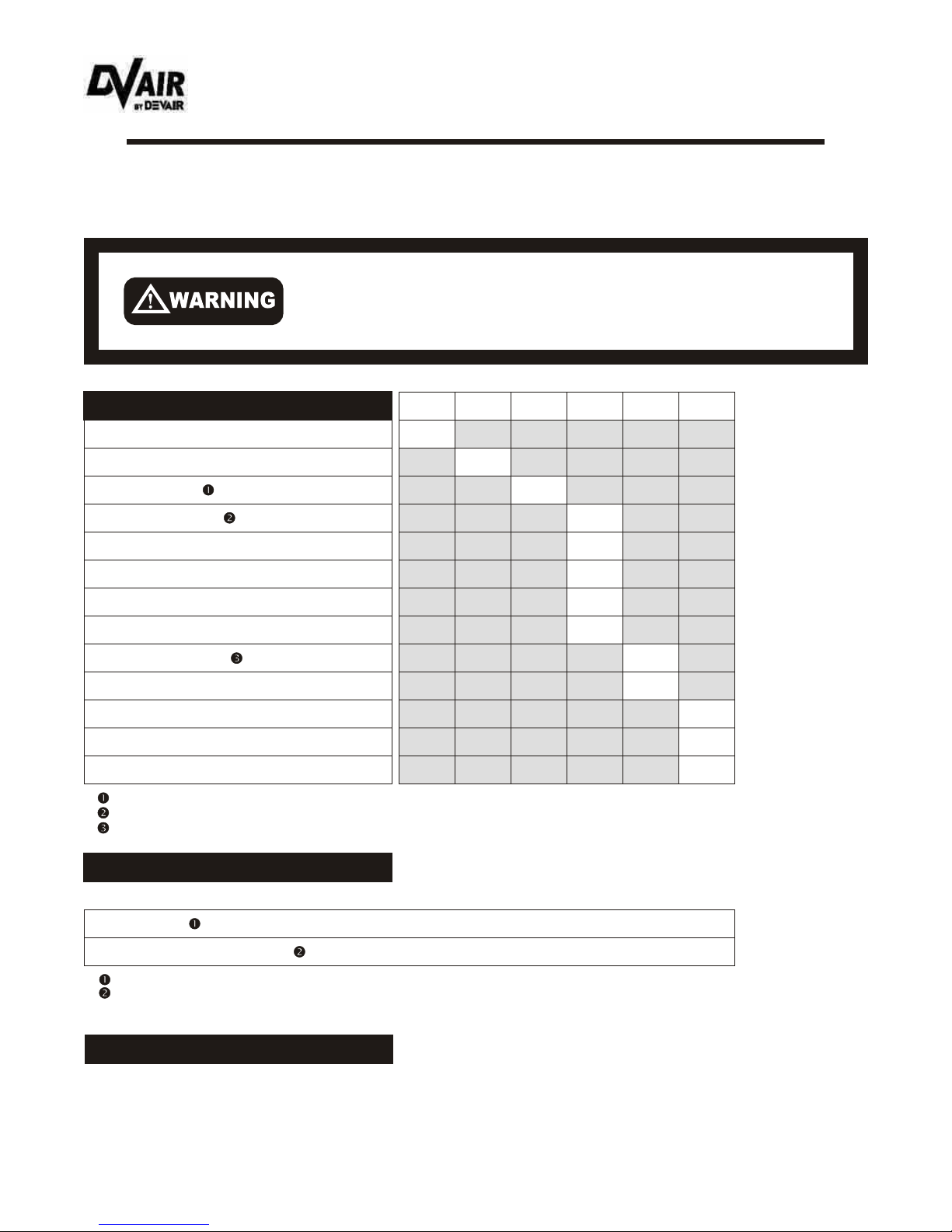
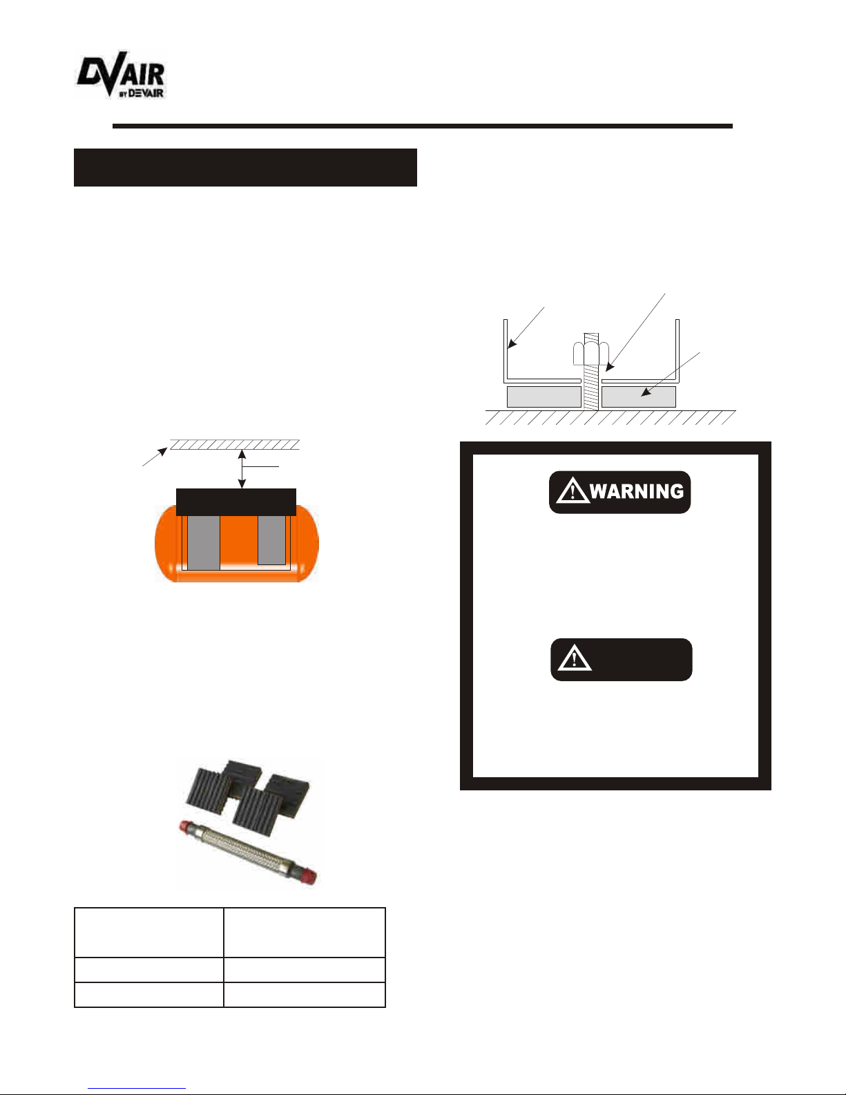
Tampering with the Unit while under full or partial
pressure may cause an explosion.
Relieve all pressure from the Unit before attempting
any repair or maintenance work.
As the Unit starts and stops automatically , serious
injury may result from working on the Compressor with
the power still in the on position.
Shut off all power to the Unit before attempting to
repair or maintain the Compressor.
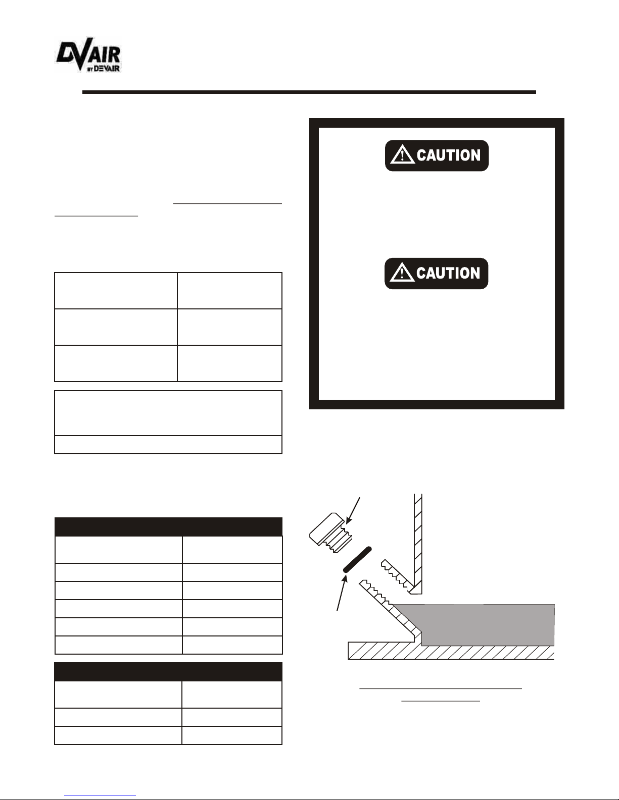
What to look for. How to avoid the hazard
What may occur if precautions are not
observed.
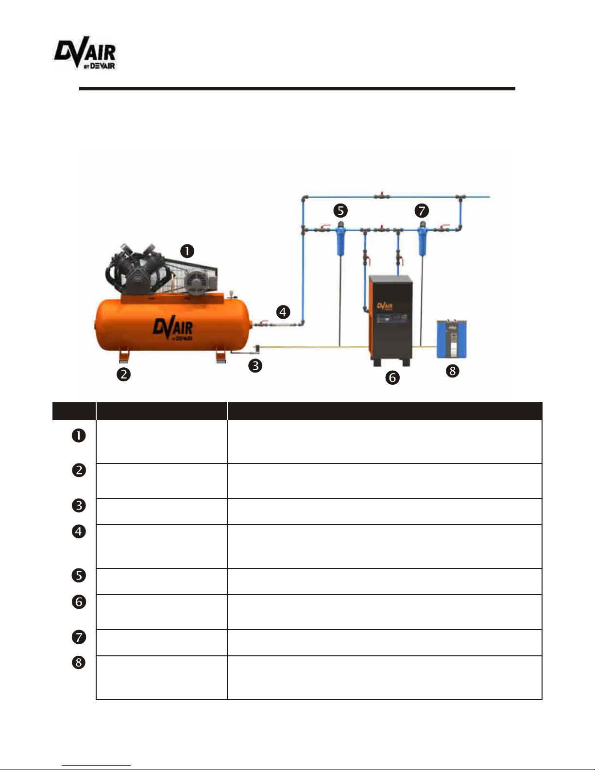
Area: Hazard: Safeguards:
Important safety information. A
hazard that may cause serious
injury or loss of life.
Important information that indicates
how to prevent damage to
equipment, or to avoid a situation
that may cause minor injury.
Information that you should pay
special attention to.
NOTE
- 2 -
Safety Precautions
As the Unit starts and stops automatically, do not come
into contact with moving parts.
Shut off all power to the Unit before attempting to
repair or maintain the Compressor.
Air compressed by the Unit is not suitable for inhaling. It
may contain poisonous vapours harmful to your health.
Never directly inhale compressed air produced by
the Compressor.
Compressor Air End, Motor, and Tubing become hot
when running. Touching these areas may cause
severe burns.
Never touch the Air End, Motor, or Tubing during or
immediately after operation.
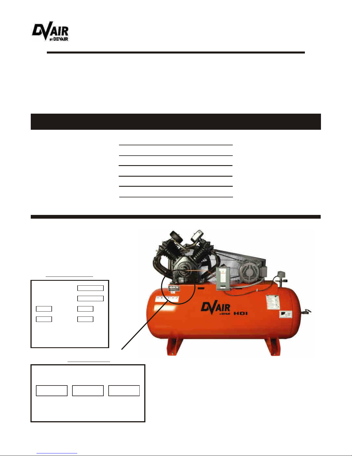
As the electrical compo-nents on the Compressor are
General Purpose and the Motor is Totally Enclosed
(TEFC), there is a potential for explosion, should
vapours be present in the area.
The Compressor must be a minimum of 20 Feet (6.1
Metres) from any source of potentially explosive
vapours.
20FT
6.1m
HDI-01
Mar ‘07
Distributed by: CENTRAIR Air Systems & Supplies, 68 Hooper Rd., Unit 5, Barrie, ON L4N 8Z9
Phone: 705-722-5747 Fax: 705-722-5458 [email protected] www.centrair.ca

Noted below and to follow are the general maintenance guidelines which must be followed and
documented, this in accordance with the Warranty. It is based on the approximate Compressor usage of 40
hours per week. If your particular application varies from this, please adjust accordingly.
Daily Weekly Monthly Every 3
Months
Every 6
Months Yearly
Preventative Maintenance Schedule
HDI-01
Mar ‘07
When servicing the Air Compressor, shut off all power to the Unit,
and drain the Tank of air pressure. Always replace the BeltGuard
after adjusting the Belts or Pulleys.
First Year Maintenance
Second Year Maintenance
Third Year Maintenance
Drain Air Receiver.
Check that Unit unloads when shutting down.
Replace Oil (mineral).
Check lubrication of Motor. Consult literature.
Check Oil level (and top up as required).
Clean and/or blow dust/dirt off Unit.
Check condition/alignment of Belts, Pulley, Flywheel
Inspect Valve Assemblies.
Replace Air Filter.
Replace oil (synthetic).
Check Safety Valves.
Inspect Check Valve.
Inspect Pressure Gauge.
Air Filters are available in the Maintenance Kit. Consult your Pump Bulletin for the appropriate Kit number.
Mineral Oil is available in the Maintenance Kit. Consult your Pump Bulletin for the appropriate Kit number.
Synthetic Oil is available in the Maintenance Kit. Consult your Pump Bulletin for the appropriate Kit number.
X
X
X
X
X
X
X
X
X
X
X
X
X
- 3 -
In the 2nd year of operation, the items as noted in the ‘First Year Maintenance’ must be done as well as the following:
In the 3rd year of operation, complete the items as noted in the ‘First Year Maintenance’.
Replace Valve Discs and Springs. (Replace Valve Assemblies as required.)
Replace Belts.
Belts are available through your local Devair Distributor.
Valve Discs and Springs are available through your local Devair Distributor. Consult your Pump Bulletin for
the appropriate Kit number.
Distributed by: CENTRAIR Air Systems & Supplies, 68 Hooper Rd., Unit 5, Barrie, ON L4N 8Z9
Phone: 705-722-5747 Fax: 705-722-5458 [email protected] www.centrair.ca

Preventative Maintenance Schedule
HDI-01
Mar ‘07
Fourth Year Maintenance
Sixth Year Maintenance
Fifth Year Maintenance
Seventh Year Maintenance
- 4 -
In the 4th year of operation, the items as noted in the ‘First Year Maintenance’ must be done as well as the following:
In the 6th year of operation, the items as noted in the ‘First Year Maintenance’ must be done as well as the following:
In the 5th year of operation, complete the items as noted in the ‘First Year Maintenance’ on Page 3.
In the 7th year of operation, complete the items as noted in the ‘First Year Maintenance’ on Page 3.
Replace Valve Discs and Springs. (Replace Valve Assemblies as required.)
Replace CPR Kit.
Replace Pressure Switch.
Replace Safety Valves on Pump and Tank.
Replace Pressure Gauge.
Replace Belts.
Replace Belts.
Belts are available through your local Devair Distributor.
Valve Discs and Springs are available through your local Devair Distributor. Consult your Pump Bulletin for
the appropriate Kit number.
The ‘CPR’ (Centrifugal Pressure Release) is the Unloader which may be located on the front of the Pump.
The CPR Assembly and Repair Kit part numbers are located in your Pump Bulletin.
Belts are available through your local Devair Distributor.
Valve Discs and Springs are available through your local Devair Distributor. Consult your Pump Bulletin for
the appropriate Kit number.
Insist on Genuine Devair Parts and Kits
when maintaining your Devair Compressor
Pump and Unit.
Distributed by: CENTRAIR Air Systems & Supplies, 68 Hooper Rd., Unit 5, Barrie, ON L4N 8Z9
Phone: 705-722-5747 Fax: 705-722-5458 [email protected] www.centrair.ca

It is the responsibility of the receiver of the goods, either the Distributor or Customer, to ensure that the
product has been shipped in full, and has arrived in suitable condition. Damage to the product may not be
visible at time of off-loading, but may only become apparent upon unpacking or start-up.
Some areas to initially check are as follows:
a) Check for damage to the Belt Guard.
b) If the Belt Guard appears damaged, remove the Guard and turn the Flywheel by
hand to ensure the Crankshaft has not been bent, and that the Belt Drive is properly
aligned and free of distortion.
c) Check the Air Tank and attached Legs for possible damage.
Should there be shortages in shipment or damage to the product:
1) Stop any further unpacking or operation of the product.
2) Make note of the problem on the Freight Bill, should it concern a shortage or visible
damage to the product.
3) Should the damage be noticed only after the product has been received, contact the
transport company immediately to file a claim.
Depending on the problem, it may be wise to photograph the damage. Also, it may
be wise to discuss with the carrier representative the time allotted to give notice of loss
or damage to the product; there may be guidelines which limit time-frames of same.
4) Do not attempt further unpacking or operation of the product. Also, do not discard
any packing material used.
5) A Loss or Damage Claim must be submitted to the carrier and supported by the
following documents:
- Copy of Freight Bill of Lading
- Copy of the Invoice and Estimate to repair, in case of damage
- Damage Report
- Copy of photos, if applicable
Unpacking and Inspection
Each Devair ‘HDI’ Air Compressor is carefully tested and inspected before
shipment. Though every attempt is made to ensure the safe and complete
shipment of our product, freight damage or misplacement of goods may occur.
Shipments of Devair products are the property of the Consignee when the
products leave our facility. Devair Inc. is not responsible for any damages or
shortages caused to the product after it has left our shipping dock.
NOTE
- 5 -
HDI-01
Mar ‘07
Distributed by: CENTRAIR Air Systems & Supplies, 68 Hooper Rd., Unit 5, Barrie, ON L4N 8Z9
Phone: 705-722-5747 Fax: 705-722-5458 [email protected] www.centrair.ca

In the event that you must contact your Devair Distributor or Service Center (to purchase kits, parts, etc.),
you will be asked for the model number and serial number of your Compressor Unit and Pump. As well, you
may be asked for a copy of your Bill of Sale from the vendor from whom you purchased the Unit.
All of this information is required to ensure that you obtain the correct parts and/or service for your Devair
‘HDI’ Compressor Unit.
Electrics of Unit:
Date Purchased:
Pump Nameplate
Unit Nameplate
Serial Number of Pump:
Model Number of Pump:
Serial Number of Unit:
Model Number of Unit: Example: VAV-5062-69
Example: 12345 AB
Example: 230volt/60/3phase
Example: 447
Example: 54321
Unit Identification
12345 AB 175 psi
i) When a flammable liquid is sprayed, there may be danger of fire
or explosion, especially in a closed area.
Ii) Read operating instructions.
Iii) Arcing parts. Keep the Compressor at least 20 feet from explosive vapours.
For Parts and Service, always give Model and Serial Number.
VAV-5062-69
Devair Air Compressors
Model
Caution:
Serial Number Max. Press.
Model No.
500 Min RPM Lubrication
Serial No.
Max RPM @
Max RPM @
PSI
PSI
447
54321
900 175
600 300
Devair
- 6 -
Compressor Identification
HDI-01
Mar ‘07
Distributed by: CENTRAIR Air Systems & Supplies, 68 Hooper Rd., Unit 5, Barrie, ON L4N 8Z9
Phone: 705-722-5747 Fax: 705-722-5458 [email protected] www.centrair.ca

Compressed Air System Design
In designing a compressed air system, there are several factors that must be considered. Though cost may
be a factor in most designs, it cannot be the final determining factor, especially where air quality, air volume,
and air pressure are critical.
Shown below is a typical layout of a compressed air system.
Air Compressor: is the heart of the compressed air system. Ensure it is sized for the
application, is installed in a safe and correct manner, and is
maintained according to the manufacturers guidelines.
Flex Hose: protects the building air lines from any undue vibration caused by
the Compressor, and allows for any mis-alignment between the
Unit outlet and the building piping.
Refrigerated Air Dryer: removes the moisture from the compressed air by lowering its
temperature.
Oil-Water Separator: separates the oil from the moisture drained by the Refrigerated Air
Dryer and Filters. The oil is trapped by internal Filters, while the
water is allowed to be dispensed to the building drain.
Separator Filter: acts as a pre-filter to the Refrigerated Air Dryer.
Coalescing Filter: removes oil from the compressed air
Vibration Isolators: absorb any vibration caused by the Compressor, allow for any
irregularities in the floor, and make the Unit marginally quieter.
Automatic Drain: drains the Compressor Tank on a regular basis.
Component: Description:
- 7 -
HDI-01
Mar ‘07
Distributed by: CENTRAIR Air Systems & Supplies, 68 Hooper Rd., Unit 5, Barrie, ON L4N 8Z9
Phone: 705-722-5747 Fax: 705-722-5458 [email protected] www.centrair.ca

Please refer to the drawing below, as it identifies the major components of a typical Air Compressor Unit
and their function. (Some Units may vary slightly from this design, eg. gas powered or base-mounted
Compressors.
Please refer to the Compressor Pump Service Bulletin provided with your Unit to identify the
part numbers, location, and quantities for your particular Compressor Pump model.
Check Valve
One way Valve that allows air
to enter the Tank, but prevents
the air from flowing back into
the Compressor Pump
Compressor Pump
Compresses the air
Aftercooler Tube
This Tube leads the compressed
air to the Air Receiver while
allowing the air to cool
Intercooler Tube
This Tube cools the compressed air while
leading it from the low pressure Cylinder to
the high pressure Cylinder
Electric Motor
Belt Guard
Ball Valve
Discharge/outlet
Drain Valve
Allows the operator to drain
the moisture from the Tank
Air Receiver (Tank)
Pressure Switch
A pneumatically operated electric
Switch for starting and stopping the
Unit at predetermined minimum
and maximum pressures
Pressure Gauge
Gauge reflects current Tank
pressure
Magnetic Starter
An electrically operated device which
receives a signal from the Pressure
Switch and allows power to flow to the
Motor.
Compressor Terminology
- 8 -
Pump Components
HDI-01
Mar ‘07
Distributed by: CENTRAIR Air Systems & Supplies, 68 Hooper Rd., Unit 5, Barrie, ON L4N 8Z9
Phone: 705-722-5747 Fax: 705-722-5458 [email protected] www.centrair.ca

The Compressor Unit must be located in a dry,
clean, cool, and well ventilated area. If possible,
the Compressor should be located in a
separate room or area, away from the general
operations of the shop.
Allow room for easy access to the Unit for
maintenance purposes, as well as to ensure a
maximum cooling effect caused by the
Flywheel. To ensure that the Unit is cooling
properly, allow a minimum of 18” (0.5 m)
between the Beltguard and any adjacent wall,
etc. as shown below.
Ensure that the floor under the Unit is smooth
and level. The Compressor must sit squarely on
all four Feet.
Devair has available Installation Kits which
include a) (4) Isolator Pads for use under each
Foot, and b) stainless steel Flex Hose for
installation between the Unit Tank and the shop
piping.,
If anchoring a Unit to the floor, ensure that there
is roughly a 1/4” (0.75 cm) gap between the nut
and the Compressor Foot. Do not bolt down
tightly.
A Compressor Unit releases a great deal of heat
that, when not taken from the Unit area, could
cause severe problems. It is very important that
the Unit be located in a relatively large area or,
when in an enclosed area, cool air is introduced
and the heat is taken out, this by means of
intake and exhaust fans.
The amount of heat generated by an Air
Compressor is calculated by simply multiplying
the Unit Horsepower by 2500.
Example: 15 HP Unit x 2500 = 37500 BTU/hour
The Compressor must not be
operated in a confined area where
the heat from the Unit cannot readily
escape.
NOTE
Never clamp or bolt air receiver Feet
tightly to the floor or support
structure. Doing so may greatly
increase stress on the Tank, causing
it to weaken and/or fracture.
Installation - Mechanical
Location of the Unit.
18” (0.5 m)
minimum
Building
Wall, etc.
Floor
Isolator
Pad
Compressor
Foot
1/4” (0.75 cm)
Gap
Compressor
BeltGuard
Devair Installation
Kit Number
IK515
IK2530
5 To 15 HP
25 and 30 HP
‘HDI’ Compressor
Horsepower
- 9 -
HDI-01
Mar ‘07
Distributed by: CENTRAIR Air Systems & Supplies, 68 Hooper Rd., Unit 5, Barrie, ON L4N 8Z9
Phone: 705-722-5747 Fax: 705-722-5458 [email protected] www.centrair.ca

Fill the Crankcase to the lowest thread at the Oil
Fill Port Opening. Do not under or overfill.
See drawing below.
Always replace the O-Ring when filling, and
tightly screw in Oil Fill Plug using a crescent
w r e n c h . U s e o n l y D e v a i r P r e m i u m
Compressor Oil for the Air Compressor, as it
has been specially formulated for your Unit, and
contains only two additives, a rust inhibitor and
an anti foaming agent.
The following Maintenance Kits are available
through your Devair Distributor, the Kits
including Devair Premium Oil and Air Filter (s).
Do not attempt to operate the Unit without
first checking whether there is Oil in the
Pump. Add Oil as required. Serious
damage may result from use, however
limited, without Oil.
Use of improper Oil may negatively a f fect
Compressor Pump performance or
shorten Pump life. Resulting problems are
not covered by the Devair Inc. Air
Compressor Warranty.
Pump Lubrication
- 10 -
Devair Premium
Mineral Oils
Devair Pump Model
Devair Pump Model
Devair Premium Synthetic Oil (used in
high heat or high duty applications or
when Beltguard Aftercoolers are used)
DV Lube20 (20 Wgt)
Part No. ‘PR20’
DV Lube30 (30 Wgt)
Part No. ‘PR30’
123
247
44642
OJ-2000 (20 Weight)
223
447
247
447
Up to 90°F (32°C)
MK-223
MKS-247
MK-247
90°F + (32°C +)
MK-223
MKS-447
MK-247
MK-447
Room (Ambient)
Temperature
Kit Part Number
Kit Part Number
'O' Ring
Proper Oil Level
(to bottom thread of Oil Port)
Oil Filler
Plug
Section Through CrankCase
at Oil Fill Port
Kits c/w Mineral Oil (20 Weight only)
Kits c/w Synthetic Oil
HDI-01
Mar ‘07
Distributed by: CENTRAIR Air Systems & Supplies, 68 Hooper Rd., Unit 5, Barrie, ON L4N 8Z9
Phone: 705-722-5747 Fax: 705-722-5458 [email protected] www.centrair.ca

It is your responsibility to ensure that the
Compressor Unit is electrically connected in a
safe and correct manner. Any electrical work
must be carried out by a competent Electrician,
and be done is such a way that it meets all
applicable Codes and Regulations.
A Magnetic Starter, as shown below, must be an
integral part of the Compressor Unit circuit as it
provides overload protection to the Electric
Motor. A Magnetic Starter can be purchased
separate from the Unit, or factory-mounted at
time of manufacture.
Typical Electrical Installation
of a Compressor Unit
Typical Magnetic Starter Wiring
(Subject to Local Codes & Authorities)
Please note that, under normal
conditions, the Compressor Unit will
operate intermittently .
The Unit starts/stops without warning.
Should it be necessary to service the
Unit, ensure the power source has been
shut down and locked off. This must be
done to prevent personal injury, or
damage to the unit.
Do not attempt to operate the Air
Compressor Unit without first checking
the Oil level in the Pump. Add Oil as
required. Serious damage may result
from use without Oil.
Failure to connect the Compressor
correctly to your building's electrical
services may result in serious
personal injury, or damage to
equipment.
Pressure
Switch
Motor
C
L
L L 3
2
1
Installation - Electrical
Main Fuse Box
Magnetic Starter
Fused Disconnect
or Circuit Breaker
- 11 -
HDI-01
Mar ‘07
Distributed by: CENTRAIR Air Systems & Supplies, 68 Hooper Rd., Unit 5, Barrie, ON L4N 8Z9
Phone: 705-722-5747 Fax: 705-722-5458 [email protected] www.centrair.ca

Wiring must be done in a manner that the full
Motor nameplate voltage +/- 10% is available at
the Motor terminals during startup.
The Warranty that exists on the Electric Motor is
that of the original manufacturer. In the event of
a Motor failure, contact your Devair Distributor or
Service Centre for the location of the nearest
authorized Motor Service Centre.
To ensure that your new Devair Compressor will
work when required, you must ensure that it is
correctly wired to your building service. It is the
responsibility of the licenced Electrician to ensure
that:
A) the Unit that you have purchased is suitable for
your particular buildings electrical service.
B) protective devices such as a Magnetic Starter,
Fused Disconnect, etc. have been sized and
installed correctly.
C) any electrical accessories purchased with your
Compressor have been wired correctly
D) the wiring of the Unit meets with all applicable
codes and regulations.
E) when completed, the Unit works in both a safe
and correct manner.
Failure of the Compressor due to an incorrect
electrical installation is not covered by the
manufacturers warranty.
Use of an incorrect Electric Motor for
your particular building service will
result in premature Motor failure, and
is not covered by the Devair or Motor
manufacturer's Warranty.
NOTE
Installation - Electrical (cont’d)
Motors
Pump Rotation
Why hire a licensed Electrician?
The Compressor is to be wired in a manner that
the rotation of the Flywheel causes the air to be
blown from the Flywheel forward over the Pump.
This, coupled with the free area of a minimum of
18” (0.5 m) behind the Beltguard, allows the
Pump to cool properly.
When facing the nameplate
side of the Unit, the
Flywheel rotation must be
clockwise.
- 12 -
HDI-01
Mar ‘07
Distributed by: CENTRAIR Air Systems & Supplies, 68 Hooper Rd., Unit 5, Barrie, ON L4N 8Z9
Phone: 705-722-5747 Fax: 705-722-5458 [email protected] www.centrair.ca

Accessories - Pneumatic Autodrain
Maximum working pressure of 200 psi (13.8 Bar).
Minimum working pressure of 30 psi (2.1 Bar).
Anodized aluminum body.
Stainless steel piston, spring, ball, screens, and
reservoir.
Buna seals and teflon ring. AutoDrain Assembly Drain
Port
Reservoir
Moisture
from Tank
Pilot Signal
from
Unloader
1. Maintenance/service work must only be done when
the Autodrain is not under pressure.
2. Ensure the Autodrain is not subjected to
temperatures below freezing.
3. Suitable arrangements must be made to ensure the
moisture is properly contained once evacuated from
the AutoDrain.
The ‘AD-9400’ Autodrain is designed to drain moisture from the Compressor Unit each time the Unit
reaches maximum pressure and shuts off. As shown, the Unit receives its ‘pilot’ signal from the
Compressor Unloader, being tied into the Unloader Line by means of a Compression Tee.
All that is required for the automatic operation of the Autodrain is an intermittent air source like that
obtained by tapping into the Compressor Unloader Line.
A) The pilot signal (or air pressure) on the Unloader Line forces an internal Piston past the Drain Port,
sealing the internal Chamber from atmosphere.
B) As the Piston is forced forward, the internal Stainless Steel Ball Valve is opened, permitting
condensate and oil to be forced up into the Reservoir.
C) The air in the top of the Reservoir is compressed to system pressure.
D) As the pilot signal is returned to zero, the internal Piston returns, closing the system from the
atmosphere.
E) When the Piston reaches it’s original position, the Drain Port is opened, allowing the condensate to
escape.
As noted, suitable arrangements must be made to contain the condensate that is expelled from the
Autodrain. As the condensate may contain traces of oil, it must be disposed of accordingly.
What is the purpose of the ‘AD-9400’ Autodrain?
Specifications:
Important Information: Maintenance:
The Trap Mesh and Flat Mesh in the AutoDrain must be
cleaned periodically in order to ensure the Unit works
properly, and does so for a long period of time.
Devair offers a Repair Kit for the Unit, namely an ‘RK-AD-
9400’. The Kit includes a Flat Screen, Trap Screen, ‘O’
Ring, Piston and Seal Assembly, and an End Cap
Gasket.
- 13 -
HDI-01
Mar ‘07
Distributed by: CENTRAIR Air Systems & Supplies, 68 Hooper Rd., Unit 5, Barrie, ON L4N 8Z9
Phone: 705-722-5747 Fax: 705-722-5458 [email protected] www.centrair.ca

Accessories - Electronic Autodrain
Maximum working pressure of 230 psi (16 Bar).
Includes Manual Ball Valve and Filter
Drain duration of between .05 to 10 seconds
Operating cycle time of 1 to 45 minutes
UL and CSA approved
Wire Mesh
Filter
Moisture
from Tank
1. Maintenance/service work must only be done when
the Autodrain is not under pressure.
2. Ensure the Autodrain is not subjected to
temperatures below freezing.
3. Suitable arrangements must be made to ensure the
moisture is properly contained once evacuated from
the AutoDrain.
The ‘KK-9840’ Autodrain is designed to drain moisture from the Compressor Unit based on an internal
Timer. The Timer is an electrical device, requires 120-60-1 to operate, and can therefore be plugged
into any wall outlet. A six foot (1.8 m) power cord is supplied.
The Autodrain is equipped with a Ball Valve, this allowing the air/moisture supply to the Drain to be
closed. The Ball Valve is also coupled with an internal wire mesh Filter, this to clean any impurities from
the air/moisture and prevent them from clogging the Autodrain mechanism.
By simply adjusting the two dials on the Autodrain Timer, the duration of the drains and the time
between drains can be altered to suit your particular application. The duration for the drain can be set
between 0.5 to 10 seconds, the time between drains 1 to 45 minutes.
As noted, suitable arrangements must be made to contain the condensate that is expelled from the
Autodrain. As the condensate may contain traces of oil, it must be disposed of accordingly.
What is the purpose of the ‘KK-9840’ Autodrain?
Specifications:
Important Information: Maintenance:
The Wire Mesh Filter as shown above must be cleaned
periodically in order to ensure that the Unit works
properly, and does so for a long period of time.
De-pressurize the Unit, remove the End Cap, and remove
the Wire Mesh Filter. Clean with water, and replace.
Ball Valve
End Cap
Timer
- 14 -
HDI-01
Mar ‘07
Distributed by: CENTRAIR Air Systems & Supplies, 68 Hooper Rd., Unit 5, Barrie, ON L4N 8Z9
Phone: 705-722-5747 Fax: 705-722-5458 [email protected] www.centrair.ca

Accessories - Oil Monitor
- 15 -
Die cast aluminum case painted black.
Internal brass float registers oil level.
Lens allows viewing of oil level.
Suitable for use with voltages up to 230v ac.
Maximum working pressure of 25 psi (1.72 Bar).
1. The Oil Monitor, if not electrically wired by the
manufacturer, must be connected by a licensed
Electrician. Please wire as per the following page.
2. Test the Oil Monitor on a regular basis to ensure it is
operating correctly.
The ‘OM-9400’ Oil Monitor provides a means of ensuring there is sufficient oil in the Pump during
regular Compressor operation. It contains a Micro-switch which registers the level of oil in the Pump.
Should the level of oil drop below a preset limit, the Micro-switch will open, causing the Unit to shut
down.
The Oil Monitor is an electrical device, requiring 120 or 230 volts to operate. On Units where the
voltage is 460 or 575, a Step-down Transformer or alternate power source must be provided by a
licensed Electrician. The Electrician must then ensure that the wiring of the Monitor(s) meets all
applicable codes and regulations.
To ensure the Oil Monitor is functioning as designed, it is best to a) test the Monitor on a regular basis
and b) check the oil level manually on a regular basis. To test the Monitor, simply turn the Knob on the
Monitor Face in a counter-clockwise direction, thereby leading the Switch to believe the oil level is
below the preset limit.
Please be advised that, in some instances, the Level Indicator may read as ‘Low’ on the Monitor. This is
acceptable. Please test the Monitor to ensure it is functioning correctly in this case.
What is the purpose of the ‘OM-9400’ Oil Monitor?
Specifications:
Important Information: Maintenance:
Test the Oil Monitor on a regular basis to ensure it is
working as designed.
As well, check for any oil or air leaks on the Monitor and
on the oil tubing and air piping leading to the Pump.
Level Indicator
Electrical
Access Panel
Test Knob
HDI-01
Mar ‘07
Distributed by: CENTRAIR Air Systems & Supplies, 68 Hooper Rd., Unit 5, Barrie, ON L4N 8Z9
Phone: 705-722-5747 Fax: 705-722-5458 [email protected] www.centrair.ca

Accessories - Oil Monitor (Cont’d)
- 16 -
HDI-01
Mar ‘07
Distributed by: CENTRAIR Air Systems & Supplies, 68 Hooper Rd., Unit 5, Barrie, ON L4N 8Z9
Phone: 705-722-5747 Fax: 705-722-5458 [email protected] www.centrair.ca

Accessories - Beltguard Aftercoolers
Maximum working pressure of 175 psi (12.08 Bar).
Reduces the temperature of the compressed air by
approximately 100°F to 125°F between the input
and output of the Cooler
Piping to
Tank
Piping from
Pump
1. There must be a minimum of 18” (0.5 m)
between the Aftercooler and any obstruction.
2. Devair ‘OJ2000’ Oil must be used in the
Compressor Pump.
3. The Beltguard Aftercooler must be cleaned on
a regular basis with compressed air to ensure
the unobstructed air flow through the cooler.
A Beltguard Aftercooler is designed to decrease the temperature of the compressed air as it exits the
Compressor Pump and before it enters the Air Receiver Tank. The compressed air is cooled as it
passes through the ‘radiator style’ Aftercooler, the air flow created by the draw of the Pump Flywheel as
it turns.
When using a Beltguard Aftercooler, it is imperative that:
A) the Beltguard be at least the required minimum distance of 18” (0.5 m) from any obstruction or
wall. With this design, maximum air flow through the Aftercooler is critical to both ensure the
cooler works effectively and the Pump receives proper cooling.
B) the Oil used in the Pump be a synthetic oil, namely ‘Oj2000’.
If the above criteria are not met, the Aftercooler will not work effectively, and the Pump could fail
prematurely.
What is the purpose of a Beltguard Aftercooler?
Specifications:
Important Information: Maintenance:
The Beltguard Aftercooler must be cleaned with
compressed air on a regular basis in order that
any dust, residue, etc is removed and does not
impede the air flow through the cooler. Failure to
do this will result in premature Compressor
failure.
Beltguard
Aftercooler
- 17 -
HDI-01
Mar ‘07
Distributed by: CENTRAIR Air Systems & Supplies, 68 Hooper Rd., Unit 5, Barrie, ON L4N 8Z9
Phone: 705-722-5747 Fax: 705-722-5458 [email protected] www.centrair.ca

Accessories - Duplex Alternator Relays
What is the purpose of an Alternator Relay ?
An Alternator Relay is used with a Duplex Compressor Unit, namely a Unit with two Pumps and two
Motors on one large Tank. Coupled with two Magnetic Starters, the Alternator Relay allows the Pumps
to alternate back and forth. This is necessary to spread the compressed air load over the two Pumps.
Naming the Pump and Motor assemblies on the Tank as being Unit #1 and Unit #2 allows the
alternating to take place. The ‘Lead Pressure Switch’ (or ‘PS1’) regulates the Units to start, and is
therefore set at the maximum pressure setting. (In smaller Compressors, this is generally the Switch
with the Unloader.) The ‘Lag Pressure Switch’ (or ‘PS2’) is set at 10 psi less than the Lead Switch, and
will bring the second Unit on only if the pressure in the Tank goes below that of the ‘cut-in’ pressure of
‘PS2’. (For example, this will occur when the Unit is started at 0 psi in the Tank.)
Shown below is a typical schematic for a Duplex Unit c/w (2) Magnetic Starters and Alternator Relay.
- 18 -
HDI-01
Mar ‘07
Distributed by: CENTRAIR Air Systems & Supplies, 68 Hooper Rd., Unit 5, Barrie, ON L4N 8Z9
Phone: 705-722-5747 Fax: 705-722-5458 [email protected] www.centrair.ca

1) Remove the Oil Filler Plug, and ensure
that there is Oil in the Crankcase. Refer to
the "Lubrication" section (page 8) in this
manual for proper type and level of Oil.
2) Replace the Oil Filler Plug, and use a
crescent wrench to tighten snug plus 1/4
turn.
3) Do a visual inspection of the Unit, and
ensure that all Bolt heads are sufficiently
tightened. This must be done, as some
fasteners may become loose in transit.
4) Turn the Compressor 'On' momentarily by
positioning the Fused Disconnect in the 'On'
position. Ensure that the Flywheel is turning
in the correct direction. See "Pump
Rotation" (page 10).
6) After having run the Compressor Unit for 30
minutes, close the Ball Valve, and allow the
unit to reach maximum operating pressure.
Ensure that the Compressor shuts down at
the pre-set maximum pressure, and the
head pressure is released through either
the front of the Pump (the CPR) or at the
Pressure Switch.
7) Check the Compressor and Piping Systems
for air leaks, and correct as required.
8) Stop the Compressor, and check the Oil
level in the Crankcase. Add Oil as required.
5) Open the Compressor's Ball Valve, and
start the Unit. Ensure that the air is
escaping to atmosphere. Allow the Unit to
operate in this fashion for approximately 30
minutes. This lubricates the Pistons,
Bearings, and all internal surfaces.
Initial Start-Up
Do not place any materials on or against
the Belt Guard, or the Compressor Unit as
a whole. Placing materials there will limit
the cooling of the Compressor, and could
lead to premature failure.
Shut off all power to the Air Compressor
Unit before attempting any repair or
maintenance.
On Compressors with 3 phase power,
adjust the wiring at the Motor terminals if
the rotation is incorrect. Refer to the
wiring diagram at the Motor terminal
box.
NOTE
During the first few days of operation, check the Unit periodically to ensure it is
running smoothly and the controls are operating properly. Should you notice
any areas of concern, contact your Devair Distributor or Authorized Service
Centre.
NOTE
Do not attempt to operate the Unit without first checking whether there
is Oil in the Pump. Add Oil as required. Serious damage may result
from use, however limited, without Oil.
NOTE
Initial Start-up Procedure
- 19 -
HDI-01
Mar ‘07
Distributed by: CENTRAIR Air Systems & Supplies, 68 Hooper Rd., Unit 5, Barrie, ON L4N 8Z9
Phone: 705-722-5747 Fax: 705-722-5458 [email protected] www.centrair.ca

A. Excessive Noise
B. Oil Pumping and
Excessive Carbon
Formation
or
Appearance of Water
and Oil in the in the Air
Lines.
1. Install a moisture separator and/or oil
filter in the air line at least 8 feet
from the air receiver.
2. Check for air leaks. If no leaks are
found, you may require an additional
compressor unit, as your air demand
is too much for the existing unit.
3. Clean or replace the piping. Contact
Devair or contact your local
Distributor or Service Centre for sizing
requirements.
4. Replace air intake filter.
5. Fill to proper level.
6. Check 'Lubrication' in this manual or
contact your local Devair Distributor or
Service Centre.
7. Clean or replace as required.
8. Replace valve assemblies.
9. Replace rings and check cylinder
walls for scoring.
1. High ambient temperature and/or
humidity.
2. High percentage of running time. (80%
to 100%)
3. Obstructed or undersized air intake
piping, where remote air Intake is
used.
4. Restricted air intake filter.
5. Overfilling the crankcase with oil.
6. Wrong type of oil.
7. Carbonned exhaust valves.
8. Worn valves.
9. Worn piston rings.
1. Loose flywheel or motor pulley.
2. Loose valve.
3. If noisy only during start-up, check for
loose belts.
4. Vibrating beltguard, piping, or loose belts.
5. Unit not installed level.
6. Improper grade or level of oil in crankcase.
7. Carbon or other foreign material on head
of piston.
8. Normal sound amplified through floor or
carried through remote air intake (when
used).
9. If the noise is a knock, and cannot be
attributed to any of the above, the
problem could be worn bearings.
1. Tighten as required.
2. Inspect valve for damage. Replace as
required. Check to ensure valve is
seated properly in head. Reinstall,
tightening valve plug and set screw
3. Tighten until no slippage is apparent.
Allow some slack.
4. Tighten as required.
5. Ensure that unit is mounted level.
6. Use correct oil and ensure level is
correct.
7. Clean top of piston. Check cylinder
walls for scoring, etc.
8. Mount unit on vibration isolators.
Insulate intake piping from building.
9. Worn main bearings can usually be
detected by noticeable end play on the
flywheel. Replace the main bearings.
Worn connecting rod insert bearings
or connecting rods may be detected by
removing a valve and watching the
piston while moving the flywheel by
hand. If the flywheel can be moved at
midstroke without movement of the
piston, bearing inserts or connecting
rod may need to be replaced.
Suggested Correction Condition
Cause
When servicing the Compressor, shut off all power to the Unit, and
drain the Tank of air pressure. Always replace the BeltGuard after
adjusting the Belts or Pulleys.
Trouble-Shooting Guide
- 20 -
HDI-01
Mar ‘07
Distributed by: CENTRAIR Air Systems & Supplies, 68 Hooper Rd., Unit 5, Barrie, ON L4N 8Z9
Phone: 705-722-5747 Fax: 705-722-5458 [email protected] www.centrair.ca
Other manuals for HDI-01
1
Other Devair Air Compressor manuals
Popular Air Compressor manuals by other brands

Air
Air Black Ridge BR180D manual

EINHELL
EINHELL Euro 8/24 operating instructions

Dometic
Dometic CoolAir SP950C installation manual

AllTrade
AllTrade Air-Plus 540010 instruction manual

Zgonc
Zgonc Yellow Profi Line YPL 500 Translation from the original instruction manual

Gardner Denver
Gardner Denver EAQ99S Operating and service manual