Chandler Limited RS660 User manual

For more information, visit www.chandlerlimited.com. © 2022 Chandler Limited, Inc. All Rights Reserved. UM RS660-101022
Abbey Road Studios, EMI, RS and their associated logos are trademarks of EMI (IP) Limited.
4
3
2
I
0
6
7
8
9
5
I0
®
-4
-3
-2
-I
0
-6
-7
-8
-9
-5
-I0
E
M I L
T
D
...
E
R
S
P
M
O
R
S
O
C
TIME CONSTANT
OUTPUTINPUT
POWER
TYPE RS660
4
3
2
I
6
7
5
THD
COMP
LIMIT
LINK
dB
COMPRESSION
3
0
0
2
0
1
5
1
0
5
CHANDLER LIMITED®
RS660 COMPRESSOR
USER MANUAL
OFFICIAL
EQUIPMENT
UM RS660-101022

2RS660-101022
RS660 COMPRESSOR
INTRODUCTION ------------------------------------------------- 3
RS660 Compressor ---------------------------------------------- 3
History ------------------------------------------------------ 3
SHIPMENT AND STORAGE ----------------------------------------- 4
Packaging ----------------------------------------------------- 4
INSTALLATION -------------------------------------------------- 5
Rack Mounting ------------------------------------------------- 5
Power ------------------------------------------------------- 5
Audio Interconnections ------------------------------------------- 6
Link -------------------------------------------------------- 6
Output Impedance----------------------------------------------- 7
CONTROLS AND INSTRUMENTS ------------------------------------ 7
BAL. -------------------------------------------------------- 7
Input -------------------------------------------------------- 8
Output ------------------------------------------------------ 9
Link -------------------------------------------------------- 9
Compressor Modes ---------------------------------------------- 9
Time Constant ------------------------------------------------- 10
Metering ----------------------------------------------------- 10
MAINTENANCE INSTRUCTIONS ------------------------------------ 11
Valves ------------------------------------------------------- 11
Pilot Lamp ---------------------------------------------------- 11
Circuit Protection ----------------------------------------------- 12
TECHNICAL SPECIFICAITONS -------------------------------------- 12
SERVICE -------------------------------------------------------- 13
United States -------------------------------------------------- 13
International -------------------------------------------------- 13
CE CERTIFICATION----------------------------------------------- 13

3RS660-101022
INTRODUCTION
RS660 Compressor
Thank you for purchasing the Chandler Limited RS660 Com-
pressor, you now own a piece of EMI/Abbey Road Studios
ocial equipment.
Rather than a reproduction of existing equipment, the RS660
Compressor stands apart and represents a path forward in
the recording engineering development department. Capa-
ble of taming an array of dynamic sources, the new RS660
Compressor and limiter is at home alongside the historic
units from which it was hewn and adds to the modern engi-
neer’s cache of analog signal processors.
Where form follows function, the feature set is straight for-
ward, easily identiable and neatly arranged. However, upon
initial listen, the tone and character of the RS660 is remark-
able; the engineer will nd it eortless to quickly realize a
sound and desired result.
Your Chandler Limited RS660 Compressor has been care-
fully crafted and built by hand at Chandler Limited’s factory
in Shell Rock IA, U.S.A., using through-hole components for,
the ultimate analog experience.
At Chandler Limited we are proud of our American made
products and we hope you like them!
Please feel free to call our shop anytime for help or ques-
tions.
Phone: (319) 885-4200.
History
The Fairchild 660 mono valve (vacuum tube) compressor ar-
rived at EMI’s Abbey Road Studios in 1964.
The Fairchild 660 found favor with Abbey Road’s engineers
for vocals and drums and became a staple for The Beatles’
records.
The Fairchild 660 — which has a dierent vibe than the ste-
reo 670 — is highly desired for its unique tonal quality and
reactivity.
The sound of the Fairchild 660 gave vocals a presence to the
sound and its eect on Ringo’s drums made cymbals sound
backwards. It was used for a sound and it made a statement.
First designed in 1960 by Abbey Road Technical sta, the EMI
RS124 compressor is one of the most coveted pieces of re-
cording gear ever developed.
During the late 1950’s, EMI acquired Altec 436B compres-
sors, and soon realized the units were insucient for criti-
cal recording applications. Livey, Page and Batchelor worked
to modify the Altecs to meet their standards and ultimately
ended up designing an entirely new compressor in the pro-
cess, the EMI RS124.
The RS124 was popular with Abbey Road Studios’ engineers.
The RS124 added its unique character to single instruments,
rhythm busses and entire mixes. So integral to the recording,
mixing, and mastering process, a pair can be seen in almost
every control room photo in Abbey Road during the 60s pe-
riod.
OFFICIAL
EQUIPMENT

4RS660-101022
SHIPMENT AND STORAGE
Packaging
This packaging has been designed specically for Chandler Limited equipment. The cardboard carton and rigid foam sur-
rounds provide protection for shipment and storage. Please retain the container and associated materials for future use.
*Note: PSU rigid foam surrounds and sheets are not included for equipment shipped without a power supply unit inside the
equipment container.
CARDBOARD
CARTON
FACEPLATE
CUTOUT
EQUIPMENT
RIGID FOAM
SURROUND

5RS660-101022
OUTPUT INPUT
AINS VOLTAGE
110-120V
220-240V
LINK
TIP- CV
SLEEVE- 0v
E
IL
T
D
...
E
R
S
P
O
R
S
O
C
R
T
0
Y
P
E
S
6
6
FUSE .25 AP
SLO BLO
OUTPUT IPEDANCE
200
600
FUSE
Chandler Limited
RS660
000001
INSTALLATION
Rack Mounting
The RS660 Compressor contained in a two space, 19 inch
rack-mountable chassis.
Heat in any studio environment is the enemy. For longevity
and reliable service, install and maintain in a well-ventilated
rack.
Power
The Chandler Limited RS660 Compressor features an inter-
nal power supply. Connection is made at the IEC receptacle
using the supplied IEC power cable. Power is preset internally
to operate at either 120V or 220V.
Protection of the circuit has been accounted for by way of a
.25 Amp (250mA) 250V SLO-BLO fuse, which is accessible by
means of a bayonet style fuse assembly.
E
M
IL
T
D
.
..
E
R
S
P
M
O
R
S
O
C
TIME CONSTANT
POWER
TYPE RS660
4
3
I
6
7
5
OUTPUT
MAINS VOLTAGE
110-120V
220-240V
E
M I L
T
D
...
E
R
S
P
M
O
R
S
O
C
R
T
0
Y
P
E
S
6
6
FUSE .25 AMP
SLO BLO
FUSE
Cycling power to the RS660 is achieved by switching the
ON/OFF power switch (located far right of the front panel)
for the desired condition. When the RS660 is powered on,
the pilot lamp — located on the front — panel will illuminate.
Note: All interconnections should be made prior to power-
ing on the unit.
Note: A ten-minute warm-up period should be observed
prior to passing signal through the unit.

6RS660-101022
Link
Provision has been made for stereo linking of two RS660
Compressors, by means of the female ¼” LINK connector
located on the rear of the unit, and using a standard ¼” ca-
ble. For further notes on operation under linked conditions,
review the “Link” section within the “Controls and Instru-
ments” chapter of this manual.
Note: Link cable purchased separately.
Audio Interconnections
On the rear panel of the RS660 Compressor exists two XLR
jacks (wired pin 2 hot), one for INPUT, and the other for
OUTPUT. Both input and output connections are +4, trans-
former balanced.
Note: Input impedance is 15k ohms.
LINK -USE STANDARD 1/4” TIP - SLEEVE CABLE CV
0v
OUTPUT
LINK
TIP- CV
SLEEVE- 0v
OUTPUT IMPEDANCE
200
600
INPUT
OUTPUT IMPEDANCE
200
600
Chandler Limited
RS660
000001
OUTPUT
MAINS VOLTAGE
110-120V
220-240V
LINK
TIP- CV
SLEEVE- 0v
E
M I L
T
D
...
E
R
S
P
M
O
R
S
O
C
R
T
0
Y
P
E
S
6
6

7RS660-101022
Output Impedance
OUTPUT IMPEDANCE is 600/200 ohms switchable. The 600
ohms setting may be more amenable to the modern studio
environment. The 200 ohms impedance setting was Abbey
Road Studios’ historic standard. Both settings oer tonal and
gain dierences.
CONTROLS AND INSTRUMENTS
BAL.
The BAL. control set is a circuit re-balancing utility, and is lo-
cated at the far left of the front panel.
In any push/pull amplier, one side pushes waveform, while
the other side pulls it in an equal fashion. Over time, the
push/pull balance may become irregular, and as a result, un-
wanted artifacts will occur in the audio. This is common to
most vacuum tube compressors, including the RS660.
When the push/pull circuit becomes unbalanced, it may
exhibit subtle rumbling or distortion and modulation of the
source signal; this is more noticeable at quiet sections of mu-
sic, and low frequencies.
If the RS660 is suspected of having become unbalanced, sim-
ply press inwards and hold the momentary “plunger” switch.
This action will induce a ticking sound heard in the monitors.
Use a small athead screw driver and slowly adjust the trim
pot (located above the [BAL.] label) until the ticking sound
virtually disappears in the monitors. Once the ticking sound
is at its minimum audible level, rebalancing of the compres-
sion tube has been achieved; the ticking sound will never be
completely inaudible, only reduced.
®
dB
COMPRESSION
3
0
0
2
0
1
5
1
0
5
Historical note: The RS660 BAL. feature is inherited from
the historic EMI / Abbey Road Studios RS124 Compressor.
Early versions of the RS124 did not have front panel BAL.
functionality. As a result, when the circuit became unbal-
anced, the compressor would have to be pulled during the
session and rebalanced by Abbey Road technical sta. This
scenario was cumbersome and the resultant session inter-
ruption was not ideal.
Abbey Road engineer Len Page had a proverbial ‘Light-Bulb’
moment when coming up with an ingenious modication.
When the momentary switch was engaged, a ticking sound
was sent to both ampliers, with one being phase reversed. If
the circuit in a balanced state, the ticking would be canceled
out. Otherwise, the engineer would adjust the trim pot until
the audible ticking was virtually removed. This allowed for
convenient in-session rebalancing of the compressor by the
recording engineer in a matter of seconds.
INPUT
LINK
TIP- CV
SLEEVE- 0v
OUTPUT IMPEDANCE
200
600

8RS660-101022
Input
The INPUT control is variable, and allows adjustment of in-
coming signals applied at the XLR input connector on the
rear of the compressor. The INPUT control is labeled —
from left to right — 0 to10.
The RS660 is a variable-mu type compression circuit. Clock-
wise adjustment of the INPUT control simultaneously raises
incoming signal level, while lowering the compressor’s thresh-
old and increasing the amount of compression applied to the
source material.
Counterclockwise rotation of the INPUT control simultane-
ously reduces incoming input level, while raising the thresh-
old and lowering the amount of compression applied to the
source material.
Tip: To obtain lower input levels and thus less compression
and higher resultant output, run the RS660 Compressor as a
send in a parallel compression scheme.
4
0
6
7
8
9
5
I0
-4
-3
-2
-I
0
-6
-7
-8
-9
-5
-I0
OUTPUT
INPUT
THD
COMP
LIMIT
LINK
4
3
2
I
0
6
7
8
9
5
I0
-4
0
-6
-7
-8
-9
-5
-I0
OUTPUT
INPUT
dB
COMPRESSION
3
0
0
2
0
1
5
1
0
5
Output
The OUTPUT control is a variable attenuator, use this control
to lower the overall output level of the RS660. Rotation in
a counterclockwise motion from right to left, beginning at 0
and continuing to -10 will attenuate the output signal of the
RS660 to the desired level.
Note: For an additional fee, switched I/O controls can be
pre-ordered at time of purchase from an authorized Chan-
dler Limited dealer.

9RS660-101022
Link
The RS660 Compressor may be used in stereo conguration
by means of the LINK facility, when coupled to another unit.
For stereo operation, two RS660 Compressors must be con-
nected using a standard ¼” cable by means of the ¼” LINK
connectors at the rear of the units.
When proper connection has been made, linking may be ac-
tivated when both RS660’s LINK switches have been set to
the forward position or towards [LINK]. If either or both
units LINK switches are positioned downward, the stereo
link will have been broken or bypassed.
Under linked conditions, each compressor’s control set will
be managed independently.
The linked units are controlled by whichever of the two con-
trol voltages is instantaneously the greater.
Note: When linked, both units should be set for the same
compressor mode; reference the Compressor Modes sec-
tion of this manual for more information.
Note: The LINK connector is wired: Tip – CV, Sleeve – 0v.
Note: When using the RS660 independently of a second unit
or in mono, be sure to position the LINK switch downward,
as to not cause undesired inuence of one another.
Compressor Modes
The RS660 Compressor features three operational modes—
THD, LIMIT and COMP, and are accessible by means of a
three-position selector switch.
THD
THD (Total Harmonic Distortion) mode is inuenced by the
THD circuits deployed on the Chandler Limited TG1 and
TG12413 Zener Limiters.
When the compressor mode selector switch is set for THD,
the RS660 is able to produce overdrive and distortions, in-
cluding heavy to light harmonic distortion, for signal color-
ation sans compression or limiting.
Limit
LIMIT is the limiter mode of the RS660.
LIMIT mode is purposedly fast, colored and lively, and adds
excitement to any source. LIMIT is ush with vintage tones
and is comparatively more colored than COMP.
Comp
COMP is the compression mode of the RS660.
Functionally, COMP mode simultaneously changes several
characteristics of gain reduction including— threshold, knee
or curve, and gain structure.
In COMP mode, the threshold is higher and compression on-
set is lower, while the knee has a more smooth and less ag-
gressive onset. The gain structure is also lower, thus pushing
the compressor less. The result is a more controlled sound,
while maintaining a vintage tone that is less aggressive.
-4
-3
-2
-I
0
-6
-7
-8
-9
-5
-I0
OUTPUT
THD
COMP
LIMIT
LINK
-4
-3
-2
-I
0
-6
-5
-I0
TIME CONSTANT
OUTPUT
4
3
2
I
6
7
5
THD
COMP
LIMIT
LINK

10RS660-101022
Meter Adjustment
Vacuum tube compressors and limiters require warm-up
time for proper adjustment and optimal performance. The
suggested warm-up time prior to any adjustments or use is
ten minutes.
Once the RS660 Compressor has completed the warm-up
cycle, the engineer may make ne adjustment of the gain re-
duction meter’s needle. By means of the Zero Adjust (ZA)
screw located on the meter face, and using a small athead
screwdriver, the recording engineer may place the needle for
— or near — [0] on the indication range.
Warning: The ZA screw adjustment range is nite or narrow
in scope. Over adjustment of the ZA screw may damage the
gain reduction meter.
Note: The majority of vintage tube compressors and limit-
ers are unregulated circuits and are subject to environmental
power conditions. Therefore, it isn’t uncommon for a gain
reduction meter needle to sit higher than zero in some re-
cording studios and fall beyond the range of the meter’s ZA
utility.
Reading the meter
The gain reduction meter allows the engineer to observe the
amount of compression imparted on the original source ma-
terial. The the indication range is labeled in decibels (dB) —
right to left — from 0 to 30.
The gain reduction meter needle deects to the left and
serves to guide the recording engineer to a value. Higher val-
ues on the gain reduction meter indication range represent
more compression.
The rate of movement of the gain reduction meter needle —
although much slower than the speed of electrons — roughly
indicates compressor/limiter reactivity to the source signal.
Time Constant
The TIME CONSTANT switch is used to set the reactivity or
response time of the RS660 Compressor, and features seven
positions.
The seven TIME CONSTANT positions are labeled [1-7],
with position one being fastest and seven slowest.
Positions 1-3 are fast and meant to replicate the faster — and
most liked — settings of the Fairchild 660. These rst three
settings produce a colored and vintage tone.
Position four is moderate, a bridge between the faster and
slower settings; this setting is excellent for less colored vocals
and guitars.
Positions 5-7 are purposedly quite slow and inuenced by
the gentle, uncolored and low artifact compression of many
vintage valve compressors, including the EMI RS124.
Tip: The slower settings are able to yield large amounts of
compression with little observable artifacts of compression.
By contrast, the faster settings are the polar opposite and ca-
pable of being more audibly colored and vintage in character.
Metering
Provision has been made for monitoring of the processed
signal by means of an analog gain reduction meter.
TIME CONSTANT
POWER
4
3
2
I
6
7
5
THD
COMP
LIMIT
LINK
4
3
2
I
0
6
7
8
9
5
I0
®
INPUT
dB
COMPRESSION
3
0
0
2
0
1
5
1
0
5
11RS660-101022
MAINTENANCE INSTRUCTIONS
WARNING:HIGH VOLTAGE is used in the operation of
this equipment. DEATH ON CONTACT may result if safety
precautions are not observed. Disconnect any power to the
equipment prior to removing the top or bottom covers for
internal maintenance.
Valves
Valves (vacuum tubes) have been used in professional audio
application for decades. It is the valve’s ability to clip (signals
passing above a threshold and resulting in distortion), more
naturally than a transistor, and producing even ordered har-
monic distortion that recording engineers, producers and
artists crave.
Though valves can function for decades, no component is
infallible or immune to being compromised or failing in some
way; inconsistencies and or defects in manufacturing have a
role in the expected functionality and life expectancy of a
valve.
While Chandler Limited does not manufacture valves, we
select vacuum tubes for a circuit required specication, and
burn them in prior to deployment in the equipment; up to
40% of candidates are rejected for non-conformity. However,
valves — akin to a lightbulb — are considered expendables
and in the future, may require replacement by the equipment
owner.
For maintenance and replacement, valves have been sock-
eted.
Some indication that a valve may not be functioning optimally
are— increased noise, low gain and apparent loss of com-
pression.
If a valve is suspected of having been compromised or faulty,
and maintenance or replacement is necessary, please refer-
ence the service section of this manual for support contact
details.
For owner operators who are technically procient in equip-
ment maintenance and valve replacement, the hardware is
eld serviceable.
One common occurrence with valves is that they may be-
come noisy. Valve noise isn’t always an indication of compo-
nent failure, and can sometimes be a sign of oxidization of
vacuum tube contacts.
Only once the unit has been fully disconnected from power,
by disconnection of the IEC cable from the equipment chas-
sis, may the top cover be removed, may a valve be extracted
from the socket. If a valve presents visible oxidization, steel
wool may be used to gently to brush of any corrosion to
the valve contacts. After the tube has been evaluated and or
cleaned, re-seat the valve in the socket prior to moving on to
the next one; sometimes a simple re-seating of the valve in
the socket may remove any corrosion. If noise persists after
the prior maintenance regiment, it may be time for a tube to
be replaced.
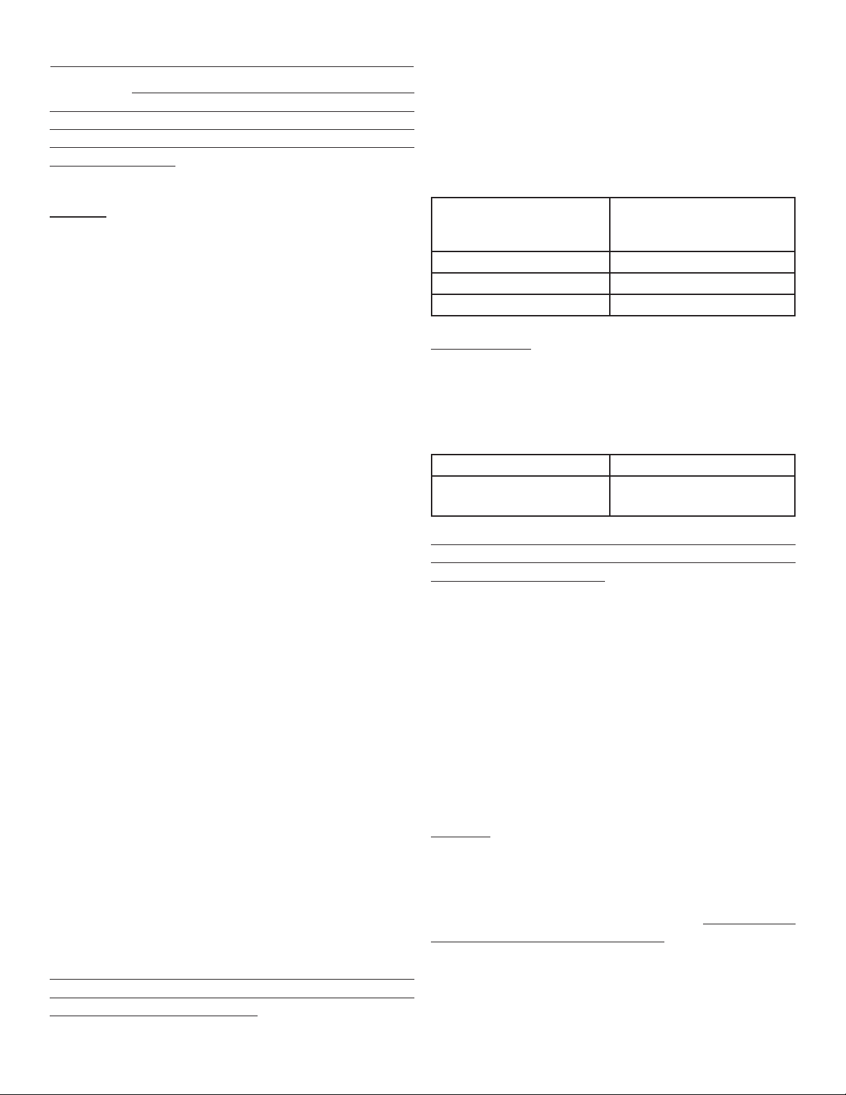
VALVE
INVENTORY
QUANTITY
6386 1
6CG7 1
6AL5 1
Pilot Lamp
A pilot lamp is provided to indicate when mains power is
active. An incandescent light bulb is housed within a bayonet
type lamp xture, and like any bulb, it may need to be re-
placed from time to time.
BULB TYPE SPECIFICAITON
Dial Lamp #47 or equiva-
lent LED replacement
T-3-1/4, 6.3V, .15A, Bayo-
net Base
Only once the unit has been fully disconnected from power,
by disconnection of the IEC cable from the equipment chas-
sis, may the bulb be replaced.
To replace the pilot lamp light bulb, rst remove the lamp
cover. In an anticlockwise motion, gently unscrew the cover
to reveal the light bulb.
To free the light bulb from the bayonet style base, using a
thumb, gently press the light bulb inwards and rotate it anti-
clockwise until it is released.
Once the failed light bulb has been removed, place the new
bulb in to the xture and again, using a thumb, gently apply
pressure to the light bulb, and rotate it in a clockwise motion
until the light bulb is fastened in place.
Warning: If the bulb is pressed inwards with too much pres-
sure, the bayonet lamp cradle may bend and the light bulb will
not illuminate when mains power is present.
If the bayonet lamp cradle is suspected of being bent, it may
be easily remedied from inside the chassis — only after pow-
er has been disconnected form the unit —, by gently applying
pressure to bend it back into form.

12RS660-101022
Circuit Protection
Protection of the circuit has been accounted for by way of a
.25 Amp (250mA) 250V SLO-BLO fuse, which is accessible by
means of a bayonet style fuse assembly, located on the rear
of the chassis.
If a fuse is suspected of having been blown, rst disconnect
power from the unit prior to removing the fuse assembly cap.
Once power has been disconnected form the unit, rotate the
fuse assembly cap anticlockwise until it is unfastened.
Remove the fuse from the cradle and visually inspect it for an
unbroken path.
If the fuse path has been broken, the fuse must be replaced
with a working fuse and the fuse assembly cap securely refas-
tened prior to restoring power.
If the condition of the fuse cannot be visually veried, con-
tinuity of the fuse can be tested by means of a multimeter.
TECHNICAL SPECIFICAITONS
RS660 COMPRESSOR
Channels Mono (stereo linkable)
Circuit Type Valve (6386, 6CG7,6AL5)
INTERCONNECTIONS
Input XLR (pin 2 hot, transformer
balanced), Impedance 15k
Ohms
Output XLR (pin 2 hot, transformer
balanced), Impedance
200/600 Ohms, switchable
Link ¼” mono (tip – CV, sleeve
– 0v)
CONTROL SET
Input Variable potentiometer,
stepped optional
Output Variable potentiometer,
stepped optional
Link Switchable defeat/bypass
Compressor mode THD, Limit, Comp
(switched)
Time Constant Selectable, 7 positions
(stepped switch)
Output Impedance Selectable, 200/600 Ohms,
(toggle switch)
POWER
Internal 120V/220V (preset for
region)
MISC.
Fuse Type .25 Amp (250mA) 250V
SLO-BLO
Pilot Lamp Dial Lamp #47, T-3-1/4,
6.3V, .15A, Bayonet Base or
similar spec. LED
OUTPUT
MAINS VOLTAGE
110-120V
220-240V
E
M I L
T
D
...
E
R
S
P
M
O
R
S
O
C
R
T
0
Y
P
E
S
6
6
FUSE .25 AMP
SLO BLO
FUSE

13RS660-101022
SERVICE
United States
Prior to sending in equipment for repair, please contact our
shop at the number below. We will assist you in trouble-
shooting, and if needed, we will issue an RMA# to return the
equipment for service.
Send Repairs To:
Chandler Limited, Inc.
Attention: Repairs
222 S. Cherry St.
PO Box 38 (if sending via the postal service)
Shell Rock IA 50670
Phone: (319) 885-4200
Email: [email protected]
International
Repair of Chandler Limited products purchased, outside of
the United States, is provided by local or regional authorized
Chandler Limited distributors. To obtain service or repairs,
please contact your local dealer or regional distributor for
further instruction.
Visit chandlerlimited.com for a list of authorized International
Distributors.
CE CERTIFICATION
Chandler Limited declares under its sole responsibility that all
products manufactured by them are in compliance with Elec-
tromagnetic Compatibility (EMC) Directive 2014/30/EU;
Standards: EN55103-1:2009+A1:2012; EN55103-2:2009;
EN55013:2013 and Low Voltage Directive (LVD) 2014/35/
EU; Standards: EN60065:2002+A1:2006+A11:2008+A2:20
10+A12:2011.

14RS660-101022
PRODUCT LIMITED WARRANTY
During the rst year from the date of the original purchase, this product is warranted to be free from defects in materials and
workmanship under normal use, service and maintenance. This warranty applies to the original purchaser and is subject to
the following terms and conditions:
What Is Covered: The product’s components as originally installed by the manufacturer that are defective in materials or
workmanship under normal use, service and maintenance.
What Is Not Covered By This Warranty: This warranty does not extend to or cover:
1. Any defect due to the negligence of others; failure to install, operate or maintain the product properly; unreasonable use;
accidents; alteration; use of unauthorized or non-standardized parts; acts of God; theft; vandalism; electrical malfunctions (i.e.,
resulting from power surges, shorted or overloaded circuits, etc.), use of any power source other than supplied by manufacturer;
repair by anyone other than an authorized Chandler Limited representative; or damage resulting from improper packing or
mishandling by a shipper.
2. Normal wear and tear of parts.
3. Shipping, handling, packaging and delivery costs of the product.
Who Is Covered: The original purchaser.
Repair During The First Year: During the rst year, all defective product components that are covered by this Limited
Warranty will be repaired free of charge including parts and labor. The purchaser will pay shipping costs AND a $35 handling
fee per unit.
WhatYou Must Do for Warranty Service (in the United States): If you live in the United States and your product
was purchased through a U.S. Dealer, please contact your dealer OR call 319-885-4200 or e-mail support@chandlerlimited.
com.
WhatYou Must Do for Warranty Service (outside of the United States): For warranty service if you live outside
of the United States, please contact the dealer where you purchased the product.
Any products returned to Chandler Limited for repair should include: (1) complete description of the problem; (2) name,
address, phone number, fax number, and/or e-mail address; (3) receipt of original purchase; (4) power supply and all acces-
sories and cables. The purchaser is responsible for the shipping costs to and from Chandler Limited. Chandler Limited is
not responsible for damage resulting from improper packing and/or mishandling by a shipper.
If sent by UPS or Federal Express, ship to: Chandler Limited, 222 South Cherry Street, Shell Rock IA 50670
If sent by Postal Service, ship to: Chandler Limited, PO Box 38, Shell Rock IA 50670
The foregoing expresses Chandler Limited’s obligations and liabilities with respect to the quality of the product, its compo-
nents and accessories. All other warranties, express or implied, including the warranties of merchantability or tness for a
particular purpose are disclaimed. Chandler Limited shall not be liable for the loss or use of the product, its components and
accessories, inconvenience, loss or any other damages, direct or consequences arising out of the use of, or inability to use the
product or its components or damages resulting from or attributable to defects in the products or its components. No one
other than Chandler Limited has authority to extend or modify the terms of this limited warranty in any manner whatsoever.

15RS660-101022
DISCLAIMER OF WARRANTY
EXCEPT FOR THE FOREGOING WARRANTIES, CHANDLER LIMITED HEREBY DISCLAIMS AND EXCLUDES ALL
OTHER WARRANTIES, EXPRESS OR IMPLIED, INCLUDING, BUT NOT LIMITED TO ANY AND/OR ALL IMPLIED
WARRANTIES OF MERCHANTABILITY, FITNESS FOR A PARTICULAR PURPOSE AND/OR ANY WARRANTY WITH
REGARD TO ANY CLAIM OF INFRINGEMENT THAT MAY BE PROVIDED IN SECTION 2-312(3) OF THE UNIFORM
COMMERCIAL CODE AND/OR IN ANY OTHER COMPARABLE STATE STATUTE.
LIMITATION OF LIABILITY
THE LIABILITY OF CHANDLER LIMITED, IF ANY, AND PURCHASER’S SOLE AND EXCLUSIVE REMEDY FOR DAM-
AGES FOR ANY CLAIM OF ANY KIND WHATSOEVER, REGARDLESS OF THE LEGAL THEORY AND WHETHER
ARISING IN TORT OR CONTRACT, SHALL NOT BE GREATER THAN THE ACTUAL PURCHASE PRICE OF THE
PRODUCT WITH RESPECT TO WHICH SUCH CLAIM IS MADE. IN NO EVENT SHALL CHANDLER LIMITED BE
LIABLE TO PURCHASER FOR ANY SPECIAL, INDIRECT, INCIDENTAL, OR CONSEQUENTIAL DAMAGES OF ANY
KIND INCLUDING, BUT NOT LIMITED TO, COMPENSATION, REIMBURSEMENT OR DAMAGES ON ACCOUNT OF
THE LOSS OF PRESENT OR PROSPECTIVE PROFITS OR FOR ANY OTHER REASON WHATSOEVER.
Table of contents
Other Chandler Limited Air Compressor manuals

Popular Air Compressor manuals by other brands


Ingersoll-Rand
Ingersoll-Rand R4-11 kW Product Maintenance Information

Clarke
Clarke XE10/100 Operation & maintenance instructions

Parkside
Parkside PKZ 180 B2 Translation of the original instructions

CVS
CVS RKL 160 Mounting instructions

Alesis
Alesis 3630 Service manual

Gardner Denver
Gardner Denver ELECTRA-SAVER ESMF Operating and service manual


