2
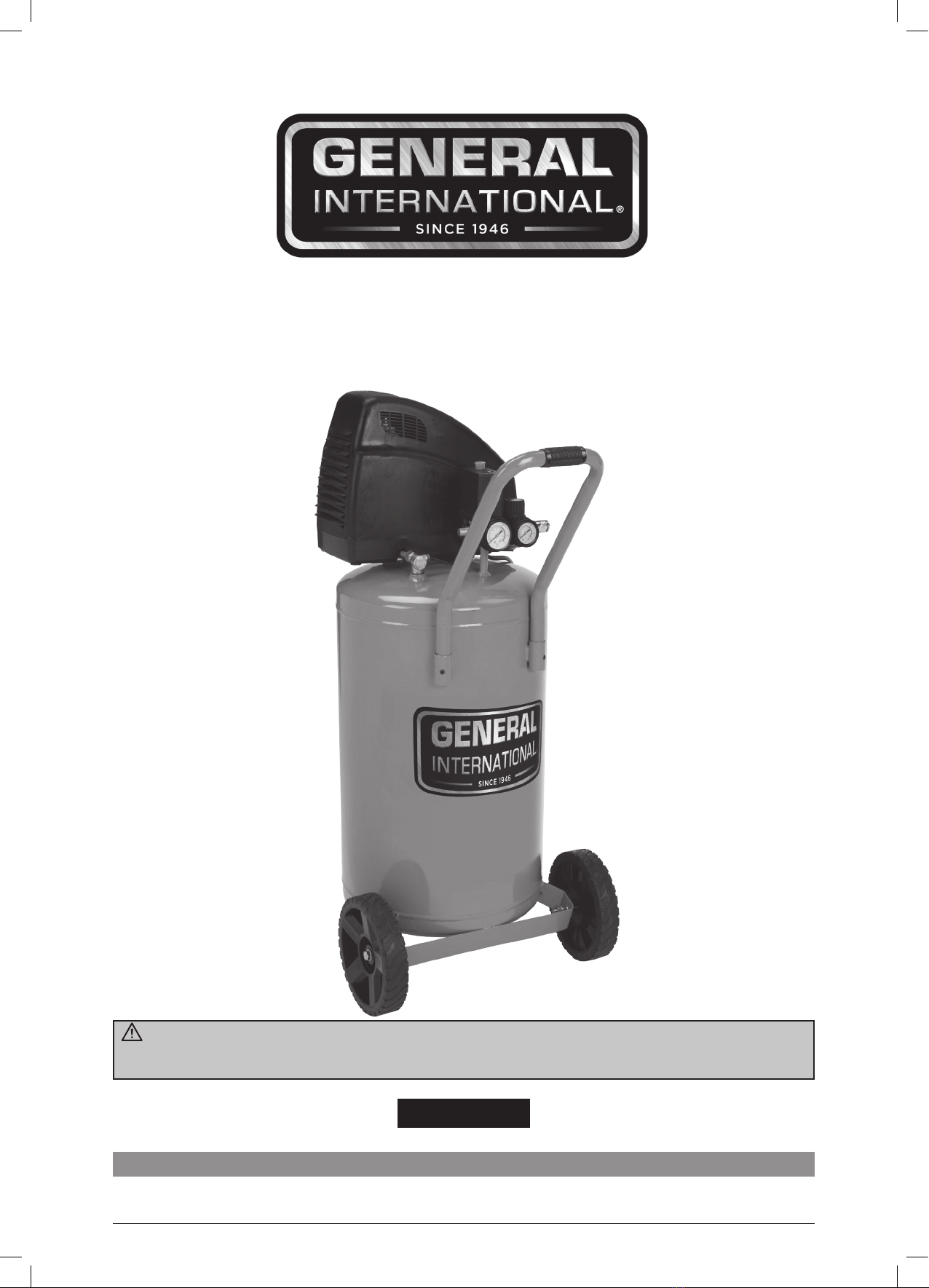
General International
Thank you very much for choosing a General International product!
For future reference, please complete the owner’s record below:
Serial Number/Lot Date Code:
Purchase Date:
Save the receipt, warranty, and this manual. It is important that you read the entire manual to become
familiar with this product before you begin using it.
This air compressor is designed for certain applications only. General International is not responsible for
issues arising from modication or improper use of this product such as an application for which it was not
designed. We strongly recommend that this product not be modied and/or used for any application other
than that for which it was designed.
THANK YOU
for choosing this General International machine. This tool has been carefully tested and inspected before
shipment and if properly used and maintained, will provide you with years of reliable service. To ensure
optimum performance and trouble-free operation, and to get the most from your investment, please take the
time to read this manual before assembling, installing and operating the unit.
The manual’s purpose is to familiarize you with the safe operation, basic function, and features of this
tool as well as the set-up, maintenance and identication of its parts and components. This manual is not
intended as a substitute for formal woodworking instruction, nor to oer the user instruction in the craft of
woodworking. If you are not sure about the safety of performing a certain operation or procedure, do not
proceed until you can conrm, from knowledgeable and qualied sources, that it is safe to do so.
Once you’ve read through these instructions, keep this manual handy for future reference.
GENERAL®INTERNATIONAL WARRANTY
All component parts of General®International products are carefully inspected during all stages of production
and each unit is thoroughly inspected upon completion of assembly.
2-Year Limited Warranty
All products are warranted for a period of 2 years (24 months) from the date of purchase. General®
International agrees to repair or replace any part or component which upon examination, proves to be
defective in either workmanship or material to the original purchaser during this 2-year warranty period,
subject to the “conditions and exceptions” as listed below. Repairs made without the written consent of
General International will void the warranty.
Disclaimer
The information and specications in this manual pertain to the unit as it was supplied from the factory at
the time of printing. Because we are committed to making constant improvements, General International
reserves the right to make changes to components, parts or features of this unit as deemed necessary,
without prior notice and without obligation to install any such changes on previously delivered units.
Reasonable care is taken at the factory to ensure that the specications and information in this manual
corresponds with that of the unit with which it was supplied. However, special orders and “after factory”
modications may render some or all information in this manual inapplicable to your machine. Further, as
several generations of this tool model and several versions of this manual may be in circulation, if you own
an earlier or later version of this unit, this manual may not depict your machine exactly. If you have any
doubts or questions contact your retailer or our support line with the model and serial number of your unit for
clarication.
To le a Claim
To le a claim under our Standard 2-year Limited Warranty, all defective parts, components or machinery
must be returned freight or postage prepaid to General®International, or to a nearby distributor, repair center
or other location designated by General®International. For further details contact our service department:
USA toll-free (844) 877-5234 or (419) 877-5234 or through our websites: www.gipowerproducts.com and
www.general.ca. Along with the return of the product being claimed for warranty, a copy of the original proof
of purchase and a “letter of claim” must be included (a warranty claim form can also be used and can be
obtained, upon request, from General®International or an authorized distributor) clearly stating the model
and serial number of the unit (if applicable) and including an explanation of the complaint or presumed defect
in material or workmanship.
Conditions and exceptions
This coverage is extended to the original purchaser only. Prior warranty registration is not required but
documented proof of purchase, i.e. a copy of original sales invoice or receipt showing the date and location
of the purchase as well as the purchase price paid, must be provided at the time of claim.
Warranty does not include failures, breakage or defects deemed after inspection by General®International
to have been directly or indirectly caused by or resulting from; improper use, or lack of or improper
maintenance, misuse or abuse, negligence, accidents, damage in handling or transport, or normal wear and
tear of any generally considered consumable parts or components.
Repairs made without the written consent of General®International will void all warranty.