Devantech dS2824 User manual

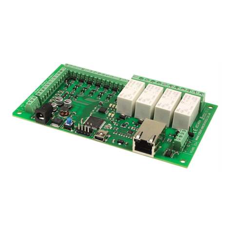
dS2824
dS2824 User Manual v4.12
Table of Contents
Documentation history.................................................................................................................4
A quick look...............................................................................................................................5
Introduction...............................................................................................................................6
Getting started...........................................................................................................................7
ocating the IP Address...............................................................................................8
Configuring the dS2824.............................................................................................................10
Status page.............................................................................................................11
Network page...........................................................................................................12
Webpage security.............................................................................................................13
TCP/IP page.............................................................................................................15
Configuring relays.....................................................................................................17
Relay automation.....................................................................................................18
Input/Output configuration........................................................................................21
Connecting I/O to Virtual Relays.........................................................................................22
dSx Configuration.....................................................................................................23
dSx Mapping Table............................................................................................................24
dSx Example....................................................................................................................26
Sequencer...............................................................................................................28
Sequencer commands.......................................................................................................29
K Outputs........................................................................................................................30
Sequencer Examples.........................................................................................................30
Schedules................................................................................................................35
Counter/Timers........................................................................................................37
Event Notifications....................................................................................................40
Node-RED........................................................................................................................41
Peer to Peer.............................................................................................................42
Email notifications....................................................................................................43
Pinging remote machines...........................................................................................44
Repeat Time....................................................................................................................44
Attempts.........................................................................................................................44
Delay..............................................................................................................................45
Ping Time........................................................................................................................45
Rebooting the target machine.............................................................................................45
The application page..................................................................................................................46
Application page security...........................................................................................47
Accessing your webpage from the internet...................................................................48
Boolean equations.....................................................................................................................49
TCP/IP command sets................................................................................................................51
ASCII command set..................................................................................................51
Binary command set.................................................................................................53
AES binary command set...........................................................................................56
Modbus commands...................................................................................................58
Function 01 (0x01) Read Coils............................................................................................58
Function 04 (0x04) Read Input Registers..............................................................................58
Function 05 (0x05) Write Single Coil....................................................................................59
Function 15 (0x0F) Write Multiple Coils................................................................................59
Error code 1.....................................................................................................................59
Copyright © 2016-2021, Devantech td.
All rights reserved. www.robot-electronics.co.uk 2

dS2824
dS2824 User Manual v4.12
Error code 2.....................................................................................................................59
Error code 3.....................................................................................................................59
Modbus Gateway......................................................................................................59
oading the application firmware.................................................................................................60
Erasing old configuration settings...............................................................................62
dS2824 hardware......................................................................................................................63
ED indication..........................................................................................................64
Power supply...........................................................................................................64
Operating temperature..............................................................................................64
Power relays............................................................................................................65
Analogue/Digital flexible I/O's....................................................................................66
Connection examples.................................................................................................................66
Temperatue sensor...........................................................................................................67
Power supply input voltage................................................................................................67
Analogue channels............................................................................................................67
Serial port connections..............................................................................................69
dS2824 dimensions...................................................................................................................70
Notes...................................................................................................................................... 71
Copyright © 2016-2021, Devantech td.
All rights reserved. www.robot-electronics.co.uk 3

dS2824
dS2824 User Manual v4.12
Documentation history
v4.01 Major update to the underlying dScript, now with functions and local variables.
Added “From Address” for easymail emails.
v4.02 Bug fixes for the underlying dScript.
v4.03 Editor update, added support for multiple editor tabs.
Compiler update, added support for multiple files in project.
Compiler update, added support for #ifdef, #else, #endif
v4.04 TCP server socket now transmits keepalives when connections become dormant
for 10 seconds. 6 unacknowledged packets at 10 second intervals will result in
port closure.
V4.05 Added phone app support (IO Network 2 on the App stores). Fixed bug that caused
intermittent module not found error on firmware update.
V4.06 Added system reboot button to config status screen.
dScript updated to support dS2832. See dScript-v4.xx manual.
V4.07 Added new features:
Ping Used to ping other machines to check if responding.
Sequencer Added a 120 step, 12 output sequencer
v4.08 Added display of MAC address to network configuration page.
Bugfix – NTP (Real time clock) startup failed under some circumstances.
Renamed command “counters” to “setcounters”.
V4.09 Added 3 new commands to Binary and AES Binary command set, to
control all relays in one command. Set all, set selected and clear selected.
V4.10 Added support for dSx42 extension modules.
v4.11 Added Event Notifications, sends message to remote computer.
v4.12 Bugfix – Adding steps to the sequencer could crash the board.
Note: If you have a custom app based on app-dSxxxx-v4-07 or earlier, you will need to re-
name the “counters” command to “setcounters” for it to compile with this version.
Copyright © 2016-2021, Devantech td.
All rights reserved. www.robot-electronics.co.uk 4

dS2824
dS2824 User Manual v4.12
A quick look
Ethernet connected module, 10/100Mb auto negotiated.
Relays – 24 x 16Amp 250Vac C/O.
I/O – 8 x flexible I/O's NPN output, Volt free input or 12-bit analogue input.
Power – 12VDC 1.5Amp supply required. 2.1mm center positive.
Connections – Screw Terminals for N/O N/C and Common contacts
PCB size – 249mm x 123mm
Controlled graphically by secure webpage or optionally one of ASCII, Binary or Modbus com-
mand sets over TCP/IP.
Email notifications – 8 selectable notifications, up to 100 emails/hour max.
Peer to Peer – Control relays on other modules.
Notifications – Sends a message when selected I/O change state.
ine powered (up to 300 meter range) extension modules.
Sequencer – Flexible 100 step, 12 output sequencer
Schedules – Able to schedule events based on time of day/week
Counter/Timers – Count or time events. 10 counts/second Max.
Also available when optionally programming in dScript is a TT level serial port and an RS485
serial port.
Copyright © 2016-2021, Devantech td.
All rights reserved. www.robot-electronics.co.uk 5

dS2824
dS2824 User Manual v4.12
Introduction
The dS2824 is an Ethernet connected relay module featuring 24 channels of 16Amp 250Vac re-
lays. Each relay has both normally open (NO) and normally closed (NC) as well as the common
available on three terminals.
In addition to the relays, the dS2824 has 8 flexible I/O channels which may be individually
configured to be:
1. NPN transistor output.
2. Active low input with pull-up (allows direct connection of volt free contacts).
3. Active low input without pull ups (easy to connect logic level inputs).
4. Analogue 12-bit inputs using a 4.096v reference (0v-4.096v input range).
5. Analogue 12-bit inputs using a 5v reference (0v-5v input range).
The dS2824 requires a 12v 1.5Amp power supply such as this one:
http://www.robot-electronics.co.uk/universal-12vdc.html
The dS2824 has four built in control methods.
Primary control method is graphically by using its built in secure website.
Secondary control may be one of:
ASCII - type in commands via a program such as PuTTY.
Binary - Command set using binary codes
Modbus – Functions 1, 4, 5 and 15 supported
And if you should wish to modify the supplied firmware – you can.
Behind the scenes there is dScript, a powerful multi-threaded operating system and program-
ming language. The supplied firmware is written in dScript as well as HTM , CSS and
Javascript on the webpages and the full source is in the separately down-loadable dScript sup-
port package.
You do not need to use dScript at all, but its great to know its there - just in case you do.
Copyright © 2016-2021, Devantech td.
All rights reserved. www.robot-electronics.co.uk 6

dS2824
dS2824 User Manual v4.12
Getting started
Start by plugging in the Ethernet cable to connect the module to your network, and the 12v
jack plug from your adapter. Switch on and the first thing you will note is that the blue ED will
flash 3 times. This indicates that the control firmware is loaded on the module. (If the blue led
does not flash you will need to load in the control firmware. Don't worry, this is very easy to
do. Just go to the chapter on installing the firmware and follow the instructions there).
If you are using a Win7/8/10 PC, open your browser and into the address bar (not the search
bar) type:
http://dS2824/index.htm
You should now see the application webpage and you can control relays and I/O's.
Copyright © 2016-2021, Devantech td.
All rights reserved. www.robot-electronics.co.uk 7

dS2824
dS2824 User Manual v4.12
Locating the IP Address
If you are not using a windows PC then you will need to find the IP address of the module.
The simplest method is connect the module (Ethernet, USB then lastly, Power) and load up the
dScript editor.
Go to Module Select Port and make sure the correct serial port is selected as illustrated above.→
Now go to Module IP Address and the current IP address is displayed.→
Make sure the Ethernet is connected before you apply power. If you plug the Ethernet cable in
after the power, the module will already have booted with a default IP address.
Alternatively, if you have a DHCP server on your network (your router is normally the DHCP
server) then the dS2824 will get its IP address from that. og on to your router and navigate
to the AN client list.
Above is the entry from our ASUS RT-N66U router. So now you type:
192.168.0.9/index.htm
into your browser address bar and you should see the application webpage shown on the pre-
vious page.
Copyright © 2016-2021, Devantech td.
All rights reserved. www.robot-electronics.co.uk 8

dS2824
dS2824 User Manual v4.12
If you prefer, you can download a java program that will run on Windows, MAC or inux, and
will list all of our modules that are connected to your AN. DevantechModuleFinder.jar
If you do not have a DHCP server the dS2824 will use a default IP address of 192.168.0.123 so
make sure your PC is on the same subnet of 255.255.255.0 and its IP address is
192.168.0.xxx
Copyright © 2016-2021, Devantech td.
All rights reserved. www.robot-electronics.co.uk 9

dS2824
dS2824 User Manual v4.12
Configuring the dS2824
There are a set of configuration pages to get the dS2824 operating as you want it. These
pages are all _configx.htm, (that's a leading underscore character).
ie.
_config.htm
_config2.htm
Anything that starts with _config is considered a special name for configuration pages and can
only be seen if you have the the USB cable plugged in and connected to your PC.
Why only if the USB cable is plugged in?
Its an additional security measure. After you have configured and deployed the module, you
really don't want these configuration pages available for others to change. So with the USB ca-
ble disconnected the _config pages are not available. If you try to access them you just get
served a “not authorised” page instead.
So for now, you do want to look over the config pages. If you have a Win10, inux or MAC PC,
you can go right ahead and plug in the USB cable. These machines will install their own USB
drivers. We won't be sending anything to the board, its just the presence of the USB connec-
tion that enables the config pages to be served. If you have a Win7 or Win8 PC you will need
to install the drivers. (go to the chapter on installing the firmware and follow the instructions
there).
With the USB cable connected, browse to:
192.168.0.9/_config.htm
(substituting your IP address)
Copyright © 2016-2021, Devantech td.
All rights reserved. www.robot-electronics.co.uk 10

dS2824
dS2824 User Manual v4.12
Status age
You should now see the following page:
This status page shows you the system and application firmware revisions as well as the sup-
plied voltage to the board and its internal temperature.
If you hover your mouse cursor over the menu buttons on the left, the help panel will give you
an overview of each one.
The system reboot button should be used with caution. If the module is at a remote site and
you change the IP address, you may not be able to reach it again.
Copyright © 2016-2021, Devantech td.
All rights reserved. www.robot-electronics.co.uk 11

dS2824
dS2824 User Manual v4.12
Network age
Notice that everything below the Host Name is greyed out and can't be changed. This is be-
cause the “Enable DHCP” box is checked and all the greyed out fields are supplied by the DHCP
server. Although a quick way to get you connected, we really do not recommend this as the
DHCP server can assign a different IP each time you power up. If you want to control this mod-
ule from the internet while you are away from the premises then you will be setting up port
forwarding on your router which requires a fixed IP address.
So lets do that first.
Uncheck the DHCP box and you can then set all the other fields. Notice that the Red “Update
Pending” light comes on. It indicates there are changes which have not yet been written to the
flash memory. It will go off again 5 seconds after you stop changing anything.
Choose an IP address for the module, something outside of the DHCP settings on your router
so it will not assign anything to that address. The subnet mask, Gateway and DNS can all be
left as the defaults. Network changes only take effect after the next re-boot, so wait until the
“Update Pending” light goes out and give the reset button on the module a quick press. The
Green ed will light and the Blue led will flash 3 times. You will now find the module at your
new IP address. If the Red led comes on after you press the reset button, its because you
pressed it for too long (and entered bootloader mode). Just have another go with the reset
button for a bit less time.
Your browser won't know you have changed the IP address so it will still be showing the old,
Copyright © 2016-2021, Devantech td.
All rights reserved. www.robot-electronics.co.uk 12

dS2824
dS2824 User Manual v4.12
now dead page. Make sure you change to your new IP address and load the page again.
Web age security
The webpage security section allows you to prevent unauthorised personnel from accessing the
application webpage or using it to control the module.
eaving the Security Password blank will disable it and allow everyone to access the application
page to control the module.
To enable password protection enter a password into the Password box. You can use any char-
acters from the ASCII character set from 0x20 to 0x7E except “ (0x22). It may be up to 200
characters long and you don't have to memorise it, so make it a long one with plenty of upper-
case, lowercase, numbers and symbols.
Accessing a special webpage, _pw.htm, will install the password on your browser. To do this
make sure the Enable _pw.htm box is checked.
When the “Update Pending” light goes out, re-boot the module and go to yourIP/_pw.htm
You will see something like this:
The password is now loaded on your browser. Do the same for any further browsers you want
to enable. When you have done uncheck the “Enable _pw.htm” box to prevent anyone else
Copyright © 2016-2021, Devantech td.
All rights reserved. www.robot-electronics.co.uk 13

dS2824
dS2824 User Manual v4.12
from loading the password. When the “Update Pending” light goes out re-boot the module
again.
The default port used by html webpages is 80. You can change this if required. If you do so
then you will need to include the port number in the address.
If you change the port to 2345 then the webpage will be at:
YourIP:2345/index.htm
For example:
192.168.0.123:2345/index.htm
Copyright © 2016-2021, Devantech td.
All rights reserved. www.robot-electronics.co.uk 14

dS2824
dS2824 User Manual v4.12
TCP/IP age
The TCP/IP tab allows you to select one of three command sets to control the module. These
are independent of, and separate to the HTM webpage control.
Clicking on one of the four check boxes will select that command set. Only one command set
may be selected. You can disable all TCP/IP command sets by clicking on an already selected
box.
The ASCII command set is text based. You can use any program that can send text over TCP/
IP. We use PuTTY in raw mode. The Binary command set operates in a similar way to our
ETHxxx range of boards (but uses different commands), by sending binary commands to the
module. AES Binary adds encryption. Note the AES key MUST be 32 bytes long. We have test
applications written in C# and Java to demonstrate AES encryption.
Phone App confiqures the module for control with our “IO network 2” app, available on
iTunes/Play store. Password is an 8 character password used only with the App. Change this to
a password of your choice and use the same password on your phone.
Copyright © 2016-2021, Devantech td.
All rights reserved. www.robot-electronics.co.uk 15

dS2824
dS2824 User Manual v4.12
When selecting the Modbus commands, an additional set of configuration boxes are available.
These allow you to select the UID, normally you will leave this at the default of 1. The dS2824
will respond to commands on this UID. If you send any other UID it will be treated as the ad-
dress of a Modbus module connected to the RS485 port. Commands to other UID’s will be con-
verted to Modbus RTU format and sent out on the RS485 port. Any responses will be converted
back to Modbus/TCP format and returned to you.
The second box selects the baud rate of the Modbus RTU line and the third box selects even,
odd or no parity.
The Modbus command set implements functions 1, 4, 5 and 15.
When selecting the Modbus command set, make sure you select port 502 which is the official
port number for Modbus over TCP/IP.
A full description of the commands is in the “Command Sets” section later in this manual.
Important – If you want to use extension modbus modules over the RS485 bus, make sure the
“Enable dSx” checkbox on the dSx Config page is unchecked, then reboot the module.
Copyright © 2016-2021, Devantech td.
All rights reserved. www.robot-electronics.co.uk 16

dS2824
dS2824 User Manual v4.12
Configuring relays
The next two tabs allow you to set the names of the 32 relays that will be displayed on the ap-
plication page.
Use the Relay No. box to select the relay to configure. There are 32 relays available. Relays 1-
24 are the physical relays on the module. Relays 25-32 are virtual relays, they have no physi-
cal presence but otherwise behave the same as the real ones. I/O lines may be linked to vir-
tual relays to provide additional physical outputs, see next section for details.
Names may be up to 20 characters long,but keep them shorter if you want to use a phone as
the controller. Here we have renamed relay 1 as “Yard ights” and those 10 characters are a
comfortable size on a vertical phone screen.
Copyright © 2016-2021, Devantech td.
All rights reserved. www.robot-electronics.co.uk 17

dS2824
dS2824 User Manual v4.12
Relay automation
There are a set of control boxes that provide for autonomous relay operation. If you just want
to control the relays from the webpage or using one of the TCP/IP modes, then leave these
boxes blank.
Relay No. box
This selects the relay you wish to configure. There are 32 relays available. The first 24 relays
are the actual relays on the module. Relays 25-32 are virtual relays. They have no physical
presence but otherwise behave identically to the real ones. They can provide additional pro-
cessing and a larger control surface to your application.
Pulse/Follow box
If you place a number in this box then that is the pulse time for the relay in mS (1000mS = 1
second). The minimum value is 100mS. The maximum is 2147483647 (more than 24 days).
When the relay is toggled on, timing begins and at the end of the time period the relay goes
off again. If the button is pressed again during timing then the timing is restarted.
The above example will turn off the yard lights after 30 minutes. 1800000 mS is 1800 seconds.
1800 seconds is 30 minutes.
It also possible to insert a boolean equation into the box. Boolean equations are just simple
equations that evaluate to a 0 or 1.
For example Relay 1 is referred to a R1. Input1 is referred to as D1 (Digital 1). Analogue input
1 is referred to as A1.
Copyright © 2016-2021, Devantech td.
All rights reserved. www.robot-electronics.co.uk 18

dS2824
dS2824 User Manual v4.12
Here's a very simple example:
Enter R2 into the Relay 1 Pulse/Follow box. This will make relay 1 copy whatever you do to Re-
lay 2. Try it!
Now change it to !R1.
The exclamation mark is read as “Not R1”. Now relay 1 will always be the opposite of relay 2.
Try it.
Boolean equations may be used for controlling relays and other objects such as email.
See the “Boolean equation” section later in this manual for full documentation.
Copyright © 2016-2021, Devantech td.
All rights reserved. www.robot-electronics.co.uk 19

dS2824
dS2824 User Manual v4.12
Set Reset & Toggle boxes
When used, these three controls contain boolean equations. The “Set Relay” box will set the
relay when the boolean equation becomes true. The other two boxes reset and toggle the relay
when the boolean equation become true.
This is important! The Set, Reset and Toggle controls are transitory (edge triggered) controls.
The relays are only affected at the moment the boolean equation becomes true. This differs
from the Follow box where the relay continuously follows the output state of the equation.
In the previous example where we placed R2 in relay 1’s Follow control, relay one will always
be the same as relay 2. If relay 2 is off and we click relay 1 (Yard ights) nothing will happen.
However if we want relay1 to be controlled by relay 2 as above, and also want to be able to
toggle it on/off from the webpage, we can put R2 in the “Set Relay” box and !R2 in the “Reset
Relay” box.
Try it.
Power-up restore
When checked, the relay is restored to the previous state it had when power was lost. If the
relay was on when power was lost or the module was turned off, then the relay will be turned
on when the module is powered up again.
Copyright © 2016-2021, Devantech td.
All rights reserved. www.robot-electronics.co.uk 20
Other manuals for dS2824
2
Table of contents
Other Devantech Computer Hardware manuals
Popular Computer Hardware manuals by other brands
RF Player
RF Player RFP1000 user guide
TRENDnet
TRENDnet TEW-621PC - 300Mbps Wireless N PC Card... Specifications

Vantec
Vantec Slot Protector Kit SPK-08UV-BK datasheet
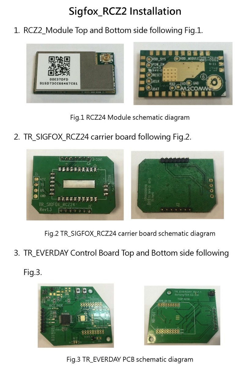
Oyster
Oyster Sigfox RCZ2 Installation

Kontron
Kontron KISS Stor Slim Quick installation guide

VIA Technologies
VIA Technologies VAB-3000 user manual

