devention Scout X4 User manual

Scou tX4
cleUention
•
Auto Take off
•
Auto Landing
•
Follow me mode
•
Circle flight
•
Fence flight
•
Single Waypoint flight
•
Altitude hold mode
•
One key Return To Home
•
Automatic Cruise
•
IOC mode
•
Backtracking
•
Waypoint record
Match with GCS Ground Station Software
Quick Start Guide and Systems Flowchart
•
Specifications:
Main Rotor Dia. : 233mm
Overall (L x W x H); 335 x 335 x 275mm
Weight: 1770g(Battery included)
Takeoff Weight: <2270g
Transmitter: DEVO FI2E
Receiver: DEVO-RX707(CE) I RX709(FCC)
Brushless Motor: WK-WS-34-002
Brushless ESC: WST-16AI-1 (RIG)
Main Controller: FCS-X4
Battery: 22.2V 5400mAh Li-Po
Ground Station: GCS
2.4G Bluetooth Datalink: BT-2401A(FCC) / 2401B(FCC)
BT-2402A(CE) / 2402B(CE)
•
M1/M3 rotate in clockwise, motors are the levogyrate thread.
•
M2/M4 rotate in counterclockwise, motors are the dextrogyrate thread.
•
When assemble the propellers, rotating direction is oppsite to the arrow direction, the directions are the same when take down the propellers.

Contents
1.0 Devices that support Ground Station: Android and Apple phone
1
2.0 Download and install software
1
3.0 Installing the Propellers
1
4.0 Restore or assemble the skid landing/binding the radio
1-2
5.0 Main screen instructions
.3
6.0 Airline compilation illustration
.3
7.0 Compass Calibration
.4
8.0 G-3D 3-axis brushless Gimbal installation
.4
9.0 Installing the iLook+ 1080p camera with 5.8ghz video link
5
10.0 Motor Unlock
5
11.0 Motor Lock
.5
12.0 GPS indicator lights
6
13.0 Function and rocker control interface description
6-8
14.0 2.4G Bluetooth Datalink
9-13
15.0 Ground station firmware setting
14-16
16.0 FCS-X4 Main controller guideline
17
17.0 DEVO RX707/RX709 Receiver guideling
17

4
A
M3
M2
1.0 Devices that support Ground Station: Android and Apple phone
Android phone requirements:
(1)
The Android version should be 4.0 or above, the screen resolution should be 480 x 800 pixels or above.
(2)
Google play, google play store and TTS firmwares should be preinstalled in the phone.
2.0 Download and install software
(1)
Please download the "GCS
Ground Station"
software from walkera official web (www.walkera.com
) / Google for Android version 4.0 above.
(2)
Apple IOS system, Please download the
"GCS Ground Station"
software from APP Store.
Suggestion: please set the phone to flight mode when you are using the GCS firmware to control the flight.
3.0 Installing the Propellers
r% •
Q •
3.1 Prepare forward propeller
(Clockwise arrow mark), counter
propeller (counterclockwise
arrow mark )
3.2 Match the arrows on the
propellers to the arrows on the
arm next to each motor. Screw
each propeller onto the motor,
secure by hand, no need for tools.
3.3 Prepellers assembled
(assembled skid landing)
3.4 Prepellers assembled
(unassemble skid landing)
4.0 Restore or assemble the skid landing/binding the radio
4.1
Skid landing assembled(restoration/code binding)
The Landing gear is shipped in the retracted position.
DO NOT try to extend the landing gear by pulling on
it.
We will deploy the landing-gear the first time the system is powered, please follow these instructions carefully.
Powir indicator
I ; ;
Power switch
—
nib/Fr button
Cr— Power
Switch
Vj
Bluetooth
indicator light
,
..:
4--
(Green light)
4.1.1 Install the fully charged
battery DO NOT turn on the
battery until later.
*Please check the charger
manual for charging instructions
4.1.2 Turn X4 on its back. The
belly and the retractable legs
should now be facing up.
MAKE SURE nothing is blocking
the
legs.
4.1.3 Turn the power switch to
"ON" position, and press on the
power button about 3-5 second
till the Green power indicator solid.
4.1.4
Turn on the power switch
(to position ON) of 2.4G Bluetooth
Datalink. The green light of
bluetooth will flash quickly,
waiting for the connection with
the phone bluetooth.
4.1.5 Enter phone settings and open the bluetooth function. In the bluetooth search list find and touch "walkera-****", input password 1234 to connect
and the connection will be successful if it displays "connected". Exit the settings when finished.
•
1 •

Power button__i
V
II
Ptwer Switc
-
I
.
Power indicator
04— Power
Switch
Bluetooth
Indicator light
..!
1—
(Green light)
vi
Touch GCS icon
Touch GO icon
Enter the main screen
Red LED flashing till to go out
means the code binding finished.
Flight Assistant
0
,
\
4.1.6 Touch GCS icon at middle of the mibile screen, GCS software will search automatically and display matched bluetooth, then select the matched
bluetooth and touch GO icon or back to enter into main interface(Skid landing comes back automatically)
Touch GCS icon
Touch GO icon
Enter the main screen
Red LED flashing till to go out
After the successful binding place
means the code binding finished.
the aircraft on a stable surface.
4.2 Skid landing unassembled(assemle skid landing/code binding)
Skid landing
1111.1.1117%:~01
,
Skid landing
Skid landing
module A
module B
....
11,
4.2.1 Prepare two skid landing,
4.2.2 Put the skid landing into
4.2.3 Install the skid landing
4.2.4 Skid landing installation
skid landing module A/B, 4pcs
the skid landing position.
module, and screw down the
finished.
M2.5X20 screws.
M2.5X20 screw to fix skid landing.
h
4.2.5 Put the aircraft on the
horizontal position, slide the
power-switch to the ON position,
then press on the power button for
about 3-5 seconds, until the green
power indicator lights solid.
4.2.6 Turn on the power switch
(to position ON) of 2.4G Bluetooth
Datalink. The green light of bluetooth
will flash quickly, waiting for the connection
with the phone bluetooth.
4.2.7 Enter phone settings and open the bluetooth function. In the bluetooth search list find and touch "waikera-****", input password 1234 to connect
and the connection will be successful if it displays "connected". Exit the settings when finished.
4.2.8 Touch GCS icon at middle of the mibile screen, GCS software will search automatically and display matched bluetooth, then select the matched
bluetooth and touch GO icon or back to enter into main interface.
•
2 •

Return
To Me
Climbing rate
Airline compilation
Setting
Fix the position of aircraft or operator
Stick control and settings
Altitude
Velocity
Battery capacity
Satellite quantity
Flight time
Distance to the
next waypoint
Display/
concealing icon
TO Home
Map selection
Ground speed
5.0 Main screen instructions
Aircraft rolling degree
Aircraft pitching degree
Aircraft steering degree
6.0 Airline compilation illustration
In the main screen, touch Lig icon and enter flight line edit screen. Touch icon Ira to save in the aircraft when finishing editing the flight line.
Position hold function: fix the position
of aircraft or operator
Map selection
Airline recorded into aircraft
Readout airline from aircraft
Airline recorded into phone
►
Readout airline from mobile phone
Waypoint increase
Airline compilation
Waypoint decrease: Hold down the
iconlito clear all waypoints
•
3 •

The red LED light out
te'
i
ad vertical
Ground
down
7.5 NOSE DOWN rotation. Rotate
the aircraft facing the nose down.
rotate smoothly in 90 deg increments.
Pausing 1 second for each 90 deg.
(0 / 901180
1
270 I 360)
7.6 Put aircraft to the horizontal position,
the red LED light out which means
calibration finished. pleasereconnect
the aircraft power after calibration.
7.0 Compass Calibration
In the main screen, touch IN icon then touch mode to enter stick control and setting screen.
Compass calibration icon
IMPORTANT:
Make sure the motors are locked before calibration (Aircraft red LED indicator is NOT flashing). Factory default setting, is for the
motors to be locked after the completed ID binding process. (For details on motor lock and unlock process see point 10 and 11)
7.1 Touch the icon and enter
compass calibration. The red
LED of the aircraft will flash
rapidly.
7.2 FORWARD rotation. Rotate
tilting the aircraft forward rotate
smoothly in 90 deg increments.
Pausing 1 second for each 90
deg.(0 / 90 / 180 / 270 / 360)
7.3 CLOCKWISE rotation. Rotate
the aircraft around the roll axis rotate
smoothly in 90 deg increments.
Pausing 1 second for each 90 deg.
(0 / 90 / 180 /270 / 360)
7.4 HORISONTAL rotation. Rotate
the aircraft around the YAW axis
rotate smoothly in 90 deg increments.
Pausing 1 second for each 90 deg.
(0 /90 / 180/270
1
360)
IMPORTANT: The first couple of flights, you may expereince the
aircraft drifting,
This is normal, please continue to fly the aircraft manually, while the
system inprove the calibration, after 5-10 minutes land, lock the motors,
this will save the improved settings.
Notice: The slight drifting may continue for a couple of batteries, you
will notice significant improvement in the GPShold & stability
after 4-5 batteries.
Notice: Always perform the calibration away from eletric fields and
metal surfaces.
Trivia: Different brands have different calibration processes, the
process is typically refered to as "the Calibration Dance".
8.0 G-3D 3-axis brushless Gimbal installation
IMPORTANT: REMOVE the battery from the Scout X4 while you install the gimbal
The gimbal is a high-performance eletromechanical design and should be handled with great care. AVOID using force when installing.
8.1 Prepare the G-3D gimbal,
M3x12 screw, spring.
8.2 Slide the gimbal unto the quik
mount rail, the gimbal shouldslide
from the front of the aircraft towards
the rear, gently move it as far back
as possible.
8.3 Install the springloaded
M3x12mm "finger screw" at the
front of the gimbal, this will
secure the gimbal.
8.4 Connect the 9pin white data
cable to the "complex data port"
on the bottom of the X4, then
connect the cable to the back of
the G-3D gimbal.
•
4 •

r
Ith
8.5 Make sure the gimbal move f eely in all directions.
The G-3D gimbal is now successfully installed.
9.0 Installing the iLook+ 1080p camera with 5.8ghz video link
9.1 Screw the short "mushroom"
antenna into the camera, use the
included wrench to gently secure
the antenna, do not use force.
9.2 Release the two M2x4 screws
securing the camera mounting
bracket.
9.3 Install the camera into gimbal,
Fix it with camera fixed frame
(ensure the gap close to the
lens), then screw the M2x4
screw to the camera fixed
frame again.
9.4 Connect the cameras power
cable to the power port on the
G-3D gimbal controller.
9.5 The iLook+ camera is now successfully
installed in your G-3D gimbal.
10.0 Motor Unlock
After succeeding in binding the code, under the stable mode, put the throttle control ball in the lowest position, and stir the direction control ball to the far left.
When the red LED indicator turn solid red, it means that the motor is unlocked. In this condition, if you turn upward the throttle control ball, the motor will run.
Note:
For safety, the motors will automatically lock after 10 seconds. This means, if you do not start flying in 10 seconds,
you have to unlock the motors again.
11.0 Motor Lock
Put the throttle control ball in the lowest position and stir the direction control ball to the far right. When the red LED indicator light out, it means that
the motor is locked. In this condition, if you turn upward the throttle control ball, the motor will not run.
•
5 •

Delete
Cruise
Store
Write
Delete waypoint
Cruise according to edit route
Record to mobile phone
Write into aircraft
12.0 GPS indicator lights
GPS Satellites
<6
6
7
8
9
10
11
12
13
The blue
LED status
Blinking
2 times
Blinking
3 times
Blinking
4 times
f
ir
Blinking
5 times
Blinking
8 times
Blinking
6 times
Blinking
7 times
IMPORTANT: For SAFE flight in GPS flight mode:
the BLUE indicator light should at least "double" blink, (two blinks at a time)
It is highly recommended to wait for "triple blink" 8 statelites before starting the flight.
NEVER
attempt
to AUTO-START with
less than "triple blinks"
13.0 Function and rocker control interface description
In the main screen, touch
7
icon then touch mode to enter
Hold (Picturel) on the upper right corner screen edge and slide
stick control and setting screen(picture 1).
to left to enter, then will shows as below (picture 2)
Press the automatic cruise icon
to enter the editing interface of cruise.
Function
Icon
Instructions
AUTO Take Off
CO
Place aircraft--e.-Unlock Motors
Touch icon
-DP-
-0.
on level ground
take off automatically
Notes:
You can use this function only when you can receive GPS signal and the GPS signal should be
in good condition.
•
6 •

Function
Icon
Instructions
Auto Landing
Touch icon
The
land
aircraft could
automatically
Altitude hold
mode
.13,
Alk
Touch icon
into Altitude hold
—•The aircraft could get
mode automatically
Notes:
(1)
You can use this function only when you can receive GPS signal and the GPS signal should
be in good condition.
(2)
If there is no GPS signal or the signal isn't in good condition, it will enter automatically altitude
hold mode, instead of holding at one position.
One key Return
To Home
©
Touch icon
back to the
—•The aircraft could get
origin automatically
Notes:
You can use this function only when you can receive GPS signal and the GPS signal should
be in good condition.
Follow me
mode
ID
Touch icon
follow the location
—•The aircraft could
of mobile automatically
After touching the screen, it will come out with a height setting dialog box, you can set the height
and choose Normal or Fast on basic of your surrounding condition.
Notes:
You can use this function only when you can receive GPS signal and the GPS signal should
be in good condition.
Automatic
Cruise
Touch icon
The aircraft could cruise automatically
—i-
After touching the screen, the aircraft will get into cruise control, and will cruise
following the default route.
Notes: You can use this function only when you can receive GPS signal and the GPS signal
should be in good condition.
Backtracking
Touch icon
The
back to the
—B.
aircraft could get
origin automatically.
After touching the screen, the aircraft will get into cruise control, and will cruise following the
default route to get back to the origin.
Notes:
(1)
You can use this function only when you can receive GPS signal and the GPS signal should
be in good condition.
(2)
Must touch the icon before aircraft arrive at the last waypoint to make it return back in same way.
Circle flight
•
.4.•
t
•
•
Touch icon
The
flight
aircraft could circle
automatically.
Notes:
Notes: You can use this function only when you can receive GPS signal and the GPS signal
should be in good condition.
IOC mode
***
'
IOC means the aircraft flight direction only related to the position of the first GPS signals,
unrelated to head direction of the aircraft.
Notes:
(1)
You can use this function only when you can receive GPS signal and the GPS signal should
be in good condition.
(2)
When you take the headless flight, you just need to press and hold back the control ball to
make the aircraft fly back to the origin.
Single Waypoint
flight
0
n
-,Y
Touch icon
The
hover
the flight
—•
aircraft will
when arriving
point.
Notes: You can use this function only when you can receive GPS signal and the GPS signal
should be in good condition.
Waypoint record
. AI
—•
..!
•
Touch icon
The
the flight
—i•
aircraft could record
points automatically.
Notes: You can use this function only when you can receive GPS signal and the GPS signal
should be in good condition.
•
7 •

Function
Icon
Instructions
Fence flight
P.
e
r
.
..
Touch icon
Get into fence
—o.
flight automatically
could only fly within the set area. The aircraft will return
when you can receive GPS signal and the GPS signal
After touching the icon, the aircraft
automatically when reaching the edge
Notes: You can use this function only
should be in good condition.
Skid landing
folded
Click the icon to make the aircraft skid landing folded
Skid landing
unfolded
0
Click the icon to make the aircraft skid landing unfolded.
Stable (normal)
mode
0
Touch icon
The
—..-
aircraft can
be controlled manually or by gravity sensor.
Stick mode
selection
There are 4 types of stick mode.
DATA Switch
Factory defaults are as "open".
Gravity Sensor
0
Factory defaults are as " open". The aircraft will be changed into manual control mode if you
turn off the gravity sensor.
Map selection
..
..211
ligh,
Map selection
Return distance
/
11
1
Return distance
Control the
gimbal tilting
0114
4
t
Controlled
variable
cli)
0%
Control the
gimbal rolling
III
III
t
Controlled
variable
c....
0%
•
8 •

BT-2402B
2.4G Bluetooth Datalink
1.USB Download SW
2 UARY DOwolOad SW
1
L\ ON
ON
nnnnn
14.0 2.4G Bluetooth Datalink
.
The 2.4G Bluetooth Datalink consists of the Air end and the Ground end, which provides reliable and stable remote wireless transmissions
for Ground Station basedapplications. The signal flow is as shown below.
Signals from
Ground Station
Flight control
system
The Airborne
end
The Ground end
(including BT module)
Bluetooth
Ground Station(GCS)
Signals from Flight
control system
The airborne end:
same usage as
BT-2401A(FCC)/BT-2402A(CE), take BT-2402A(CE)as
an example.
The ground end: same usage as
BT-2401B(FCC)/BT-2402B(CE), take BT-2402B(CE)
as an example.
14.1 Install antenna
14.2 The cognition of BT-2402A(CE) the Air end
Green light:
The reception by the Air end
Upgrade the button
and the Ground end! Transmit date indicator
light (Green light)
Blue light:
The reception by the Air end
and the flight control end/ Transmit date
indicator light (Blue light)
Antenna
Green light
DART
Blue light
Antenna
PPM signal input
•
9 •
delnlion
BT-2402A
2.4G Bluetooth Datalink
PWM1 OUT
0.
PWM2 OUT
I.
PWM3 OUT
N.
PPM OUT tr
PWM1 IN 10
PWM2 IN 0-
PWM3 IN
0-
PPM IN 0-
CE
=
MADE IN CHINA
fc>
USB
port
0
UPGRADE
The back of
BT-2402A(CE)
PWM1
signal output
PWM2 signal output
PWM3 signal output
—PPM signal output
signal input
signal input
PWM3 signal input
13
ON
1
—01.2
(
ON
BT-2402 B
2.4G Bluetooth Datalink
1.1.1SB Download SW
2.IJART Download SW
CD
I I I
12
11
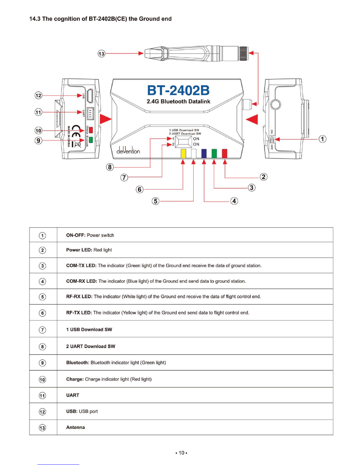
14.3 The cognition of BT-2402B(CE) the Ground end
CD
ON-OFF:
Power switch
0
Power LED: Red light
0
COM-TX LED: The indicator (Green light) of the Ground end receive the data of ground station.
0
COM-RX LED: The indicator (Blue light) of the Ground end send data to ground station.
0
RF-RX LED: The indicator (White light) of the Ground end receive the data of flight control end.
0
RF-TX LED: The indicator (Yellow light) of the Ground end send data to flight control end.
®
1 USB Download SW
0
2 UART Download SW
0
Bluetooth:
Bluetooth indicator light (Green light)
CD
Charge:
Charge indicator light (Red light)
0
UART
0
USB:
USB port
0
Antenna
•
10 •

PPM OUT r
C
PWM2 OUT r
PWM3 OUT r
PWM1 OUT r
H
1
PWM1 IN r
PWM2 IN r
PWM3 IN
0.
PPM IN
►
DATA BUS 0-1—
AU X4 10. -411—
AUX5
■
-1
0—
A U X6 11
0
'
-Lc
PIT
ROLL
Skid landing
servo
cleVenlion
BT-2402A
2.4G Bluetooth Datalink
CE
MADE IN CHINA
14.4 Connect illustration
I.
FCS-X4
Main controller
DATA PORT
-
91"1
P
DATA BUS
RX707/RX709
Receiver
•
11 •
UP02
Adapter
deVention
BT-2402A
2.4G Bluetoath DaNtlink
CE
MADE IN CHINA
PWM1 OUT P.
PWM2 OUT
►
PWM3 OUT I.
PPM OUT
I.
k°2
UPGRADE
The back of BT-2402A(CE)
frp,
UP02
Adapter
BT-2402B
2.40 Bluetooth Datallnk
BT-2402B
2.4G BluataGth Delalink
ON
ON
-
41111
1
2
1.USB Download SW
2.UART Download SW
-
3=
ON-OFF: Power switch
2.4G FIluetnoth Datelink
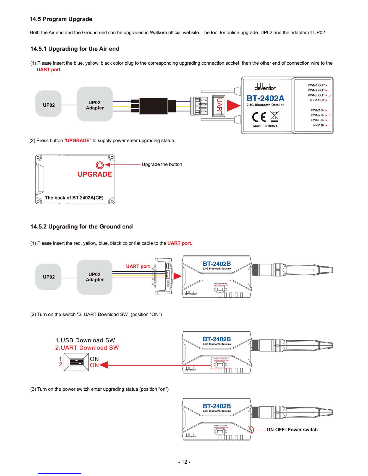
14.5 Program Upgrade
Both the Air end and the Ground end can be upgraded in Walkera official website. The tool for online upgrade: UP02 and the adaptor of UP02.
14.5.1 Upgrading for the Air end
(1) Please insert the blue, yellow, black color plug to the corresponding upgrading connection socket, then the other end of connection wire to the
UART port.
(2) Press button
"UPGRADE"
to supply power enter upgrading statue.
Upgrade the button
14.5.2 Upgrading for the Ground end
(1) Please insert the red, yellow, blue, black color flat cable to the
UART port.
(2) Turn on the switch '2. UART Download SW" (position "ON")
(3) Turn on the power switch enter upgrading status (position "on")
•
12 •

14.6 LED Indicator descriptions
LED status
Status instructions
The Air
end
The Air end and Ground end is receiving/sending dates
Green LED flashes quickly
The Air end and Ground end is not receiving/sending dates
Green LED keeps solid
The Air end and Flight control end is receiving/sending dates
Blue LED flashes quickly
The Air end and Flight control end is not receiving/
sending dates
Blue LED keeps solid
The Air end and Ground end lost signal
Green and Blue LED
flashes slowly
The
Ground
end
Normal power voltage
Onkeeps
solid of Power LED
Power voltage is less than 3.3V
Red blinks of Power LED
The Ground end is receiving Ground Station dates
Green flashes quickly of COM-TX LED
The Ground end is not receiving Ground Station dates
eirp
keeps solid of COM-TX LED
The Ground end is sending dates to Ground Station
Blue flashes quickly of COM-RX LED
The Ground end is not sending dates to Ground Station
Blue keeps solid of COM-RX LED
The Ground end is receiving Flight Control end datas
White flashes quickly of RF-RX LED
The Ground end is not receiving Flight Control end dates
1Whitel keeps solid of[RF-RX LEDI
Yellow flashes quickly of RF-TX LED
The Ground end is sending datas to Flight Control end
Yellow keeps solid of RE-TX LED
The Ground end is not sending dates to Flight Control end
The Ground end lost contact with the Air end
1Whitel and Yellow flashes slowly of RF
Bluebooth unconnnect
Green LED flashes quickly of Bluetooth
Bluebooth connnected
Green LED flashes slowly of Bluetooth
On charging
Red LED keeps solid of[i]EM
Charge finished I normal situation
Red LED out of Charge
•
13 •

Advanced
Use offline maps
use map tiles on the local storage for offline map view(under Maps directory)
Enable
Auto Pan
auto pan the map according a new GPS coordinate received
Enable Text To Speech
speak messages far important events
Enable ITS English
speak messages far important events_english
Enable
-
7S Chinese
speak messages for important ovents_chinese
Enable FollowMe
Mode
fly to Mobilephone GPS coordinate
FollowMe Height Set
default height = 10
One Key Takeoff
default height = 10
Waypoint Default Altitude
default height = 15
Flight
Path Size
512(set to zero to disable)
Channel Reverse:
ELEV
AILE
THRO
RUDD
Wifi Camera
Parameter Setting:.
Parameter Configu
BlueTooth Upgrade:
Connect/Diconnect:
UI Style:
1:23
O
0
0
O
15.0 Ground station firmware setting
15.1 Channel setting
In the main screen, touch • icon and enter setting screen as shown below:
Configuration
Channel Reverse:
ELEV
AILE
O
THRO
O
RUDD
0
Wit Camera
O
Parameter Setting:
Parameter Configurationg:
BlueTooth Upgrade:
MAW
Conneet/Diconnect:
UI Style:
ELEV, AILE, THRO, RUDD fault setting is "NORMAL".
15.2 Parameter Setting
Configuration
(1)
FollowMe Height Set
Default height=10m
You can change the height by setting the datas(5-200m).
(2)
One Key Takeoff
Default height=10m
You can change the height by setting the datas(5-15m).
(3)
Waypoint Default Altiude
Default height=15m
You can change the height by setting the datas(5-400m).
•
14 •

Configuration
Channel Reverse:
ELEV
AILE
THRO
RUDD
Wrfi Camera
Parameter Setting:
Parameter Configurationg:
we.
BlueTooth Upgrade:
NMI
Connect/Diconnect:
UI Style:
1311
162E1
Accelerometer Calibration
Press Calibrate to start
Channel Reverse:
ELEV
AILE
THRO
RUDD
Wifi Camera
Parameter Setting:
Parameter Configurationg:
STueTooth Upgrade:
Connect/Diconnect:
UI Style:
=MP
Configuration
FailSafe
Disabled
Battery Monitor
Disabled
it Batt
GPS F
s Enable
GCS Fs Enable
s Enable
A
Alarm Battery
Standard battery voltage
22.2V
Low
voltage protection 21.2V
Parameters
Calibration
Flight Mode Pids
Battery/FS
Geo Fence
Measured voltage
Calculat voltage
Voltage atio
battery voltage point Egg FS Pwm
Low battery warning 21.4V
22.2
0-00
2.592
Geo Fence
lick the box if you need to use.
Type
Altitude and circle
Action
RTL or Land
Max
Max Radius
RTL Altitude
15-1000m
Al- 15-1000m
-al- 15-80m
Parameters
Calibration
Flight Mode Pids
BatterylFS
Geo Fence
Configuration
Channel Reverse:
ELEV
RILE
THRO
RUDD
Wifi Camera
Parameter Setting:
Parameter Configurationg:
mu-
EAueTooth Upgrade:
Connect/Diconnect:
UI Style:
CO BM
15.3 Accelerometer Calibration
Parameters
Calibration
Flight Mode Pids BatterylFS
Geo Fence
Acc Calibration
Press Calibrate to start IMU
calibration. Ensure autopilot is
placed on a FLAT surface before
beginning the calibration process
Calibrate
15.4 Battery voltage point
15.5 Geo Fence
•
15 •

1
2
1.USB Download SW
2.UART Download SW
ON
-411
ON
1'0 0 0
BT-2402B
2.4G Oluatoath Oetalink
1
2
ON
ON
-411
\
/
fay
/
\
1.USB Download SW
2.UART Download SW
15.6 BlueTooth Upgrade
15.6.1 BT-2401B/BT2402B Ground end upgrading
(2) Turn on the switch "2. UART Download SW" (position "ON")
(2)
Connect the Ground end BT-2401B/BT-2402B to Ground Station software GCS and entering into the upgrade interface.
(3)
Choose the correct Ground end file to upgrade
15.6.2 BT
-
2401A/BT2402A Air end upgrading
(1) Turn on the switches of USB Download SW" and "2. UART Download SW" (To"ON")
(2)
Connect the air end BT-2401B/BT2402B to Ground station software GCS and enter into the upgrade interface
(3)
Connect both Air end BT-2401A/BT2402A and Ground end BT-2401B/2402B.
(4)
Choose the correct air end file to upgrade
Configuration
Channel Reverse.
ELEV
O
BlueTooth Upgrade
AILE
O
Firmware information
THRO
O
RUDD
O
Wifi Camera
O
Parameter Setting:1
Fite
Parameter Configu
•
IMP'
BlueTooth Upgrade:
Connect/Diconnect:
17.2 KB
UI Style:
Touch select file
Touch GO to
C213
1E20
start update
BfueTaoth Upgrade
Firmware information
File
17.2
KB
BlueTooth Upgrade Successful!
Tips:
Please
Please reconnect and upgrade again if the upgrading can't be finished and succeed in one minute.
•
16 •

AIM Effi:
IAN INDA1V0 SlikktIOD
TELEMETRY CON
U
deenlbn
AIJX2
ADXI
,
i-TagTOA
C E
XAUX8
AUX5
MADE
IN TAINT At/%T
DATA NUT
16.0 FCS-X4 Main controller guideline
©
0 24
deUenl
GE
ion
AUX 2 MA
ALIN F
AUX F-
19
P. At
2
FCS-X4
THRO
E.
IF
M
1
AR 1.
.4
M3
THROE.
Main controller
ELEN
0
K4
M
5
4
ARE IF
~
Mg10
C E
CHECK POWER F
0
.1 M7
-
MADE IN CHINA
DATA Bus
IP-
1
1
. .
1
M8
JUMP PORT IF
g
TT
0
To roundly cruise flight mode
0
To check voltage(connect with power board)
ED
Connect with fifth way brushless ESC
(9
To hyper 10C
4 ,‘
,
.
'
Y
Used for data transmission-connect the PPM OUT
port of BT-2401A/2402A
°
Connect with forth way brushless ESC
0
To one key to take off
4, \
\L-v
Jumper port, when regular receiver is
need, insert random equipped bind plug pls.
0
Connect with third way brushless ESC
0
Control Mode Switch
g
To link LED
®
Connect with second way
brushless ESC
0
To control Rudder
g
To link GPS module(red white blue black four color cable)
i:)1
Connect with first way brushless ESC
0
To control Throttle
0
Connect with eighth way brushless ESC
igi
Upgrade channel
®
To control Elevator
(forward & backward)
g
Connect with seventh way brushless ESC
0
Data communcation port
®
To control Aileron
(leftward & rightward)
0
Connect with sixth way brushless ESC
0
To link Compass
(red black double color cable)
17.0 DEVO RX7071RX709 Receiver guideling
Telemetry connector(connect with single white line)
DATA BUS: Used for data transmission-connect the PPM IN port of BT-2401A/2402A
AUX1: One key to take off(no need to connect)
Hyper IOC(no need to connect)
Roundly cruise flight mode(no need to connect)
AUX4:
Connect the servo of landing skid-connect the PWM3 IN port of BT-2401A/2402A
AUX5:
Connect gimbal Roll singal cable-connect the PWM 2 IN port of BT-2401A/2402A
AUX6:
Connect gimbal PIT singal cable-connect the PWM 1 IN port of BT-2401A/2402A
AUX7:
Connect camera controller/Clear fix ID code(When clear fix ID code is need, insert random equipped bind plug pls).
Attention: DEVO RX707(CE) and DEVO RX709(FCC)have the same ports.
•
17 •

cleUention
Tel.: (8620) 8491 5115 8491 5116
Fax.: (8620) 8491 5117
Add.: Taishi Industrial Park, Dongchong Town
nansha District, 511475 Guangzhou
Specifications,contents of parts and aysilability
are subject to change,Walkera is not responsible
for inadvert errors
in this publication.
E
•
-1/14
0
Web:www.walkera.com
USA Warehouse: iUASinc.com
Other manuals for Scout X4
3
Table of contents
Other devention Drone manuals


