DeVilbiss Air Power Company 102D User manual
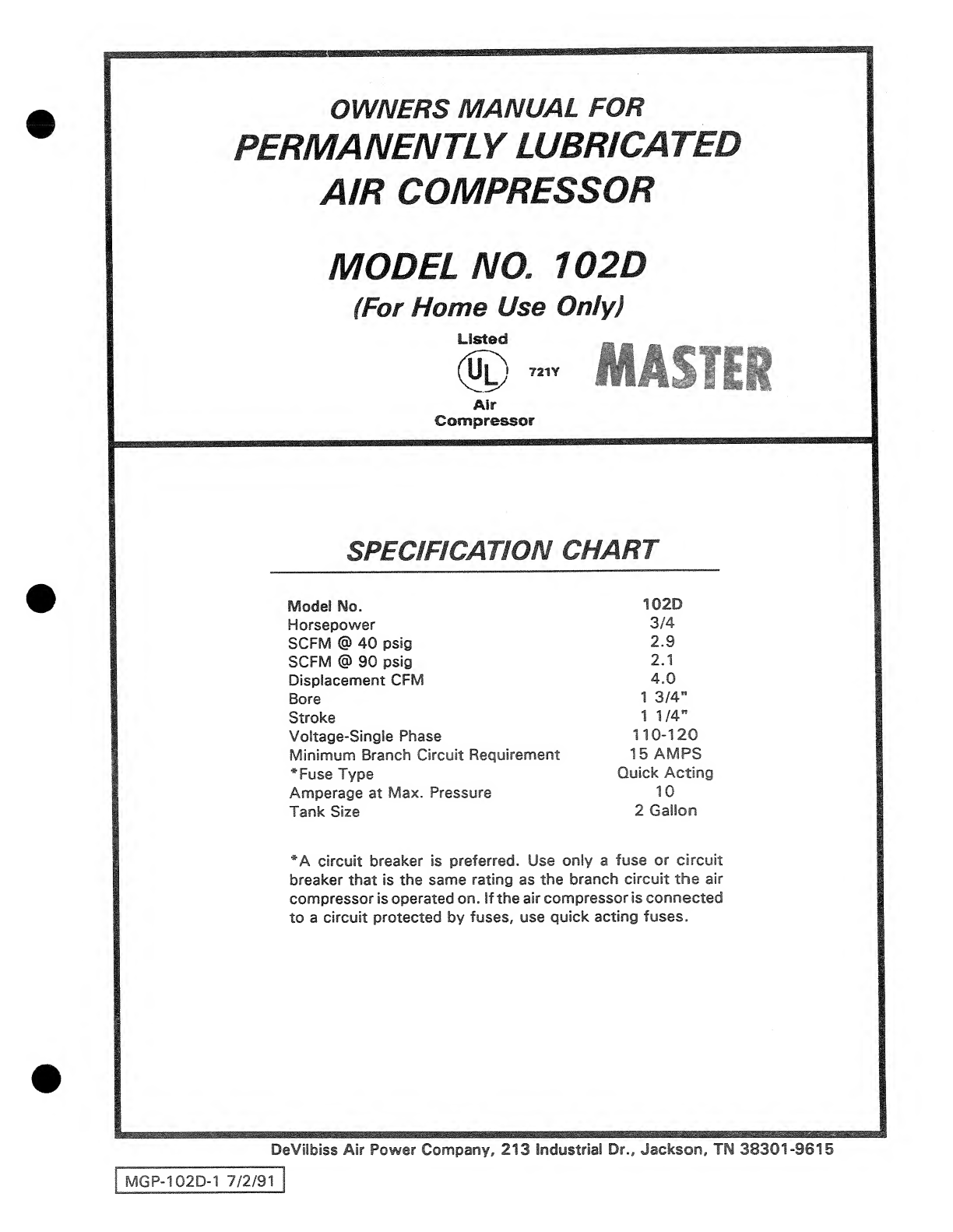
Model
No.
102D
Horsepower
3/4
SCFM
@
40
psig
2.9
SCFM
@
90
psig
2.1
Displacement
CFM
4.0
Bore
1
3/4"
Stroke
1
1/4"
Voltage-Single
Phase
110-120
Minimum
Branch
Circuit
Requirement
15
AMPS
*Fuse
Type
Quick
Acting
Amperage
at
Max.
Pressure
10
Tank
Size
2
Gallon
*A
circuit
breaker
is
preferred.
Use
only
a
fuse
or
circuit
breaker
that
is
the
same
rating
as
the
branch
circuit
the
air
compressor
is
operated
on,
if
the
air
compressor
is
connected
to
a
circuit
protected
by
fuses,
use
quick
acting
fuses.
DeVilbiss
Air
Power
Company,
213
Industrial
Dr..
Jackson.
TN
38301-9615
MGP-102D-1
7/2/91
SAFETY
GUIDELINES
Page
.
3
WARNING
CHART.
GLOSSARY
.
UNPACKING
INSTRUCTIONS.
STORAGE
.
DESCRIPTION
OF
OPERATION.
INSTALLATION
AND
BREAK-IN
PROCEDURES
..
Location
of
Air
Compressor.
Extension
Cords.
Grounding
Instructions.
Air
Hose.
OPERATING
PROCEDURES.
TROUBLESHOOTING
GUIDE
.
AIR
COMPRESSOR
DIAGRAM
&
PARTS
LIST
...
COMPRESSOR
PUMP
DIAGRAM
&
PARTS
LIST
HOW
TO
ORDER
REPAIR
PARTS.
2
LO
LO
ID
CO

mDELME*
This
manual
contains
information
that
is
important
for
you
to
know
and
understand.
This
information
relates
to
protecting
YOUR
SAFETY
and
PREVENTING
EQUIPMENT
PROBLEMS.
To
help
you
recognize
this
information,
we
use
the
following
symbols.
Please
read
the
manual
and
pay
attention
to
these
sections.
URGENT
SAFETY
INFORMATION
-
A
HAZARD
THAT
WILL
CAUSE
SERIOUS
INJURY
OR
LOSS
OF
LIFE.
IMPORTANT
SAFETY
INFORMATION
A
HAZARD
THAT
MIGHT
CAUSE
SERIOUS
INJURY
OR
LOSS
OF
LIFE.
CAUTION
Information
for
preventing
damage
to
equip¬
ment.
NOTE
Information
that
you
should
pay
special
attention
to.
HAZARDS
CAN
OCCUR
IF
EQUIPMENT
IS
NOT
USED
PROPERLY.
PLEASE
READ
THE
FOLLOWING
CHART.
WHAT
TO
LOOK
FOR
WHAT
COULD
HAPPEN
HOW
TO
PREVENT
IT
Hot
Parts
When
operated
continuously,
the
air
hose
gets
hot,
especially
near
the
compressor,
if
you
maintain
contact
by
grasping
you
may
suffer
minor
burns
or
discomfort.
Never
touch
the
air
compressor
head
during
or
immediately
after
operation.
On
tank
mounted
units,
the
plumbing
between
the
pomp
and
tank
gets
hot.
On
tank
mounted
units,
avoid
prolonged
contact
with
the
pump
to
tank
plumbing.
Flammabie
Vapors
:
It
is
normal
for
the
motor
and
pressure
switch
to
spark.
A
spark
can
ignite
flammable
vapors
from
gasoline
or
solvents,
causing
a
fire
or
explosion.
,
The
air
compressor
must
only
be
used
in
well
.
ventilated
areas,
free
of
gasoline
or
solvent
vapors.
Do
not
operate
the
compressor
while
you
are
carry¬
ing
it,
or
in
the
spray
area.
Compressed
Air
Compressed
air
can
propel
dust,
dirt
or
loose
par¬
ticles
it
comes
in
contact
with.
These
propelled
particles
may
cause
serious
injury
or
damage.
Never
point
any
nozzle
or
sprayer
toward
a
person
or
any
part
of
the
body.
Always
wear
safety
goggles
or
glasses
when
using
the
air
compressor.
Too
much
air
pressure
applied
to
air
tools
or
acces¬
sories
can
cause
damage
or
risk
of
bursting.
Always
turn
the
air
compressor
off
before
attaching
or
removing
accessories.
Check
the
manufacturer's
pressure
rating
for
air
tools
and
accessories.
Regulator
outlet
pressure
must
never
exceed
the
maximum
pressure
rating.
3

WHAT
COULD
HAPPEN
WHAT
TO
LOOK
FOR
HOW
TO
PREVENT
IT
Electricity
Your
air
compressor
is
powered
by
electricity.
Like
any
other
electrically
powered
device,
if
it
is
not
used
properly
it
may
cause
electrical
shock.
Always
unplug
the
air
compressor
prior
to
mainte-
nance
or
repair.
Never
use
the
air
compressor
in
the
rain.
Always
plug
the
cord
into
an
electrical
outlet
with
the
specified
voltage
and
adequate
fuse
protection.
Toxic
Vapors
it
is
normal
for
compressed
air
to
contain
toxic
or
irritating
vapors.
Such
vapors
are
harmful
if
inhaled.
Never
directly
inhale
the
compressed
air
produced
by
this
unit.
Certain
materials
you
are
spraying
{like
paint,
weed
killer,
sand
or
insecticide}
can
be
harmful
if
you
inhale
them.
Read
labels
and
safety
data
for
all
materials
you
spray.
Follow
all
safety
precautions.
Read
and
follow
the
safety
instructions
provided
on
the
label
or
safety
data
sheet
for
the
material
you
are
spraying.
Use
a
respirator
mask
if
there
is
a
chance
of
inhaling
anything
you
are
spraying.
Read
all
in¬
structions
...
be
sure
that
the
respirator
mask
is
suitable
for
your
application.
Unsuitable
Solvents
The
solvents
1,1,1
-
Trichloroethane
and
IVlethylene
Chloride
can
chemically
react
with
aluminum
used
in
paint
spray
guns,
paint
pumps,
etc.,
and
cause
an
explosion.
These
solvents
can
also
react
with
galvanized
components
and
cause
corrosion
and
weakening
of
parts.
This
does
not
affect
your
air
compressor
-
but
it
may
affect
the
equipment
being
used.
Read
the
label
or
data
sheet
supplied
with
the
material
you
intend
to
spray.
If
it
contains
the
solvents
listed
do
not
use
accessories
that
contain
aluminym
or
galvanized
parts.
You
must
either
change
the
material
you
intend
to
spray,
or
use
only
stainless
steel
spray
equipment.
GLOSSARY
SCFM
or
CFM:
Standard
Cubic
Feet
per
Minute;
a
unit
U.L.
Listed;
Underwriter
Laboratories;
Samples
of
of
measurement
of
air
delivery.
compressor
outfits,
taken
from
production,
were
sub¬
mitted
to
U.L.
and
found
to
comply
with
their
require-
PSIG
or
PSI:
Pounds
per
square
inch
gauge.
ments
for
design
and
performance.
;;
_
U
N
PACKING
INSTRUCTmi^S
Grasp
the
handle
and
lift
the
air
compressor
out
of
the
carton.
Remove
the
styrofoam
and/or
cardboard
and
discard.
STORAGE
When
you
have
finished
using
the
air
compressor:
1.
Set
the
"ON/OFF"
switch
to
"OFF"
and
unplug
the
cord.
2.
Relieve
all
pressure
from
the
air
compressor
head
and
air
hose
by
setting
the
adjustable
pressure
valve
to
10
P.S.I.
3.
Protect
the
electrical
cord
and
air
hose
from
dam¬
age
by
winding
them
loosely
around
the
air
com¬
pressor.
4.
Store
the
air
compressor
in
a
clean
and
dry
location.
4
DESCRIPTION
OF
OPERATION
I
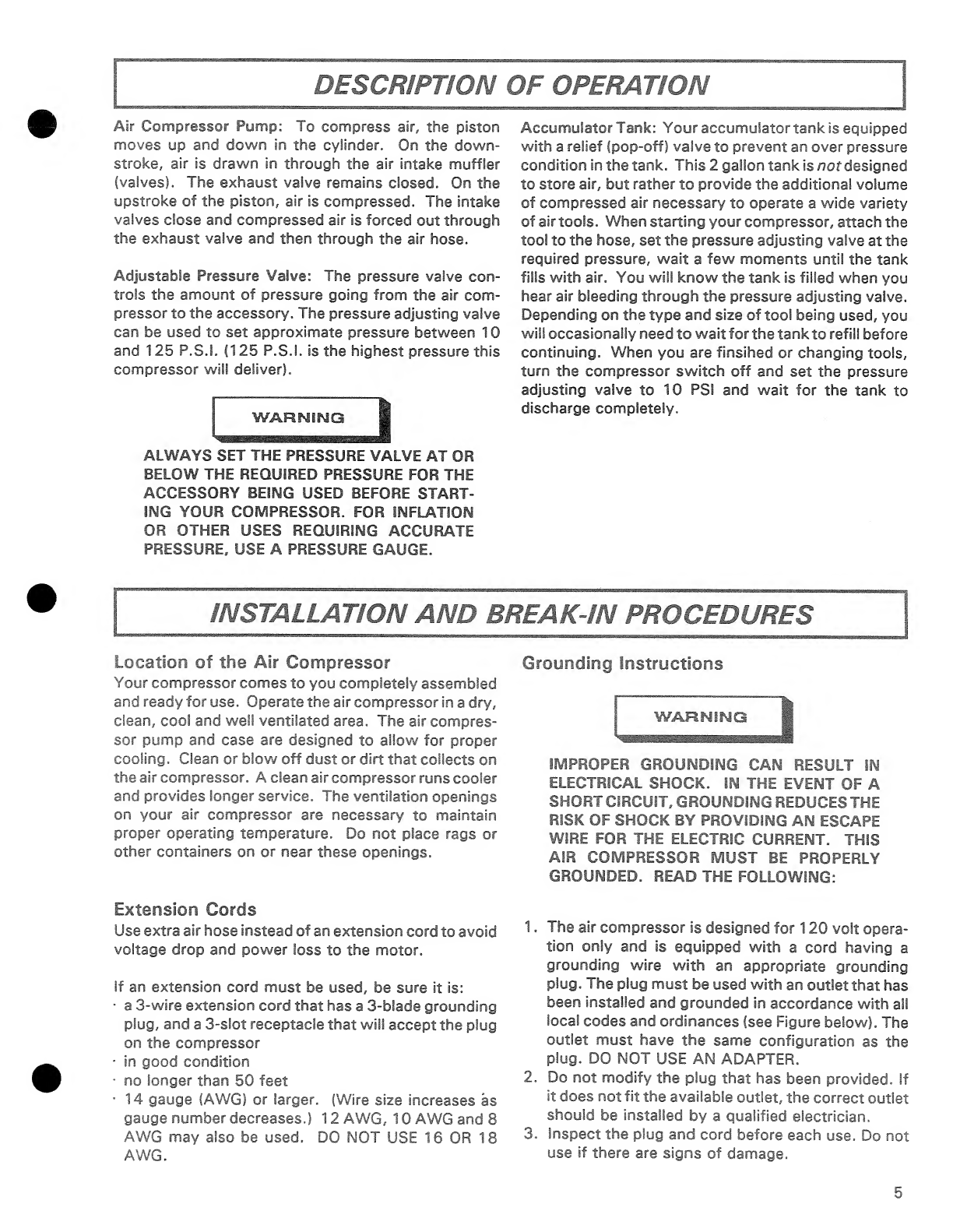
Air
Compressor
Pump:
To
compress
air,
the
piston
moves
up
and
down
in
the
cylinder.
On
the
down-
stroke,
air
is
drawn
in
through
the
air
intake
muffler
(valves).
The
exhaust
valve
remains
closed.
On
the
upstroke
of
the
piston,
air
is
compressed.
The
intake
valves
close
and
compressed
air
is
forced
out
through
the
exhaust
valve
and
then
through
the
air
hose.
Adjustable
Pressure
Valve:
The
pressure
valve
con¬
trols
the
amount
of
pressure
going
from
the
air
com¬
pressor
to
the
accessory.
The
pressure
adjusting
valve
can
be
used
to
set
approximate
pressure
between
10
and
125
P.S.I.
(125
P.S.I.
is
the
highest
pressure
this
compressor
will
deliver).
ALWAYS
SET
THE
PRESSURE
VALVE
AT
OR
BELOW
THE
REQUIRED
PRESSURE
FOR
THE
ACCESSORY
BEING
USED
BEFORE
START¬
ING
YOUR
COMPRESSOR.
FOR
INFLATION
OR
OTHER
USES
REQUIRING
ACCURATE
PRESSURE.
USE
A
PRESSURE
GAUGE.
Accumulator
Tank:
Your
accumulator
tank
is
equipped
with
a
relief
(pop-off)
valve
to
prevent
an
over
pressure
condition
in
the
tank.
This
2
gallon
tank
is
nof
designed
to
store
air,
but
rather
to
provide
the
additional
volume
of
compressed
air
necessary
to
operate
a
wide
variety
of
air
tools.
When
starting
your
compressor,
attach
the
tool
to
the
hose,
set
the
pressure
adjusting
valve
at
the
required
pressure,
wait
a
few
moments
until
the
tank
fills
with
air.
You
will
know
the
tank
is
filled
when
you
hear
air
bleeding
through
the
pressure
adjusting
valve.
Depending
on
the
type
and
size
of
tool
being
used,
you
will
occasionally
need
to
wait
for
the
tank
to
refill
before
continuing.
When
you
are
finsihed
or
changing
tools,
turn
the
compressor
switch
off
and
set
the
pressure
adjusting
valve
to
10
PSI
and
wait
for
the
tank
to
discharge
completely.
INSTALLATION
AND
BREAK-IN
PROCEDURES
Location
of
the
Air
Compressor
Your
compressor
comes
to
you
completely
assembled
and
ready
for
use.
Operate
the
air
compressor
in
a
dry,
clean,
cool
and
well
ventilated
area.
The
air
compres¬
sor
pump
and
case
are
designed
to
allow
for
proper
cooling.
Clean
or
blow
off
dust
or
dirt
that
collects
on
the
air
compressor.
A
clean
air
compressor
runs
cooler
and
provides
longer
service.
The
ventilation
openings
on
your
air
compressor
are
necessary
to
maintain
proper
operating
temperature.
Do
not
place
rags
or
other
containers
on
or
near
these
openings.
Extension
Cords
Use
extra
air
hose
instead
of
an
extension
cord
to
avoid
voltage
drop
and
power
loss
to
the
motor.
If
an
extension
cord
must
be
used,
be
sure
it
is:
•
a
3-wire
extension
cord
that
has
a
3-blade
grounding
plug,
and
a
3-slot
receptacle
that
will
accept
the
plug
on
the
compressor
•
in
good
condition
■
no
longer
than
50
feet
•
14
gauge
(AWG)
or
larger.
(Wire
size
increases
as
gauge
number
decreases.)
12
AWG,
10
AWG
and
8
AWG
may
also
be
used.
DO
NOT
USE
16
OR
18
AWG.
Grounding
Instructions
WAJ=tNiNG
IMPROPER
GROUNDING
CAN
RESULT
IN
ELECTRICAL
SHOCK.
IN
THE
EVENT
OF
A
SHORT
CIRCUIT.
GROUNDING
REDUCES
THE
RISK
OF
SHOCK
BY
PROVIDING
AN
ESCAPE
WIRE
FOR
THE
ELECTRIC
CURRENT.
THIS
AIR
COMPRESSOR
MUST
BE
PROPERLY
GROUNDED.
READ
THE
FOLLOWING:
1.
The
air
compressor
is
designed
for
120
volt
opera¬
tion
only
and
is
equipped
with
a
cord
having
a
grounding
wire
with
an
appropriate
grounding
plug.
The
plug
must
be
used
with
an
outlet
that
has
been
installed
and
grounded
in
accordance
with
ail
local
codes
and
ordinances
(see
Figure
below).
The
outlet
must
have
the
same
configuration
as
the
plug.
DO
NOT
USE
AN
ADAPTER.
2.
Do
not
modify
the
plug
that
has
been
provided.
If
it
does
not
fit
the
available
outlet,
the
correct
outlet
should
be
installed
by
a
qualified
electrician.
3.
Inspect
the
plug
and
cord
before
each
use.
Do
not
use
if
there
are
signs
of
damage.
5

Air
Hose
RISK
OF
ELECTRICAL
SHOCK.
IF
REPAIRING
OR
REPLACING
CORD
OR
PLUG,
THE
GROUNDING
WIRE
MUST
BE
KEPT
SEPA¬
RATE
FROM
THE
CURRENT-CARRYING
WIRES.
NEVER
CONNECT
THE
GROUNDING
WIRE
TO
A
FLAT
BLADE
PLUG
TERMINAL.
The
air
hose
attached
to
your
comporessor
has
an
integral
pressure
adjusting
valve
at
the
working
end
of
the
hose.
Should
service
or
replacement
be
required,
make
sure
that
the
pressure
adjusting
valve
is
present
in
the
air
hose
line.
If
these
grounding
instructions
are
not
completely
understood,
or
if
in
doubt
as
to
whether
the
compres¬
sor
is
properly
grounded,
have
the
installation
checked
DO
NOT
REPLACE
THE
HOSE
WITH
STAN¬
DARD
HOSE
THAT
IS
NOT
EQUIPPED
WITH
THE
PRESSURE
ADJUSTING
VALVE.
Do
not
allow
hose
to
become
kinked
or
pinched
at
any
time.
This
is
important
to
avoid
damage
to
your
compressor
and
to
maintain
pressure
1.
Before
plugging
in
the
air
compressor,
set
the
adjustable
pressure
valve
to
"10"
PSI.
Make
sure
the
"ON/OFF"
switch
is
in
the
"OFF"
position.
2.
Connect
the
air
tool
or
accessory
to
the
air
hose.
Tighten
securely.
3.
Plug
the
power
cord
into
the
grounded
outlet.
4.
Start
the
compressor
by
setting
the
"ON/OFF"
switch
to
the
"ON"
position.
5.
Check
the
manufacturer's
maximum
pressure
rat¬
ing
for
the
air
tool,
accessory
or
vehicle
tire
being
used.
The
air
compressor
outlet
pressure
must
never
exceed
the
maximum
pressure
rating.
6.
Slowly
increase
the
pressure
setting
of
the
adjust¬
able
pressure
valve.
You
should
be
able
to
hear
and
feel
air
pressure
being
relieved
by
the
adjustable
pressure
valve.
If
pressure
is
not
being
relieved,
turn
the
air
compressor
off
immediately.
The
pressure
valve
must
be
replaced.
TOO
MUCH
AIR
PRESSURE
COULD
CAUSE
AN
AIR
TOOL
OR
VEHICLE
TIRE
TO
RUPTURE
OR
EXPLODE.
CAREFULLY
FOLLOW
STEPS
5
AND
6
EACH
TIME
YOU
USE
YOUR
COMPRESSOR.
CAUTION
Compressed
air
from
the
outfit
may
contain
water
condensation.
Do
not
spray
unfiltered
air
at
an
item
that
could
be
damaged.
Some
air
operated
tools
or
devices
may
require
filtered
air.
Read
the
instructions
for
the
air
tool
or
device.
6

WARNING
VOLTAGE
SOURCES,
MOVING
PARTS
OR
COMPRESSED
AIR
SOURCES
ARE
EXPOSED
WHEN
REPAIRING
THE
COMPRESSOR.
PERSONAL
INJURY
CAN
OCCUR.
UNPLUG
THE
COMPRESSOR
BEFORE
ATTEMPTING
ANY
REPAIRS.
PROBLEM
CAUSE
Air
Leaks
Hose
fitting
loose.
Tighten
fitting.
Compressor
is
not
deliver¬
ing
enough
air.
Prolonged
excessive
use
of
air.
Decrease
the
amount
of
air
usage.
Your
compressor
is
not
large
enough
for
the
air
requirement.
Hole
in
hose.
Replace
the
hose.
Air
leaks.
Tighten
fittings.
Motor
will
not
run.
Fuse
blown,
circuit
breaker
tripped.
1.
Check
fuse
box
for
blown
fuse
and
replace
as
necesssary.
Reset
circuit
breaker.
Do
not
use
a
fuse
or
circuit
breaker
with
higher
rating
than
that
specified
for
your
particu¬
lar
branch
circuit.
2.
Check
for
proper
fuse.
You
should
be
using
a
Quick
Acting
fuse.
3.
Check
for
low
voltage
problem.
4.
Check
the
extension
cord.
5.
Disconnect
the
other
electrical
appliances
from
circuit
or
operate
the
compressor
on
its
own
branch
circuit.
Extension
cord
is
wrong
length
or
gauge.
Check
the
extension
cord.
Loose
electrical
connections.
Check
wiring
connection
inside
terminal
box
Faulty
motor.
Have
checked
at
a
local
Service
Center.
High
discharge
pressure.
Cannot
be
adjusted
lower.
Adjustable
pressure
valve
not
functioning.
I----
■
■
1
WARNING
1
RISK
OF
BURSTING.
DO
NOT
OPER¬
ATE
THE
COMPRESSOR
IF
THIS
PROB¬
LEM
EXISTS.
ADJUSTABLE
PRESSURE
VALVE
MUST
BE
REPLACED.
7
ir
compressor
oiagram
L.
^
5
6
i
TO
TANK
9
‘POWER
CORD
(GREEN)
GROUND
WIRE
\
■
<
wA
y6r\
^
I
I
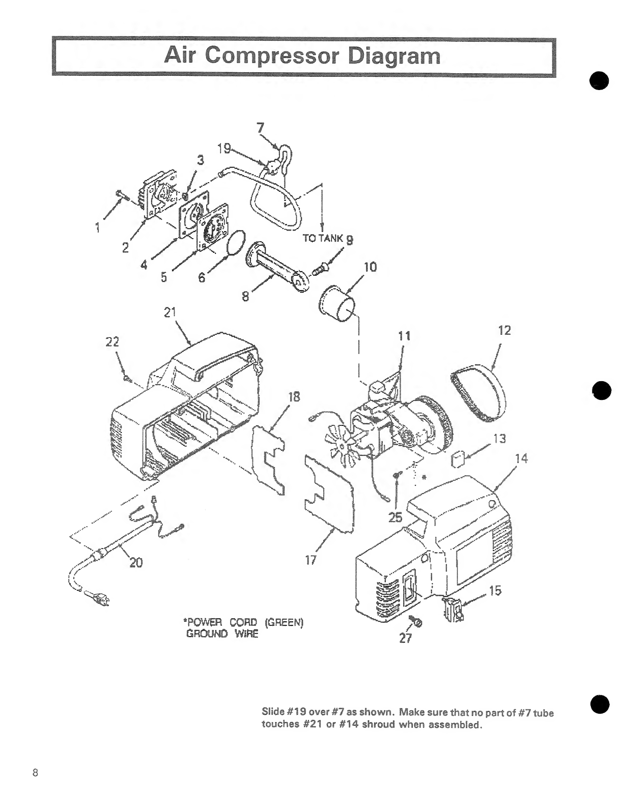
Slide
#19
over
#7
as
shown.
Make
sure
that
no
part
of
#7
tube
touches
#21
or
#14
shroud
when
assembled.
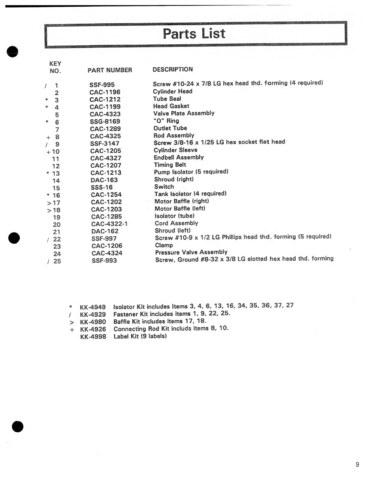
KEY
NO.
PART
NUMBER
DESCRIPTION
/
1
SSF-995
Screw
#10-24
x
7/8
LG
hex
head
thd.
forming
(4
required)
2
CAC-1196
Cylinder
Head
*
3
CAC-1212
Tube
Seal
*
4
CAC-1199
Head
Gasket
5
CAC-4323
Valve
Plate
Assembly
*
6
SSG-8169
”0"
Ring
7
CAC-1289
Outlet
Tube
+
8
CAC-4325
Rod
Assembly
/
9
SSF-3147
Screw
3/8-16
x
1/25
LG
hex
socket
flat
head
+
10
CAC-1205
Cylinder
Sleeve
11
CAC-4327
Endbell
Assembly
12
CAC-1207
Timing
Belt
*
13
CAC-1213
Pump
Isolator
(5
required)
14
DAC-163
Shroud
(right)
15
SSS-16
Switch
*
16
CAC-1254
Tank
Isolator
(4
required)
>17
CAC-1202
Motor
Baffle
(right)
>18
CAC-1203
Motor
Baffle
(left)
19
CAC-1285
Isolator
(tube)
20
CAC-4322-1
Cord
Assembly
21
DAC-162
Shroud
(left)
/
22
SSF-997
Screw
#10-9
x
1/2
LG
Phillips
head
thd.
forming
(5
required)
23
CAC-1206
Clamp
24
CAC-4324
Pressure
Valve
Assembly
/
25
SSF-993
Screw,
Ground
#8-32
x
3/8
LG
slotted
hex
head
thd.
forming
*
KK-4949
Isolator
Kit
includes
Items
3.
4,
6,
13,
16,
34,
35,
36,
37,
27
/
KK-4929
Fastener
Kit
includes
items
1,
9,
22,
25.
>
KK-4980
Baffle
Kit
includes
items
17,
18.
+
KK-4926
Connecting
Rod
Kit
include
items
8,
10.
KK-4998
Label
Kit
(9
labels)


Hose
Connection
Nipple
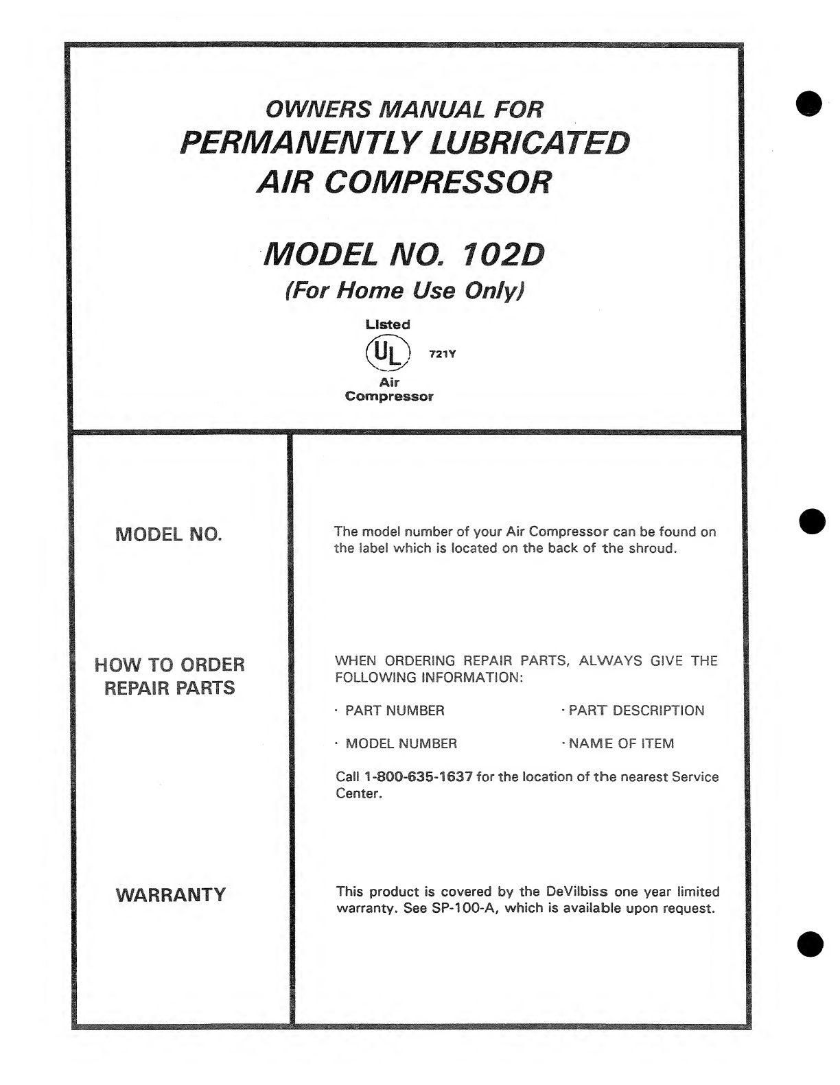
The
model
number
of
your
Air
Compressor
can
be
found
on
the
label
which
is
located
on
the
back
of
the
shroud.
WHEN
ORDERING
REPAIR
PARTS,
ALWAYS
GIVE
THE
FOLLOWING
INFORMATION;
•
PART
NUMBER
•
PART
DESCRIPTION
•
MODEL
NUMBER
■
NAME
OF
ITEM
Call
1-800-635-1637
for
the
location
of
the
nearest
Service
Center.
This
product
is
covered
by
the
DeVilbiss
one
year
limited
warranty.
See
SP-100-A,
which
is
available
upon
request.
Table of contents
Other DeVilbiss Air Power Company Air Compressor manuals

DeVilbiss Air Power Company
DeVilbiss Air Power Company Ex-Cell E7540 User manual

DeVilbiss Air Power Company
DeVilbiss Air Power Company D23757 User manual

DeVilbiss Air Power Company
DeVilbiss Air Power Company FAC1025 User manual

DeVilbiss Air Power Company
DeVilbiss Air Power Company IRC5E60VAD-1 Configuration guide
Popular Air Compressor manuals by other brands


CEVIK PRO
CEVIK PRO Pro24xt manual

Oshkosh Corporation
Oshkosh Corporation IMT CAS40P Installation, Operation, Maintenance & Parts Manual

Black & Decker
Black & Decker Start-It 90550871 instruction manual

Scheppach
Scheppach HC26 Translation of original instruction manual

Mea
Mea SMARTPACK 100-H Owner's/operator's manual

EUFAB
EUFAB 21076 manual


