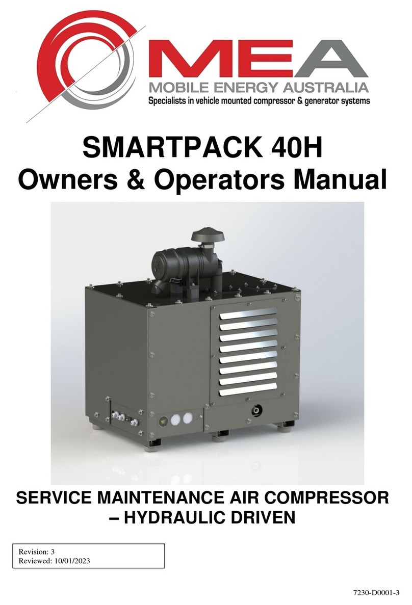
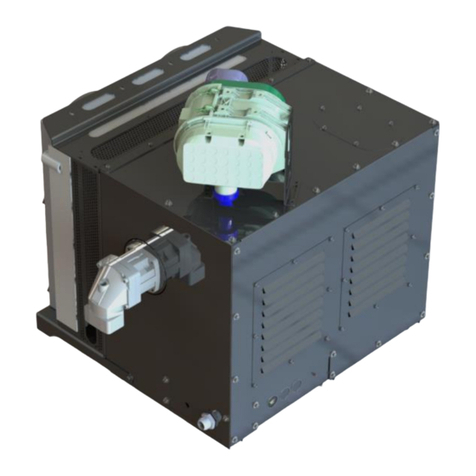
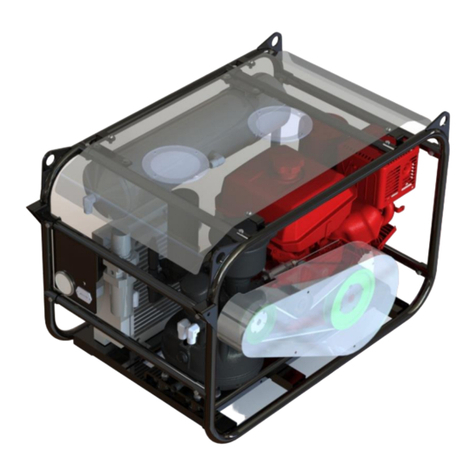
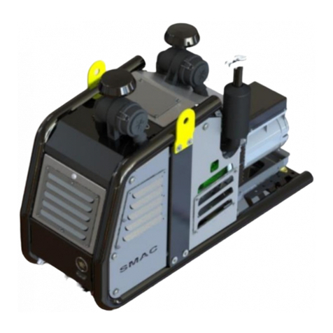
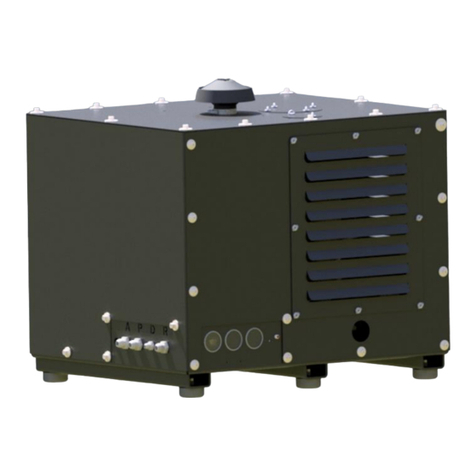
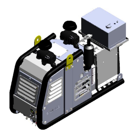
Mea SMARTPACK 100-H Owner's manual

7231-D0001-02
SMARTPACK 100-H
FRAMED MURPHY /
ELECTRONIC REMOTE BOX
Owner & Operator Manual
Revision: 3
Reviewed: 17/01/2023

Document No 7231-D0001-03
Mobile Energy Australia Pty Ltd 39 Dulacca Street, Acacia Ridge QLD 4110 Australia ABN 98 674 578 946
P: +61 7 3273 6803 E: sales@mobilenergyaustralia.com.au www.mobileenergyaustralia.com.au
MEA Product Registration Form
THE ATTACHED FORM MUST BE COMPLETED
AND
RETURNED WITHIN 30 DAYS OF INSTALLATION
OR
WARRANTY WILL BE VOID
ALTERNATIVELY, PLEASE GO ONLINE AND
COMPLETE WARRANTY FORM
www.mobileenergyaustralia.com.au/warranty-registration

Document No 7231-D0001-03
Mobile Energy Australia Pty Ltd 39 Dulacca Street, Acacia Ridge QLD 4110 Australia ABN 98 674 578 946
P: +61 7 3273 6803 E: sales@mobilenergyaustralia.com.au www.mobileenergyaustralia.com.au
MEA Product Warranty Registration Form
This form must be completed and returned to MEA at the time of
Installation. Warranty will be void if this form is not received by MEA
within 30 days of installation.
MEA Dealer Information
Company Name: _____________________________________________________________
City: _______________ State: ___________________ Country: ___________________
MEA Installer Information
Company Name: ______________________________________________________________
City: _______________ State: ___________________ Country: ___________________
Installation Date: _______ / ________ / ______
Day Month Year
Owner Information
Company Name: ______________________________________________________________
Address: _____________________________________________________________________
City: _______________ State: ___________________ Country: ___________________
Postcode: _________________________ Phone #: ________________________________
Product Information
MEA Serial Number: __________________________________________________________
Model Number: _______________________________________________________________
CUT HERE

Document No 7231-D0001-03
Mobile Energy Australia Pty Ltd 39 Dulacca Street, Acacia Ridge QLD 4110 Australia ABN 98 674 578 946
P: +61 7 3273 6803 E: sales@mobilenergyaustralia.com.au www.mobileenergyaustralia.com.au
TABLE OF CONTENTS
1. COMPRESSOR / COMPRESSED AIR SAFETY......................................................2
2. SPECIFICATIONS....................................................................................................6
3. OPERATING PROCEDURE.....................................................................................7
4. INSTALLATION........................................................................................................8
5. SCHEDULE MAINTENANCE...................................................................................9
6. SPARE PARTS.......................................................................................................10
7. TROUBLESHOOTING............................................................................................13
8. DRAWINGS & ILLUSTRATIONS...........................................................................14
9. WARRANTY ...........................................................................................................22
10. MOBILE ENERGY AUSTRALIA - CONTACTS....................................................24
11. APPENDIX A –DESIGN REGISTRATION...........................................................25
12. APPENDIX B –FLUIDS & MATERIAL SAFETY DATA SHEETS.......................26
MEA Product Warranty Registration form and partner Product Warranty Registrations
must be completed and returned to MEA.

Document No 7231-D0001-03
Mobile Energy Australia Pty Ltd 39 Dulacca Street, Acacia Ridge QLD 4110 Australia ABN 98 674 578 946
P: +61 7 3273 6803 E: sales@mobilenergyaustralia.com.au www.mobileenergyaustralia.com.au
1. COMPRESSOR / COMPRESSED AIR SAFETY
MEA DISCLAIMS ALL LIABILITIES FOR DAMAGE OR LOSS OF EQUIPMENT AND PROPERTY,
PERSONAL INJURIES (INCLUDING DEATH), AND CONSEQUENTIAL DAMAGES ARISING OUT OF
ANY MEA SYSTEM NOT USED IN ACCORDANCE WITH THE OPERATOR’S MANUAL.
ALL UNITS ARE SHIPPED WITH A DETAILED OPERATOR’S MANUAL. THIS MANUAL CONTAINS
VITAL INFORMATION FOR THE SAFE USE AND EFFICIENT OPERATION OF THE UNIT. READ THE
OPERATOR’S MANUAL BEFORE STARTING THE UNIT. FAILURE TO ADHERE TO THE
INSTRUCTIONS COULD RESULT IN SERIOUS BODILY HARM OR PROPERTY DAMAGE.
Care is required when working with an air compressor or compressed air. Compressed air is one of the many
ways energy can be stored. Releasing the stored energy in an uncontrolled manner can result in catastrophic
consequences. Death and permanent disability are possibilities that can occur due to misuse. The following
are suggested as minimum precautions to be used when operating the SMARTPACK Air Compressor. It is
important that each work site shall perform a risk analysis and produce a procedure to eliminate or control
the hazardous condition to minimise the risk to personnel and equipment. Health and Safety Regulations
necessitate that this is a compulsory process to be carried out on each site. These, together with site specific
safety procedures will help to minimize the risk to accidents, personnel injury, and loss of life. It is the
responsibility of the employer to ensure that the work site is safe for all employees and that the safety
procedures are followed by all employees.
SAFETY WHEN OPERATING AN AIR COMPRESSOR
•Do not bypass or disable the oil temperature and pressure sensors –unless planning on running to
failure (MEA does not recommend the practice).
•Do not expose the tank or compressor to extreme heat.
•Do not perform any service or repairs until the system has been completely relieved of air pressure.
•Maintenance and repairs on the system should only be done by qualified personnel.
•Do not operate the compressor while driving (vehicle mounted systems).
•Do not tamper with the pressure relief valve.
•Follow safe work practice, wear the appropriate personal protective equipment (PPE) when operating
air-powered equipment, particularly eye and hearing protection.
•Avoid contact with rotating components, ensure all safety guards are in place.
•Avoid all contact with pressurized air. If it penetrates the skin, it can enter blood stream and cause
death.
•Vaporized oil propelled by high pressure is an explosive mixture. To prevent compressor explosion
or fire, make sure that the air entering the compressor is free of flammable vapours.
•Do not breathe the compressor air, vaporized oil is a respiratory hazard.
•Stay clear of all moving parts when the system is operating.
•Follow safety procedures for service operations as set by the authority.
•Run the system at idle speed and under no load conditions for 2 to 3 minutes before turning the
system off to allow system cooling and lubrication to occur.

Document No 7231-D0001-03
Mobile Energy Australia Pty Ltd 39 Dulacca Street, Acacia Ridge QLD 4110 Australia ABN 98 674 578 946
P: +61 7 3273 6803 E: sales@mobilenergyaustralia.com.au www.mobileenergyaustralia.com.au
HYDRAULIC SAFETY
ALL HYDRAULIC EQUIPMENT MUST BE TREATED WITH EXTREME
RESPECT AND CARE. AS THE WORKING FLUID IS UNDER EXTREME
PRESSURE, UP TO 5000PSI, WITH HIGH FLOW RATES GENERATING
HIGH HEAT, ALL APPROPRIATE SAFETY PRECAUTIONS MUST BE
TAKEN IN TO ACCOUNT AND SAFETY EQUIPMENT MUST BE WORN IF
IN CONTACT WITH THE EQUIPMENT UNDER OPERATION. ALL LEAKS,
NO MATTER HOW MINOR, MUST BE RECTIFIED IMMEDIATELY AND
ANY WEAR IN THE HOSES MUST BE ADDRESSED AND EQUIPMENT
REPLACED. HYDRAULIC INJECTION IS DANGEROUS AND LIFE
THREATENING AND EVEN A PINHOLE LEAK WILL BLANKET AN ENTIRE
ENCLOSED SPACE VERY QUICKLY WITH HAZARDOUS VAPORISED
HYDRAULIC OIL MIST.

Document No 7231-D0001-03
Mobile Energy Australia Pty Ltd 39 Dulacca Street, Acacia Ridge QLD 4110 Australia ABN 98 674 578 946
P: +61 7 3273 6803 E: sales@mobilenergyaustralia.com.au www.mobileenergyaustralia.com.au
2. SPECIFICATIONS
Compressor Model: Packsmart V90
Compressor Type: Oil flooded rotary screw compressor
Hydraulic Motor Type: 32cc Gear Motor
Control: 24V/12V Electronic Control
Maximum Air Delivery: 100cfm @ 150psi
Oil Flow Requirements: 80 LPM
Oil Pressure (Nominal): 195 Bar
Drive coupling speed: 2500 rpm
Pressure Regulation: Mechanical Inlet control valve modulates flow in response to demand
Safety Features: 200 PSI relief valve in compressor sump
Temperature safety sensor in compressor
Rapid blow-down valve to discharge system pressure on shutdown
Lubrication: MEA Certified and Approved Synthetic Oil

Document No 7231-D0001-03
Mobile Energy Australia Pty Ltd 39 Dulacca Street, Acacia Ridge QLD 4110 Australia ABN 98 674 578 946
P: +61 7 3273 6803 E: sales@mobilenergyaustralia.com.au www.mobileenergyaustralia.com.au
3. OPERATING PROCEDURE
CAREFULLY READ THE OPERATING INSTRUCTIONS BELOW. FAILURE
TO ADHERE TO THE FOLLOWING COMPRESSOR OPERATING
INSTRUCTION COULD RESULT IN SERIOUS INJURY.
1. Check Oil Level
2. Check Hoses and fittings for leaks. Make sure the hoses are not loosened or damaged.
3. Check and make sure hydraulic supply/return (drain if applicable) are installed correctly.
4. Check Air Filter for Blockage.
5. Check the Safety circuit switch operation (Reset Switch).
6. Switch on the vehicle and activate the vehicle flow control (turn PTO on).
7. Turn on the compressor either at the control box or in the cab and ensure it is in the unloaded state
(check load/unload switch).
8. Turn on the unload/load switch to load and see if the compressor builds pressure to the regulated
setting.
9. Plug an air tool into the air outlet and operate. Ensure that the compressor works as required.
10. When the work is finished, switch the compressor to unload.
11. It is good practice to allow the compressor to run under no load for 2-3 minutes.
12. Switch off at either the control box or in the Cab and switch off the vehicle.
13. It is good practice to check for any visible signs of hydraulic fluid leakage and or compressor fluid
leakage after each use.
WARNING

Document No 7231-D0001-03
Mobile Energy Australia Pty Ltd 39 Dulacca Street, Acacia Ridge QLD 4110 Australia ABN 98 674 578 946
P: +61 7 3273 6803 E: sales@mobilenergyaustralia.com.au www.mobileenergyaustralia.com.au
4. INSTALLATION
The SMARTPACK 100H is designed as an integrated compressor system for connection to an existing hydraulic
system. The SMARTPACK 100H only requires connection of a pressure line in, a return line out and a
connection of the motor drain line (if applicable) to the tank.
WARNING(!) When setting the compressor unit up, ensure there is a safety mechanism in place to
prevent any excessive flow or pressure into the compressor hydraulic circuit. MEA will not warrant
any damage caused and will void warranty due to inadequate safety protection of the existing
hydraulic system.
1. Install SMARTPACK 100H into position on the vehicle using 4 x min. M12 x 1.75 Grade 8.8 Fasteners.
2. Install the hydraulic lines (i.e., pressure in, return out and drain line if applicable). The pressure line
(hydraulic oil inlet) goes to the fitting with label “P”. The return line (hydraulic oil out) goes to the fitting
with label “T”.
3. Connect the electrical harness as per the circuit diagram relevant to your vehicle.
4. Check the oil level in the compressor.
5. Switch on the vehicle, turn on the compressor at the control box and test the hydraulic solenoid for
operation.
6. Turn the unload/load switch to load and check the compressor builds pressure to the regulated
pressure setting.
7. Plug an air tool into the air outlet and operate checking that the compressor works as required, run for
10mins. Stop using air, let the compressor reach full pressure, then leave the vehicle idling for 2 to 3
minutes before switching off.
8. Switch off the vehicle and check for any visible signs of hydraulic fluid leakage.
9. When the compressor has cooled down (safe to touch), re-check the compressor oil level.
ENSURE THAT A WATER SEPARATOR IS MOUNTED AS FAR FROM THE COMPRESSOR
AS POSSIBLE OR THAT IT HAS AT LEAST TWO METRES OF HOSING BETWEEN THE
COMPRESSOR DISCHARGE AND SEPARATOR INLET.

Document No 7231-D0001-03
Mobile Energy Australia Pty Ltd 39 Dulacca Street, Acacia Ridge QLD 4110 Australia ABN 98 674 578 946
P: +61 7 3273 6803 E: sales@mobilenergyaustralia.com.au www.mobileenergyaustralia.com.au
5. SCHEDULE MAINTENANCE
The maintenance intervals recommended are based on standard operating conditions. The
intervals for inspection, lubrication and maintenance given herein are maximum intervals and
it should be noted to schedule the maintenance accordingly to sites.
When the unit is being operated in a dusty environment, in high ambient temperatures or in
other unusual conditions, an assessment needs to be done for shorter service interval.
A planned program of periodic inspection and maintenance will help to avoid premature
failure and costly repairs. Daily visual inspections should become routine.
IMPORTANT: PLEASE CONTACT MOBILE ENERGY AUSTRALIA FOR MORE INFORMATION IF YOU
HAVE ANY QUESTIONS REGARDING THE SETUP AND OPERATION OF PRODUCTS.
Interval
Compressor
ACTION TO BE TAKEN
Periodically During Operation
Observe all gauge readings. Note any change from the
normal readings and determine the cause. Have the
necessary repairs made.
(Note: “Normal” is the usual gauge reading when operating
at similar conditions on a day-to-day basis.)
Periodically or as required
Inspect and replace spin-on coalescing element if necessary.
Inspect and clean oil cooler fins.
Check system for oil and/or air leaks.
Every 10 Hours or Daily
Check the compressor oil level.
Check air filter/s and connecting hose and clamps.
Check for oil and air system, including hoses, for leaks.
Every 25 Hours or Monthly
Drain water from tank and check Compressor oil level.
After first 50 hours of operation
Check system for oil and/or air leaks.
Check engine/compressor mounts fastener torque.
Check belt and pulleys for signs of wear - note that belt
normally gives off blue particles until it runs in.
Every 100 Hours
Check compressor oil level.
Clean air cleaner element.
Check engine/compressor/generator mounts for excessive
wear and fastener torque.
Every 400 Hours of operation or 9
months (See Service Kit List)
Change compressor oil approx. 7L.
Change compressor oil filter.
Change compressor air filter.
Check belt and pulleys for signs of wear.
Check valve clearance.
800 Hours / 18 months
Change compressor coalescing filter.

Document No 7231-D0001-03
Mobile Energy Australia Pty Ltd 39 Dulacca Street, Acacia Ridge QLD 4110 Australia ABN 98 674 578 946
P: +61 7 3273 6803 E: sales@mobilenergyaustralia.com.au www.mobileenergyaustralia.com.au
7231-KB0001 SERVICE KIT –400 HOURS
7231-KB0002 SERVICE KIT –800 HOURS
SERVICE KIT BREAKDOWN
10008-P0024 AIR FILTER
10008-P0023 SPIN-ON COALESCING FILTER
10008-P0053 OIL FILTER
10019-K0005 COMPRESSOR OIL 5L (INCL. CONTAINER)
ADDITIONAL CRITICAL PARTS
10004-P0055 COUPLING TO SUITV90G/V76G
10012-P0083 UNLOADER VALVE –12V
10012-P0084 UNLOADER VALVE –24V
10015-P0002 GAUGE PRESSURE SWITCHED 2” 0-200PSI
10015-P0003 GAUGE TEMPERATURE SWITCHED 2” 4FT CAPILLARY
10015-P0005 GAUGE HOUR METER 2”
*Contact MEA spare parts sale for information regarding items (such as motor seal and
coupling) not covered herein.

Document No 7231-D0001-03
Mobile Energy Australia Pty Ltd 39 Dulacca Street, Acacia Ridge QLD 4110 Australia ABN 98 674 578 946
P: +61 7 3273 6803 E: sales@mobilenergyaustralia.com.au www.mobileenergyaustralia.com.au
7. TROUBLESHOOTING
SYMPTOMS
PROBABLE CAUSE
CORRECTIVE ACTION
The compressor does not
load.
1-The intake valve remains closed.
1-Check the valve. If necessary, replace the
damaged parts with the spare parts kit.
2-The solenoid valve does not work
accurately
2-Check the solenoid valve. If necessary,
replace it.
3-Losses on the pressure line.
3-Check pipes and cables. If necessary,
replace them.
During idling phase, the
compressor does not
discharge pressure from
separator tank
1-The solenoid valve does not work
accurately.
1-Check the solenoid valve. If necessary,
replace it.
2-The calibrated nozzle is clogged.
2-Remove the calibrated nozzle. Clean or
replace it.
Compressor capacity or
pressure lower than
usual
standard.
1-The air filter is clogged.
1-Remove the air filter. Clean or replace it.
2-The intake valve does not open.
2-Check the valve. If necessary, replace the
damaged parts with the spare parts kit.
3-Air loss from safety valve.
3-Replace the valve.
Compressor keeps on
loading over working
pressure: safety valve
opens
1-The solenoid valve does not work
accurately.
1-Check the solenoid valve. If necessary,
replace it.
2-Clogged separator filter.
2-Replace the separator filter.
Compressor overheating.
1-Insufficient cooling.
1-Check the cooling system. Check coolant
level on tank.
2-Dirty oil
2-Replace it with new oil.
3-Oil level is too low.
3-Check coolant level on tank and if
necessary, add oil.
4-Clogged-up cooler or pipe
connection
4-Clean cooler and pipes.
5-The thermostatic valve does not
work correctly.
5-Check the thermostatic valve. If necessary,
replace the damaged parts with K17 spare
parts kit (Contact MEA for parts required)
6-Clogged oil filter
6-Replaced oil filter
During unloading phase,
pressure increases up to
safety
valve opening
1-The intake valve remains open.
1-Check the valve. If necessary, replace the
damaged parts with spare parts kit.
2-The calibrated nozzle is clogged.
2-Remove the calibrated nozzle. Clean or
replace it.
Oil leakage from intake
valve only when the
machine is switched off:
oil soaked-up air filter
1-The intake valve does not work
properly
(does not close)
1-Check the valve. If necessary, replace the
damaged parts with K9 spare parts kit.
2-The no-return valve of intake valve
does not work
correctly.
2-Check it and clean it.
Oil soaked-up air filter
during
unloading phase
1-Too high level of oil in the tank
1-Check oil level on separator tank.
2- Clogged separator filter
2- Replace the separator filter.
3-The recovery oil viewer is dirty or
does not work
appropriately.
3 -Clean it or if necessary, replace the
damaged parts with K15 spare parts kit.
If separator filter is clogged up, replace it.
The compressor remains
under loading phase.
1-The intake valve does not work
properly
(does not close)
1-Check the valve. If necessary, replace the
damaged parts with spare parts kit.
Rotor seizure
1-Unknown particles inside.
1-Call MEA technical support.
2-Insufficient lubrication.
2-Call MEA technical support.
Presence of oil in the
outlet of minimum
pressure valve
1-Separator filter damaged.
1-Replace the separator filter.
2-Oil recovery viewer obstructed.
2-Clean the oil recovery viewer.
3-Separator nipple with O-rings
damaged.
3-Replace K1 spare parts kit.
Table of contents
Other Mea Air Compressor manuals

Mea
Mea SMARTPACK 180-H Owner's manual

Mea
Mea SMARTPACK 40H Owner's manual

Mea
Mea SMAC 35DG Owner's manual

Mea
Mea SMAC35D-G 15HP Owner's manual
Mea
Mea SMAC 40D-15HP Owner's manual

Mea
Mea SMARTPACK 40H Owner's manual

Mea
Mea SMARTPACK 180-H Owner's manual
Mea
Mea SMAC 35DG Owner's manual

Mea
Mea SMAC 35DWG 22HP Owner's manual
Mea
Mea SMARTPACK 75-H Owner's manual