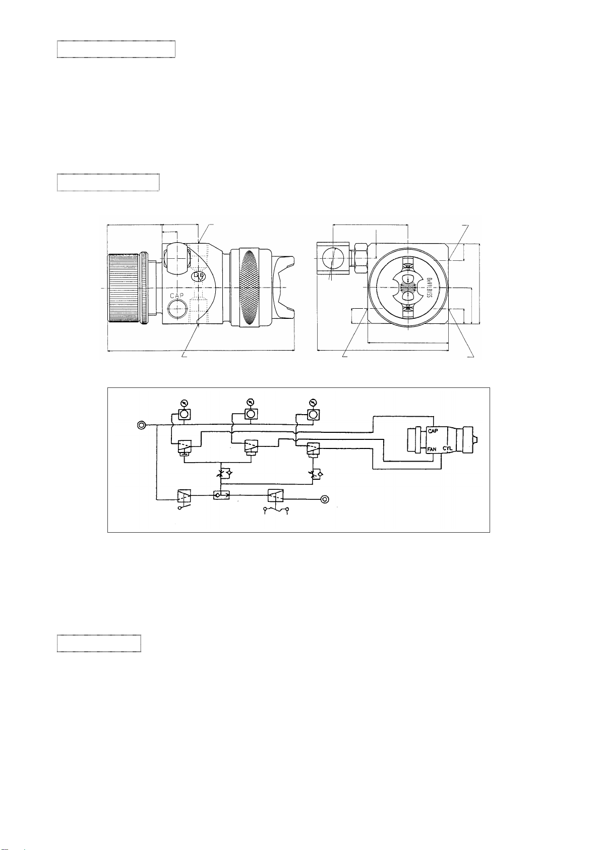
T-AGB-862/872/873/874/879/882
1301A
T-AGB(1/2)
Part Number Description Qty Remarks
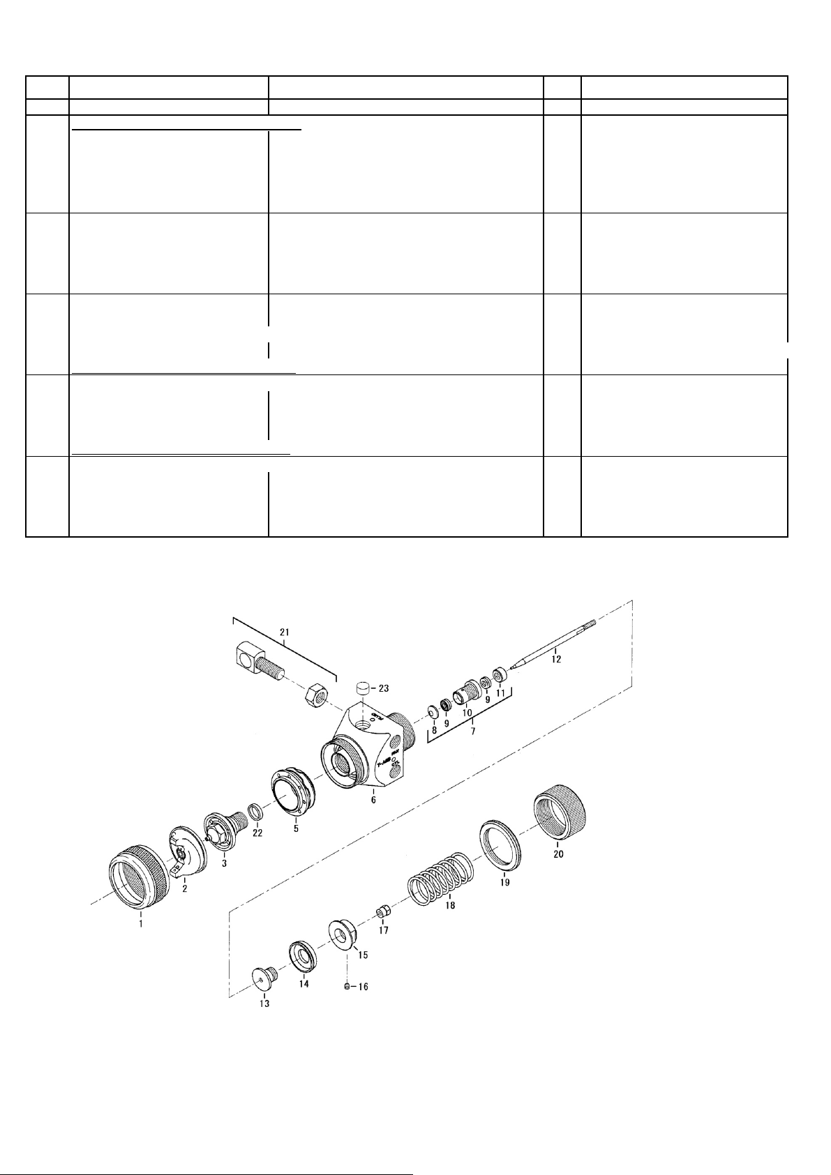
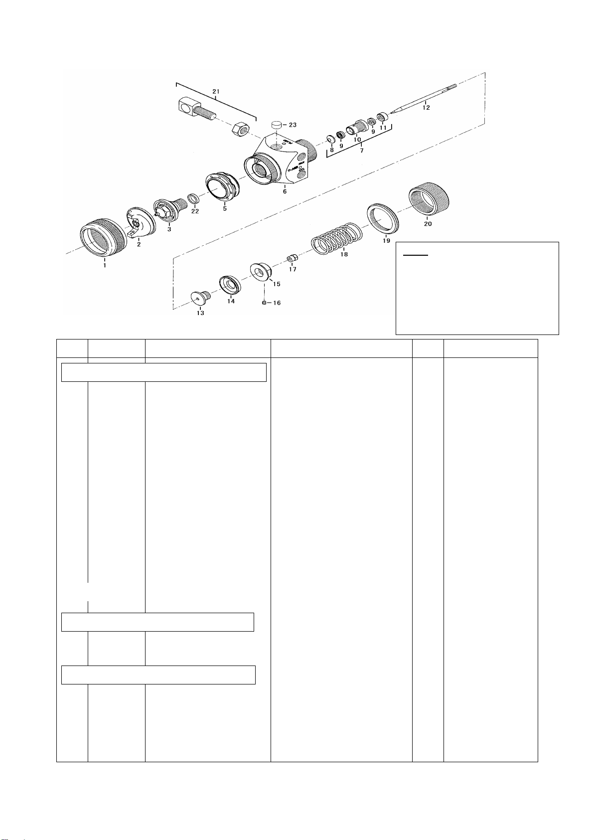
872,873,874 Stainless Body (Standard &Common Parts)
1MBC-368 Retaining Ring 1
2See Below Air Cap 1
3See Below Fluid Tip 1
5MBC-142-1 Plastic Baffle 1
6------- Gun Body (SUS303) 1Not for sale
7T-AGB-10-1 Needle Seal Kit 1
8T-AGB-11-3 Seal Washer 1
9T-AGB-12 Seal 2
10 T-AGB-13-2 Housing 1
11 T-AGB-14 Gland 1
12 See Below Needle 1
13 T-AGB-101 Piston Flange 1
14 T-AGB-102 Piston Cup 1
15 T-AGB-103 Retainer 1
16 T-AGB-104-K5 Set Screw Kit of 5 1
17 T-AGB-105 Lock Nut 1
18 T-AGB-106 Needle Spring 1
19 T-AGB-127 Lock Nut (SUS303) 1
20 T-AGB-128 Adjusting Screw (SUS303) 1
21 T-AGB-109 Gun Stud (with Lock Nut) 1
22 T-AGB-120-K5 Nozzle Gasket Kit of 5 1
23 T-AGB-121-K5 Fluid Plug Kit of 5 1
T-AGB-GRT-1 Grand Removal Tool
T-AGB-HW-1 Housing Wrench
6------- Gun Body (With Blue Anodized Aluminum) 1Not for sale
19 T-AGB-117 Lock Nut (With Blue Anodized Aluminum) 1
20 T-AGB-118
Adjusting Screw (With Blue Anodized Aluminum
1
879 All Stainless Steel Body Type
1T-MBC-368-SUS Retaining Ring (SUS303) 1
7T-AGB-10-1-SUS Needle Seal Kit (SUS303) 1
10 T-AGB-13-2-SUS Housing (SUS303) 1
11 T-AGB-14-SUS Gland (SUS303) 1
13 T-AGB-101-SUS Piston Flange (SUS303) 1
15 T-AGB-103-SUS Retainer (SUS303) 1
17 T-AGB-105-SUS Lock Nut (SUS303) 1
21 T-AGB-109-SUS Gun Stud (SUS303, with Lock Nut) 1
882 High Grade Stainless Steel Body Type
1T-MBC-368-SUS Retaining Ring (SUS303) 1
6------- Gun Body (SUS316) 1Not for sale
7T-AGB-10-1-SUS Needle Seal Kit (SUS303) 1
10 T-AGB-13-2-SUS Housing (SUS303) 1
11 T-AGB-14-SUS Gland (SUS303) 1
13 T-AGB-101-SUS Piston Flange (SUS303) 1
15 T-AGB-103-SUS Retainer (SUS303) 1
17 T-AGB-105-SUS Lock Nut (SUS303) 1
21 T-AGB-109-SUS Gun Stud (SUS303, with Lock Nut) 1
2
(with Retaining Ring)
MB-4039-62 (AC Fluid Tip)
MB-4039-64 (D Fluid Tip)
MB-4039-67 (EE, E Fluid Tip)
2
(without Retaining Ring)
AV-1239-265R-1 (FX,FF,E Fluid Tip)
AV-1239-704 (G,FX,FF,E Fluid Tip)
AV-1239-705 (G,FX,FF Fluid Tip)
AV-1239-765 (FX,FF,E Fluid Tip)
31767-777 (FX,FF,E Fluid Tip)