Webasto GSE CAN User manual

Webasto Charging Systems, Inc.Page 1 of 16
30312-76_02
Charger BMS GCAN Installation Guide
Charger Battery Management System
GSE CAN Installation Guide
Revised 08/2022

30312-76_02 Webasto Charging Systems, Inc.Page 2 of 16
Charger BMS GCAN Installation Guide
© 2022 Webasto Charging Systems, Inc. All rights reserved.
PosiCharge™ systems is a product line of Webasto Charging Systems, Inc. Webasto and the Webasto logo
are trademarks of Webasto Charging Systems, Inc. Corporate names, trademarks, registered trademarks,
service marks, symbols, and logos stated herein are property of their respective companies. Specications are
subject to change without notice. Images of the power cycling and test systems are representative; production
models may vary. No portion of these materials may be duplicated, used, or disclosed without prior written
permission from Webasto Charging Systems, Inc.
Disclaimer: this manual includes the latest information available at the time of printing. Webasto Charging
Systems, Inc. Reserves the right to make changes to this manual and/or product without further notice.
Changes or modications to this product not completed by an authorized service provider could void the
product warranty.
These commodities, technology or software were exported from the United States in accordance with the
Export Administration Regulations. Diversion contrary to US law prohibited
PosiCharge™ systems, a product line of Webasto Charging Systems, Inc..
© 2022 Webasto Charging Systems Inc.

Webasto Charging Systems, Inc.Page 3 of 16
30312-76_02
Charger BMS GCAN Installation Guide
CONTENTS
1 – SAFETY PRECAUTIONS – READ BEFORE USING.................................................................... 5
1.1 – Symbol Usage ........................................................................................................................... 5
2 – GENERAL INFORMATION.............................................................................................................. 5
2.1 – Document Purpose.................................................................................................................... 5
2.2 – GCAN Board.............................................................................................................................. 5
Figure 1 – GCAN Board 29974 and Ribbon Cable............................................................................. 6
2.3 – GSE Charger Decal................................................................................................................... 7
Figure 2 – GCAN Sticker Placement .................................................................................................. 7
3 – GCAN BOARD INSTALLATION PROCESS.................................................................................. 8
3.1 – Updating the Charger Software Version .................................................................................... 8
3.2 – Powering OFF the GSE Charger............................................................................................... 8
3.3 – Installing the GCAN Board ........................................................................................................ 9
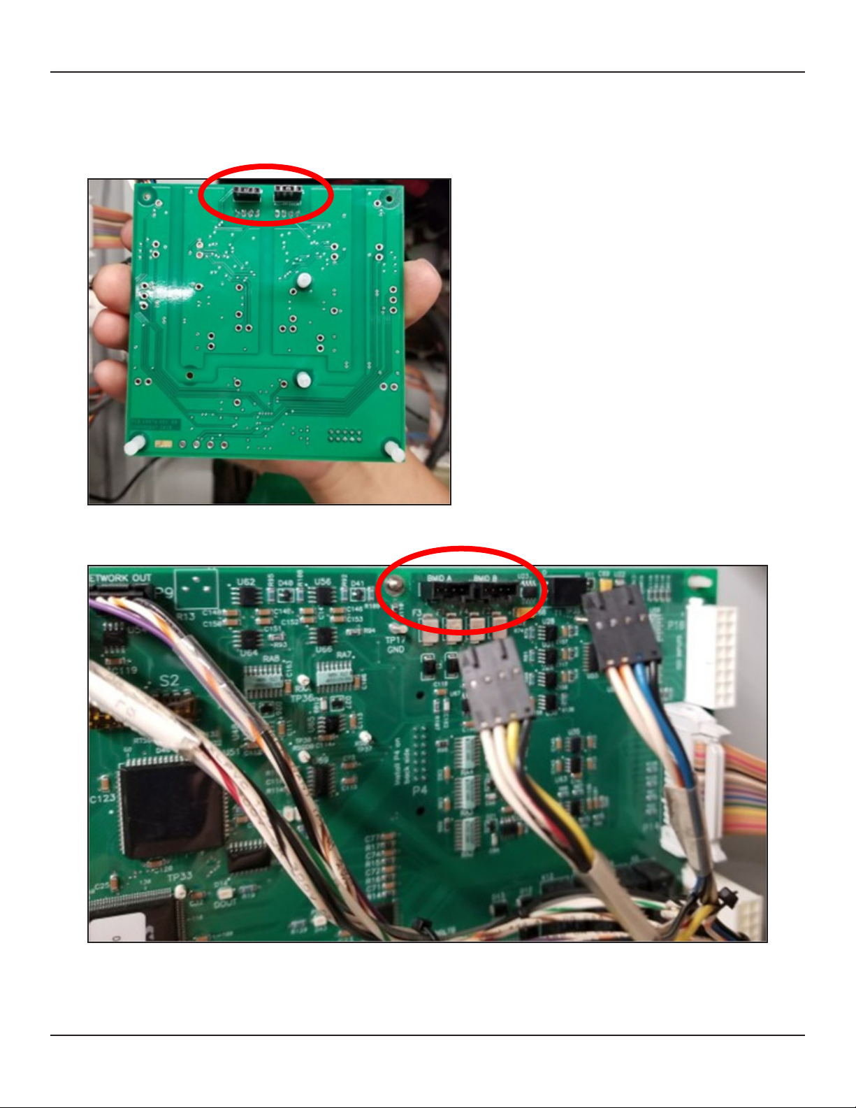
Figure 3 – P6 and P7 Cables Connected to BMID A and BMID B Ports ............................................ 9
Figure 5 – BMID A and BMID B Ports............................................................................................... 10
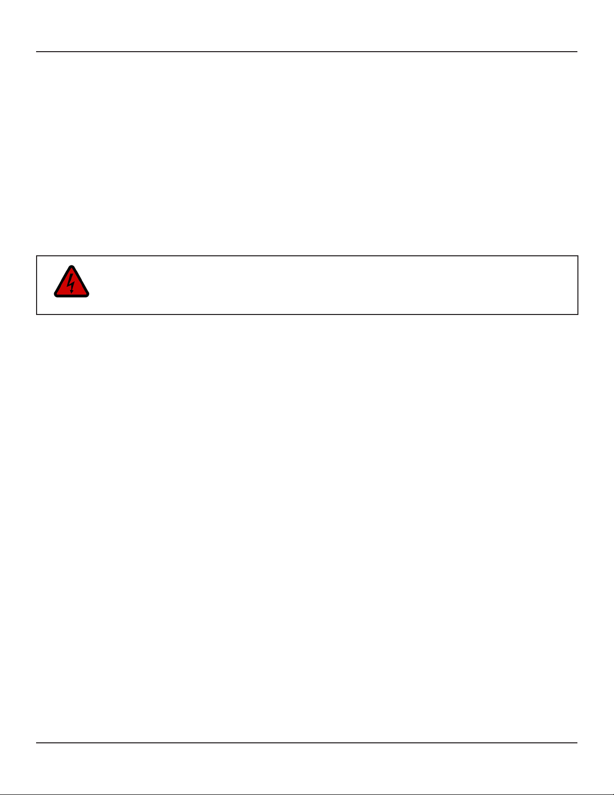
Figure 4 – GCAN Board Connectors ................................................................................................ 10
Figure 6 – Gently press the board into place.....................................................................................11
Figure 7 – GCAN Board Connected to the GSE Control Board ........................................................11
Figure 8 – GCAN Board Connected to the 5VDC Supply at Port 25................................................ 12
Figure 9 P6 and P7 Cables on the GSE Control Board.................................................................... 13
3.4 – The baud rate and other functions can be controlled using the DIP switches......................... 14
3.5 – Powering the GSE charger ON again...................................................................................... 14
Figure 10 – Location of DIP Switches on the GCAN Board ............................................................. 14

30312-76_02 Webasto Charging Systems, Inc.Page 4 of 16
Charger BMS GCAN Installation Guide
This page left intentionally blank.

Webasto Charging Systems, Inc.Page 5 of 16
30312-76_02
Charger BMS GCAN Installation Guide
1 – SAFETY PRECAUTIONS – READ BEFORE USING
The following safety precautions must be read and observed.
• The ground support equipment (GSE) controller area network (CAN) (GCAN) board is designed with
the safety of the user as the highest priority.
• The GCAN board design is such that the installer can safely install it.
• Installation must comply with all local codes.
• The GCAN board supports safe operation of basic charging functions by a user.
1.1 – Symbol Usage
Take special note of the information in this manual marked with the following symbol.
DANGER
Indicates information about safety practices which, if not followed, may result in death or
serious injury.
2 – GENERAL INFORMATION
2.1 – Document Purpose
The GCAN Installation Guide is intended to provide a production technician with the information and guidance
necessary to install the GCAN board safely onto the GSE control board.
2.2 – GCAN Board
2.2.1 – Description
The ground support equipment (GSE) controller area network (CAN) (GCAN) board is an add-on circuit board that
can be added to the 08067 GSE control board. (All boards are in the power station of the chargers.) The GCAN
board is conformal-coated1similarly to the 08067 GSE control board.
2.2.2 – Purpose
The GCAN board enables the charger communication (comm) lines to get charger information from the battery
information management system (BMS)2via he IPC charger CAN communication protocol. If the GCAN board
detects CAN communication, the charger switches into CAN control mode. If the GCAN board does not detect
CAN communication, the charger uses BMID control mode. This allows the charger to be fully backwards
compatible with existing batteries at the customer site.
1Conformal coating material is a thin polymeric lm that conforms to the contours of a printed circuit board to protect the board
components (Wikipedia).
2BMS controls the charging process and the charger.
3The GCAN board supports both the IPC charger CAN communication protocol and the Chinese recommended national standard
(GB/T) communication protocol.

30312-76_02 Webasto Charging Systems, Inc.Page 6 of 16
Charger BMS GCAN Installation Guide
2.2.3 – Scope
The GCAN board can be used in all GSE chargers, which include DVS300, DVS330, DVS400, MVS, and the
power station.
2.2.4 – Use Case
If a customer plugs a charger into a truck, then the charger automatically detects whether the truck is using
CAN communication and begins charging using the IPC Charger CAN communication protocol.
2.2.5 – Equipment
Equipment Description Quantity Part Number Notes
GCAN package 1 29974
The GCAN package contains the GCAN board 29974 and a ribbon cable (Figure 1).
Figure 1 – GCAN Board 29974 and Ribbon Cable

Webasto Charging Systems, Inc.Page 7 of 16
30312-76_02
Charger BMS GCAN Installation Guide
2.3 – GSE Charger Decal
A GCAN decal (sticker) indicating that the GSE charger is CAN compatible is adhered to the front-panel door
of the charger, on the bottom-right corner near the screws (Figure 2).
Sticker
Figure 2 – GCAN Sticker Placement

30312-76_02 Webasto Charging Systems, Inc.Page 8 of 16
Charger BMS GCAN Installation Guide
3 – GCAN BOARD INSTALLATION PROCESS
A technician should install the GCAN board. Installation must comply with the provisions of all local electrical codes
in the country of installation. The following sections walk technicians through a ve-step installation process.
Step 1
3.1 – Updating the Charger Software Version
3.1.1 – Update the charger software to version 1.015 or later, using the charger tools software. Contact your
local PosiCharge service representative for a copy of the latest software version.
Step 2
3.2 – Powering OFF the GSE Charger
3.2.1 – Power OFF the GSE Charger before installation.
DANGER – RISK OF SHOCK
DANGER – ELECTRIC SHOCK CAN KILL
The GSE charger needs to be powered OFF during installation. Do not restore power to
the charger until the installation is complete. Failure to follow these instructions could result
in shock or electrocution.
• Touching live electrical parts can cause fatal shocks or severe burns.
• The battery terminals are always electrically live, and the output circuit is live
whenever the battery is connected or being charged.
• The input power circuitry and internal circuits are live whenever input power is ON.
• An incorrectly installed or improperly grounded charger is a hazard.
Step 1 – Updating the Charger Software Version
Step 2 – Powering OFF the GSE Charger
Step 3 – Installing the GCAN Board
Step 4 – Conguring the DIP Switches
Step 5 – Powering the GSE Charger Back ON

Webasto Charging Systems, Inc.Page 9 of 16
30312-76_02
Charger BMS GCAN Installation Guide
Step 3
3.3 – Installing the GCAN Board
3.3.1 – Remove the P6 and P7 connectors from the BMID A and BMID B ports on the GSE control board 08067
(Figure 3).
Figure 3 – P6 and P7 Cables Connected to BMID A and BMID B Ports on GSE Control Board 08067

30312-76_02 Webasto Charging Systems, Inc.Page 10 of 16
Charger BMS GCAN Installation Guide
3.3.2 – Connect the GCAN board connectors on the board back (Figure 4) to the BMID A and BMID B ports on
the GSE control board as shown below and on the next page (Figures 4 – 7).
Figure 4 – GCAN Board Connectors
Figure 5 – BMID A and BMID B Ports

Webasto Charging Systems, Inc.Page 11 of 16
30312-76_02
Charger BMS GCAN Installation Guide
Figure 7 – GCAN Board Connected
to the GSE Control Board
Figure 6 – Gently press the GCAN board into place so the stando
snaps into place on the GSE control board as shown above.

30312-76_02 Webasto Charging Systems, Inc.Page 12 of 16
Charger BMS GCAN Installation Guide
3.3.3 – Connect the GCAN board ribbon cable connector to the GCAN board ribbon cable port (Figure
8, A) and the P25 ribbon cable connector to the P25 ribbon cable port (to the 5VDC6supply) (Figure 8,
B) on the GSE control board.
Figure 8 – GCAN Board Connected to the 5VDC Supply at
Port 25 on the GSE Control Board with the Ribbon Cable
6Volts Direct Current
B
A

Webasto Charging Systems, Inc.Page 13 of 16
30312-76_02
Charger BMS GCAN Installation Guide
3.3.4 – Connect the P6 and P7 cables on the GSE control board to the corresponding ports on the
GCAN board (Figure 9).
Figure 9 P6 and P7 Cables on the GSE Control Board Connected
to the Corresponding Ports on the GCAN Board
The GCAN board is placed between the comm cables and the GSE control board. If the charger is powered
ON, the GCAN board detects when a BMS charger using CAN communication is connected to the comm lines.
The GCAN board uses CAN protocols to get charging information from the BMS. The GCAN board then uses
SG commands to pass that information to the GSE control board.

30312-76_02 Webasto Charging Systems, Inc.Page 14 of 16
Charger BMS GCAN Installation Guide
Step 4
Figure 10 – Location of DIP Switches on the GCAN Board when Installed
3.4 – The baud rate and other functions can be controlled using the DIP switches on the GCAN board
– see the table below for the baud rate and other conguration options.
DIP Switch # ON OFF
1 125 kbps 250 kbps
2 Not Used
3 Port A – CAN Mode Only Pot A – CAN and BMID Modes
4 Port B – CAN Mode Only Port B – CAN and BMID Modes
Step 5
3.5 – Powering the GSE charger ON again
3.5.1 – Power the GSE charger back ON again after installation.

Webasto Charging Systems, Inc.Page 15 of 16
30312-76_02
Charger BMS GCAN Installation Guide
This page left intentionally blank.

30312-76_02 Webasto Charging Systems, Inc.Page 16 of 16
Charger BMS GCAN Installation Guide
Webasto Charging Systems, Inc.
1333 S. Mayower Ave., Ste 100
Monrovia, CA 91016
USA
Corporate headquarters:
Friedrichshafener Str. 9
82205 Gilching
Germany
Document No. 30312-76_02 • 08/2022 • © Webasto Charging Systems, Inc., 2022
Table of contents
Other Webasto Industrial Equipment manuals
Popular Industrial Equipment manuals by other brands

Samoa
Samoa LARIUS PNEUMATIC HOIST 200 Operating and maintenance manual

Weidmüller
Weidmüller Wave Series operating instructions

Gamry Instruments
Gamry Instruments Faraday Shield Operator's manual

AUMA
AUMA FQMEx 05.1 Operation manual

Weh
Weh TW221 operating instructions

Amtech
Amtech ADAPT System Startup guide