Mark 7 Evolution User manual

MARK 7® RELOADING EVOLUTION USER MANUAL VERSION 2.0, COPYRIGHT 2020
ALL RIGHTS RESERVED
1
Mark 7® EvolutionTM
User Manual V 2.0
Read this manual. Understand all safety and operating instructions. Failure to comply
with the warnings and instructions may result in serious injury, illness or even death.

2
Mark 7® Reloading EVOLUTION User Manual version 2.0, Copyright 2020
All rights reserved
Table of Contents
Table of Contents .........................................................................................................................................2
Important Safety Instructions.............................................................................................................3
Set-Up Procedures
1. Package contents .........................................................................................................................4
2. Unpacking instructions ................................................................................................................5
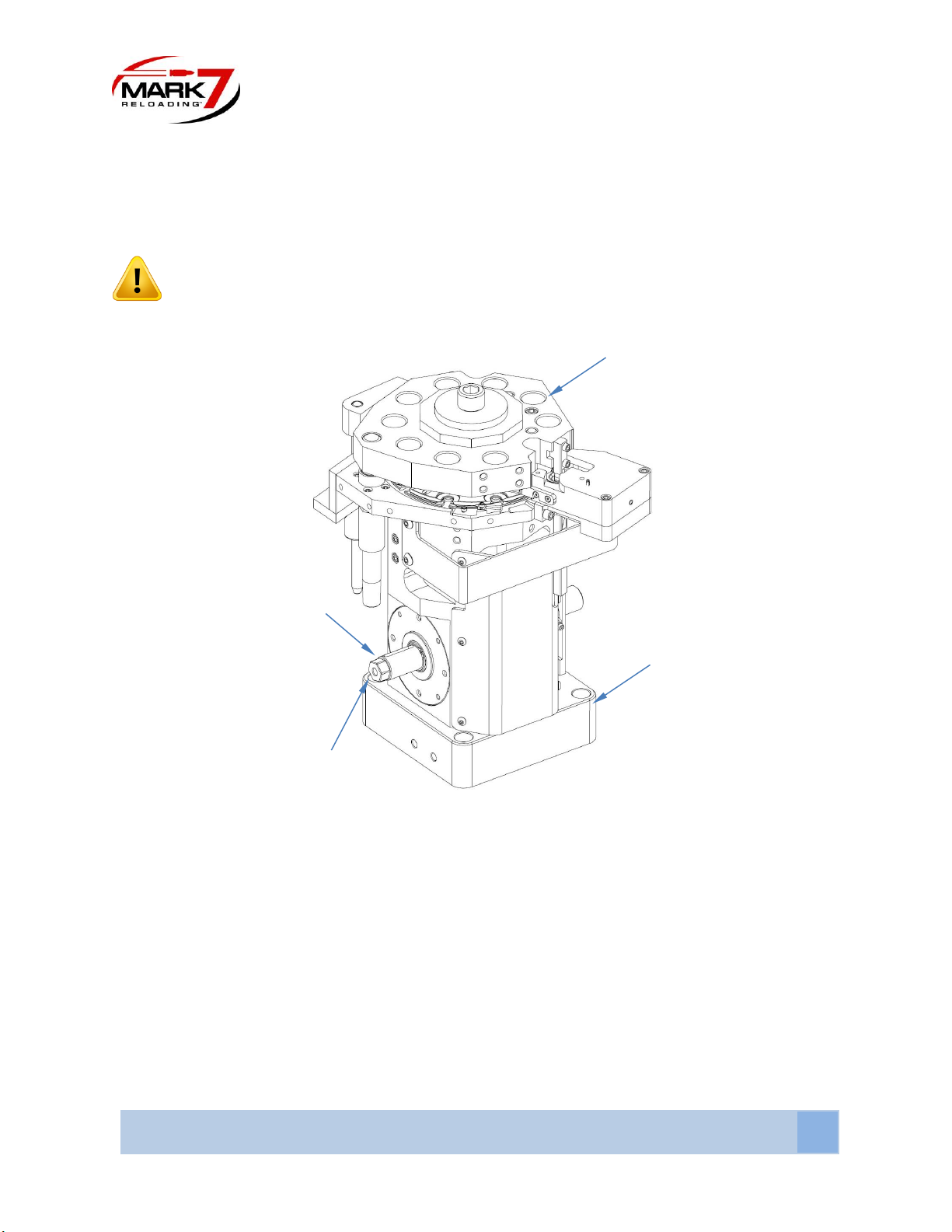
3. Installing Base Plate Feet .............................................................................................................6
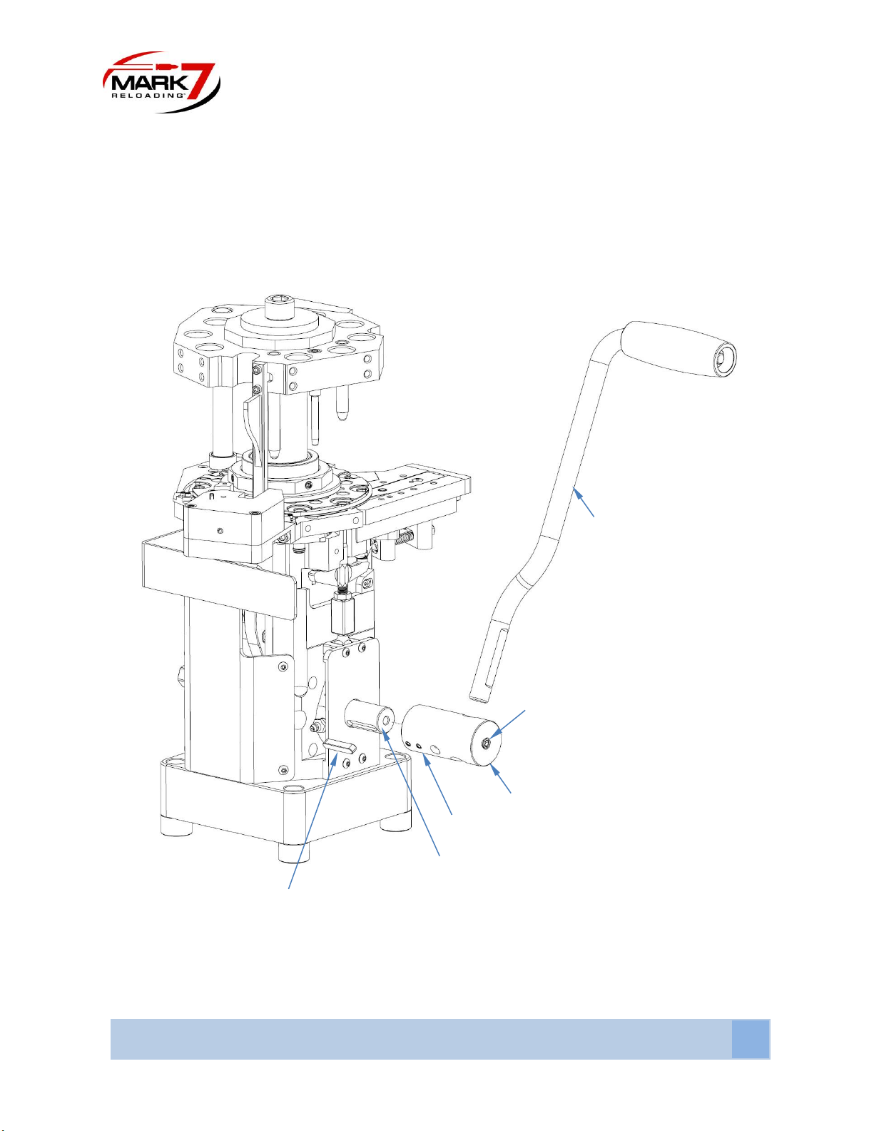
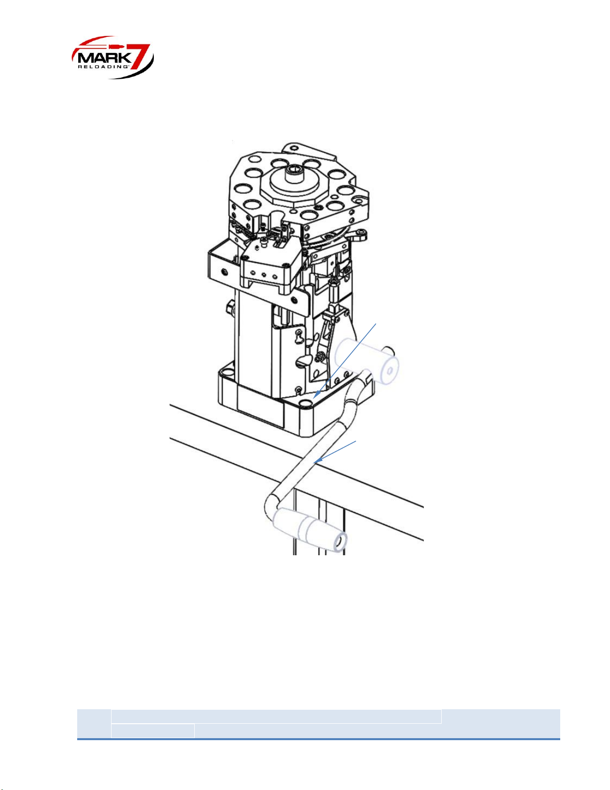
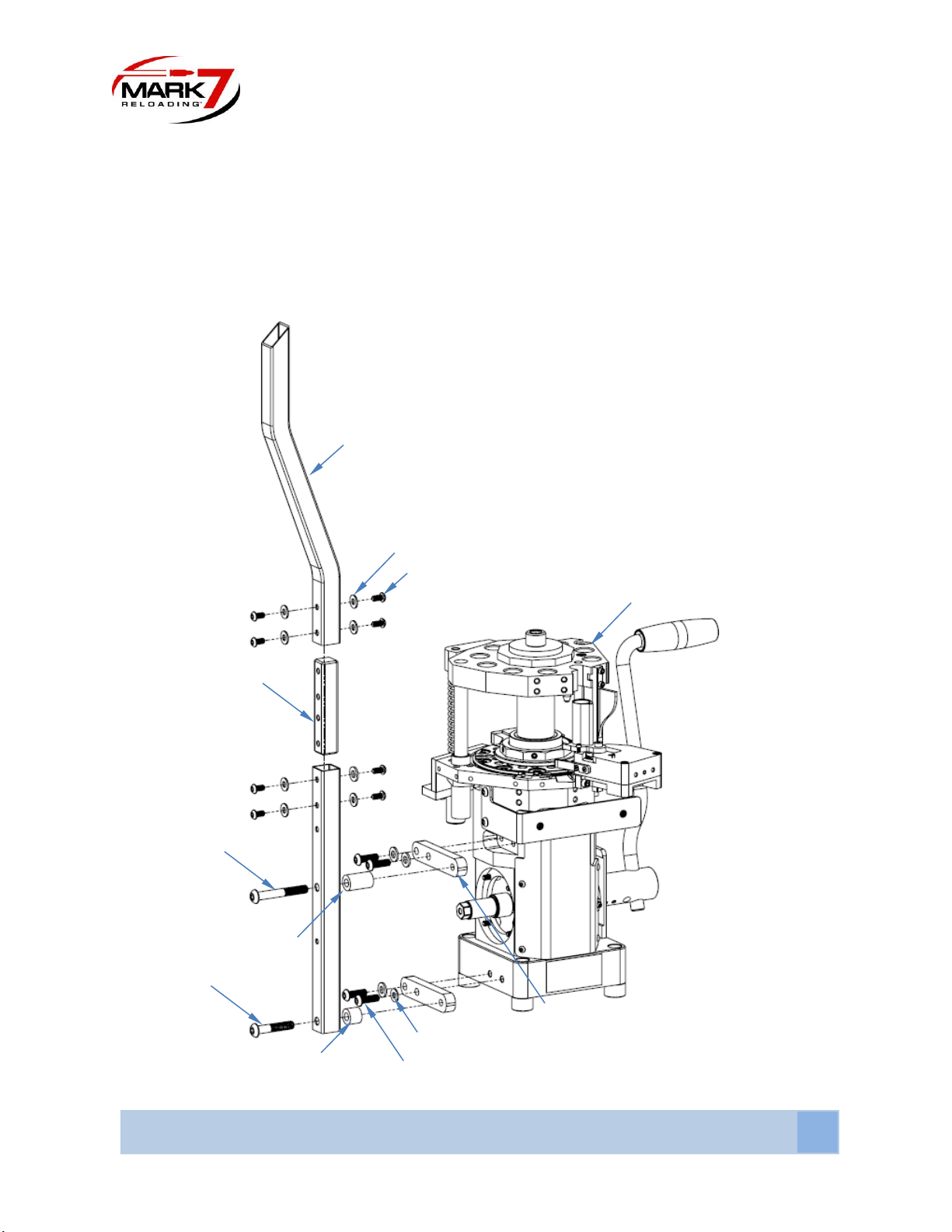
4. Handle Installation and Workbench Mounting ...........................................................................7
5. Case Feeder Installation...............................................................................................................9
6. Installing Case Feeder Spring Flipper Assy.................................................................................11
7. Case Feeder Adapter and Drop Tube Assy.................................................................................12
8. Installing Primer Tube Stack Assy and Low Primer Alarm .........................................................14
9. Powder Measure installation.....................................................................................................16
10. Tool Head Recommended Die Position ...................................................................................16
Operating Instructions
1. Case Feed Univeral Decap or Sizing/Decap - Station 1 and 2....................................................17
2. Swage setup - Station 3..............................................................................................................18
3. Priming seating ..........................................................................................................................18
4. Case Neck Expansion..................................................................................................................19
5. Powder Measure Die hieght and Powder Charge Adjustment..................................................20
6. Setting up Mr.Bulletfeeder and Bullet Drop Assy......................................................................21
7. Bullet Seating/Crimping setup...................................................................................................22
Mark 7 EvolutionTM Recommended Maintenance ...................................................................................23
Shellplate indexing adjustments ...............................................................................................................29
Storage Recommendations........................................................................................................................32
Troubleshooting .......................................................................................................................................32

MARK 7® RELOADING EVOLUTION USER MANUAL VERSION 2.0, COPYRIGHT 2020
ALL RIGHTS RESERVED
3
Important Safety Instructions
Read this manual completely prior to installation and operation. Understand all safety and operating
instructions. Failure to comply with the WARNINGS and instructions may result in serious injury or death.
WARNINGS throughout this manual will be symbolized by the yellow WARNING symbols seen below.
WARNING –Activities using the Mark 7® EvolutionTM are inherently dangerous and may lead to injury and
even death. Actions as a result of using the Mark 7® product are solely the responsibility of the user –if
you get injured through the reloading process or through the use of ammunition as a result of the
reloading process it is your fault.
WARNING - Mark 7® equipment should only be operated by trained personnel that follow all safety
precautions. Failure to do so could result in serious injury or death.
WARNING –Never operate the Mark 7® EvolutionTM while impaired.
WARNING –Never operate the Mark 7® EvolutionTM without using high quality brass and always use
sufficient lubrication on your brass while operating the Mark 7® EvolutionTM.
WARNING –Always wear protective eyewear to protect eyes from being injured. Flying debris may result
when using this equipment. Always wear protective clothing that covers arms, legs and neck to protect
from injury. It is the responsibility of the user to ensure that appropriate protective clothing and
equipment are used to provide protection from those hazards to which personnel are exposed or could
be exposed while working with this product. Failure to do so could result in serious injury or even death.

4
Mark 7® Reloading EVOLUTION User Manual version 2.0, Copyright 2020
All rights reserved
Packaging Contents
The EvolutionTM press is packaged in a single corrugated box (26” X 21” X 16"). The main unit is heavy (60+
lbs.) Please use caution when handling and removing the Main Unit from the packaging.
Item No.
Description
QTY
Item No.
Description
QTY
1
Case Feeder with Caliber Plate
1
21
Main Shaft Crank Key
1
2
Case Feeder Ramp
1
22
3/8"-16 x 4 1/2" Socket Cap Screw
4
3
Case Feeder Spring Flipper Assy
1
23
Base Plate Feet
4
4
Case Feeder Output Spring Assy
1
24
3/8" Screw Washer
4
5
Case Drop Tube
1
25
3/8" Screw Lock Washer
4
6
1/4"-20 x 1/2" Screw
8
26
3/8”-16 Nut
4
7
1/4" Screw Washer
8
27
Spacer 1 1/4" Long
1
8
Case Feed Pole Lower
1
28
Spacer 5/8" Long
1
9
Case Feeder Pole Connector
1
29
5/16" Screw Washer
4
10
Case Feed Pole Upper
1
30
5/16"-24 x 3/4" Screw
4
11
Case Feed Adapter
1
31
Case Feeder Pole Mounting Bracket
2
12
Evolution Main Unit
1
32
3/8"-16 x 2 3/4" Screw
1
13
1/4" -20 x 3/16" Set Screw
2
33
3/8/"-16 x 2" Screw
1
14
Handle
1
34
Zip Tie
4
15
Low Primer Alarm Sensor
1
35
Cable Tie Holder
4
16
Primer Backup Rod
1
36
Case Retention Spring
2
17
Primer Tube Stack Assy
1
37
Shell Plate Retention Spring
2
18
10-32 x 1/2" Flat Head Screw
3
38
1/2" Allen Key
1
19
Mechanical Powder Measure
1
39
AkOffload Bin
1
20
Shaft Handle Adapter
1
1
2
3
4
5
6
7
8
9
10
0
11
0
12
0
13
0
14
0
15
0
16
0
18
0
19
0
20
21
22
23
24
25
26
27
33
28
29
31
32
34
30
17
0
35
36
37
38
39
6

MARK 7® RELOADING EVOLUTION USER MANUAL VERSION 2.0, COPYRIGHT 2020
ALL RIGHTS RESERVED
5
Unpacking instructions
Remove the EvolutionTM Main Unit and place on a clean work surface.
WARNING –The Evolution is shipped with the Tool Head in the down position secured with a
zip tie. The Tool Head is spring loaded with a heavy-duty spring. Before cutting the zip-tie
place an 11/16” wrench on the Main Shaft to secure the Main Unit and gently raise the Tool Head after
the zip tie has been cut.
Figure 1: Cutting Zip tie securing Tool Head
Once the main unit is unpacked and placed on a workbench the EvolutionTM press can be setup and
fitted with the accessories. We recommend the following setup order:
1. Installing Base Plate Feet........................................................................................................ page 6
2. Handle Installation and Workbench Mounting ...................................................................... page 7
3. Case Feeder Installation ......................................................................................................... page 9
4. Installing Case Feeder Spring Flipper Assy ........................................................................... page 11
5. Case Feeder Adapter and Drop Tube Assy ........................................................................... page 12
6. Installing Primer Tube Stack Assy and Low Primer Alarm ................................................... page 14
7. Powder Measure Installation................................................................................................ page 16
Wrench Interface
Tool Head
Main Shaft
Main Unit

6
Mark 7® Reloading EVOLUTION User Manual version 2.0, Copyright 2020
All rights reserved
Installing Base Plate Feet
Thread in Base Plate Feet into Evolution Main Unit Base Plate. Apply grease to the threads for easy
installation.
Figure 2: Installing Base Plate Feet
Evolution Main Unit Base Plate
Base Plate Feet (4X)

MARK 7® RELOADING EVOLUTION USER MANUAL VERSION 2.0, COPYRIGHT 2020
ALL RIGHTS RESERVED
7
Handle Installation and Workbench Mounting
Next determine the location to mount the Main Unit. We recommend you install the Handle first and
lower the Tool Head to the down position to make sure the Handle clears the leading edge of the bench.
The Handle can be installed on either the right side or left side of the press. Insert Main Shaft Crank Key
into Main Shaft key slot as shown in Figure 3. Slide Shaft Handle Adapter over Crank Key and Main
Shaft. Lock in place with the Set Screws (2X.) Insert the Handle Assy into Handle Adapter and secure in
position with the Set Screw.
Figure 3: Installing Handle Assy
Position the press so the handle, while tool head is in the bottom position, does not contact the leading
edge of the workbench. Using the machine as a template mark the 4-hole locations. For reference the
Set Screw
Main Shaft Crank Key
Main Shaft
Set Screw (2X)
(2x)
Handle Adapter
Handle

8
Mark 7® Reloading EVOLUTION User Manual version 2.0, Copyright 2020
All rights reserved
baseplate mounting holes are 5” square and need be large enough to clear a 3/8”-16 socket head screw.
Mounting Hardware is provided with the press.
Figure 4: Mount to workbench with the machine orientated as shown.
Mark thru hole (4X)
Check for clearance

MARK 7® RELOADING EVOLUTION USER MANUAL VERSION 2.0, COPYRIGHT 2020
ALL RIGHTS RESERVED
9
Case Feeder Installation
During the initial assembly leave all screws loose. Wait until the entire assembly is together before doing
the final tightening. Install the Case Feeder Mounting Pole Brackets (2X) to the Evolution Main Unit.
Assemble the Case Feed Pole Lower to the Case Feeder Mounting Pole Brackets with the Screws and
Spacers as shown in Figure 5. Assemble the Case Feed Pole Upper to Case Feed Pole Lower using Case
Feed Pole Connector. Tighten all screws.
Figure 5: Case Feeder Pole Mounting Hardware
Upper Pole
Item 7 (8X)
Item 6 (8X) Washer (4X)
Case Feed Pole Connector
Evolution Main Unit
Item 32
Item 33
Case Feed Mounting Pole Bracket (2X)
Item 29 (4X)
Item 30 (4X)
Item 27
Item 28

10
Mark 7® Reloading EVOLUTION User Manual version 2.0, Copyright 2020
All rights reserved
Place the Case Feeder with Caliber Plate onto Case Feed Pole Upper and slide it down until it is fully
seated. Insert the Caliber Plate into the bowl as shown below. There are 4 Caliber Plates SM P (Small
Pistol), LG P (Large Pistol), SM R (Small Rifle), LG R (Large Rifle.) Confirm the correct plate is included with
the machine caliber.
Figure 6: Installing the Case Feeder with Caliber Plate
Caliber Plate
)
Case Feeder
)
Case Pole Upper
)

MARK 7® RELOADING EVOLUTION USER MANUAL VERSION 2.0, COPYRIGHT 2020
ALL RIGHTS RESERVED
11
Case Feeder Funnel Shim Adjustment: At the opening of the Case Funnel there is a Case Feeder Funnel
Shim that needs to be adjusted to the length of the case to prevent jams in the funnel. For standard
pistol cases keep the opening small (shim to the right.) For tall pistol or rifle move the shim to the left for
a larger opening.
Installing Case Feeder Spring Flipper Assy
Mount the Case Feeder Spring Flipper Assy maintaining a 30 degrees angle in the approximate position
shown below. This prevents cases from getting picked up on their side and clogging the case funnel or
entering the funnel upside-down. Note: do not over-tighten the case feed flipper mount.
Instead of the Case Feeder Spring Flipper Assy you may need to install the Case Feeder Ramp. It is caliber
dependent and you choose which option works best for you.
Figure 7: Case Feeder with Spring Case Feeder Flipper Installed
Case Feeder Spring Flipper Assy
Case Feeder Funnel Shim
)
Case Funnel
)

12
Mark 7® Reloading EVOLUTION User Manual version 2.0, Copyright 2020
All rights reserved
Figure 8: Case Feeder with Case Feeder Ramp installed
Case Feeder Adapter and Drop Tube Assy installation
Install the Case Feed Adapter with shoulder screw and socket cap screw provided to the Case Feed
Upper Housing. The Case Feed Adapter is designed to rotate out 90 degrees for quick removal of cases
in the Drop Tube assy.
Figure 9: Case Feed Adapter installation.
Drop Tube (O-Ring End goes into Adapter)
Case Feeder Ramp
Shoulder Screw
Socket Cap Screw
Case Feed Adapter

MARK 7® RELOADING EVOLUTION USER MANUAL VERSION 2.0, COPYRIGHT 2020
ALL RIGHTS RESERVED
13
Install the Case Feeder Output Spring Assy between the Case Feeder Housing and the Case Drop Tube as
shown below. Note: You may need to thread the spring in/out of the fitting ends to achieve the proper
spring tension/slack.
Figure 10: Case Feeder Assy Installed
Case Feeder Output Spring Assy
Case Feeder Housing
Case Drop Tube

14
Mark 7® Reloading EVOLUTION User Manual version 2.0, Copyright 2020
All rights reserved
Installing Primer Tube Stack Assy and Low Primer Alarm
During the initial assembly leave all screws loose. Wait until the entire assembly is together before doing
the final tightening. Using the 10-32 Flat Head Screws (3X) mount the Primer Tube Stack Assembly to the
Primer Housing.
Figure 11: Installing Primer tube Assy
Primer Tube Stack Assy
10-32 Flat Head Screws (3X)
Primer Housing

MARK 7® RELOADING EVOLUTION USER MANUAL VERSION 2.0, COPYRIGHT 2020
ALL RIGHTS RESERVED
15
Install the PrimerSense® onto the Primer Tube Stack Assembly. Then install the Primer Back Up Rod into
the Primer Tube Stack Assembly. Once the sensor is oriented in the desired position tighten the Set
Screw to lock in place. Back up rod to be installed after loading primers. If installed without primers, press
will not index.
Note: When connecting the Evolution™to the autodrive platform remove the battery
before powering on the machine.
Figure 12: Low Primer Sensor (Front) exploded view
Figure 13: Low Primer Sensor (Rear)
Primer Back up Rod
PrimerSense®
(Low Primer Alarm)
Connector
(Auto drive only. Remove
battery before plugging in)
Set Screw
Primer Tube Stack Assembly

16
Mark 7® Reloading EVOLUTION User Manual version 2.0, Copyright 2020
All rights reserved
Powder Measure Installation
Assemble Powder measure per insert instructions included in powder measure box. Install into station 6
recommended station per Figure 15.
Tool Head Recommended Die Positions
With 9 available Tool Head die locations there are many setups the EvolutionTM can be configured /
customized for to achieve your loading/processing requirements. We recommend the Following setup
for standard processing and loading in one pass.
Figure 14: Tool Head Recommended Die Positions
Station 1:
Case feed
Station 9:
Bullet Seat
Station 8:
Bullet Drop
Station 7:
Powder Check
(not included)
Station 6:
Powder Drop
Station 5:
Case neck Expansion
Expander die
Station 4:
Sizing Die with
Center Pin
Removed
Station 3:
Universal Hold Down
Station 2:
Universal Decap or
Sizing Decap
Station 10:
Bullet Crimp

MARK 7® RELOADING EVOLUTION USER MANUAL VERSION 2.0, COPYRIGHT 2020
ALL RIGHTS RESERVED
17
Operating Instructions
Once the machine is fully assembled and setup, we recommend the following steps to configure the
press for operation
•Determine intended use of machine (processing, loading, processing/loading combined and setup
press accordingly –please feel free to contact us to discuss your requirements.
•Thread the dies into Tool Head but do not set final adjustments at this time –keep dies partially
backed off.
•Cycle the machine a few times without components to ensure smooth operation and is indexing
properly.
1. Case Feed –Universal Decap or Sizing/Decap –Station 1 and 2
Universal decap die can be used as an alternative in station with sizing/decap die. Warning: If universal
decap die is set too far low, it can cause primers to jump and cause primer seating issues.
Add cases to the Case feeder in the caliber that you are loading. Before powering on we recommend
detaching case drop tube from the press and directing it into a bucket and running the case feeder
continuously while watching the cases inside the bowl. Adjust the clutch in the Case feeder plate and the
location of the spring flipper as needed. On the front of the case feeder there is a metal shim that adjusts
the case funnel mouth opening. Keep this opening small for pistol and large for rifle.
Once the Case feeder is dialed in and the cases are feeding properly re-connect the case drop tube for
the press and run a few cases into the machine. Run cases around the shell plate to ensure proper
feeding. Install the Akro bin provided with the press as the case offload.
Remove the cases from the shell plate and move the Tool head to the down position. Thread the sizing
die all the way down so that it just starts to touch the shell plate and lock the die in place. Connect the
decapping hose. Always use case lube when re-sizing once fired cases. Run a few cases through the
sizing die and check cases using a sizing gauge to confirm they are being fully sized and decapped
properly.

18
Mark 7® Reloading EVOLUTION User Manual version 2.0, Copyright 2020
All rights reserved
2. Swage Setup–Station 3
The Evolution™is shipped with the swage rod fully backed off in the down position. We recommend to
cut an empty case in half (cross-section) and insert it into the shell plate in station 3. Always use a hold
down die over the swaging station and never run the machine without the tool head on to avoid
damaging the shellplate during a jam.
•Move the Tool head to the bottom.
•Lower a swage back up die until the center contacts the bottom of the case. Lower the hold
down die a ¼ turn more and lock down.
•Raise the swage rod until the swage rod enters the primer pocket and the shoulder contacts the
bottom of the case. Turn ¼ more and lock in place.
•Remove the case used to adjust the rods and install a case that has been previously decapped.
•Perform a cycle with the case in station 3 -then remove and inspect the primer pocket to
confirm that the pocket is swaged properly. Adjust as needed.
•We recommend using a primer pocket gauge especially if uses crimped/military brass.
3. Primer Seating
The EvolutionTM comes standard with a 100-stack primer tube either configured for SM or LG primers.
Primers can be filled manually using a flip tray and primer pick up tube (included) or using a 3rd party
vibratory feed accessory to fill pick up tubes. We recommend using a sizing die in priming station to
center case to pin properly. Follow the steps below when setting up the priming system:
•Insert 5-10 primers initially into the primer tube assy –install backup rod.
•Cycle the press without a case present to ensure proper primer feeding into the slide.
•Pause with the Tool Head in the down position and verify that the primer punch is inserted in
the shellplate with a primer.
•Place a case that has been decapped and has a verified primer pocket
•Cycle the press –there will be some resistance as you get to the bottom of the stoke –use
caution. Remove the case and check primer insertion depth
•Adjust the primer insertion pin until the proper primer depth is achieved.
There are 3 primer adjustments on the EvolutionTM press –refer to Figure 15.
1. Primer Depth –This adjusts the primer insertion depth –Never adjust more than a ¼ of a
turn without checking new depth.
2. Primer Punch lower height –This adjustment sets the height of the punch when the primer
is fully retracted. It should be flush with the bushing in the primer housing.

MARK 7® RELOADING EVOLUTION USER MANUAL VERSION 2.0, COPYRIGHT 2020
ALL RIGHTS RESERVED
19
3. Primer slide limit- This adjustment sets the location of the slide under the tube stack for
primer feeding.
A sizing die with the center removed can be used to hold down the cases in station 4 in order to
provide additional support to the cases during primer insertion.
Figure 15: Primer Adjustments
WARNING –Never install more than 100 Primers at once. Always wear protective eyewear
and hearing protection when loading primers into the machine and loading. Activities using the Mark 7®
EvolutionTM are inherently dangerous and may lead to injury and even death.
# 1
# 2
# 3

20
Mark 7® Reloading EVOLUTION User Manual version 2.0, Copyright 2020
All rights reserved
4. Case Neck expansion
The EvolutionTM uses a dedicated station for neck expansion/flare in Station 5. For pistol calibers we
recommend using a Lyman Expander die with the Lyman expander powder funnel installed. For rifle there
are several 3rd party expansions dies that can be used including the Lee Universal Flaring die with the rifle
insert. We recommend doing an initial setup at this point to achieve just enough flare for the bullet to fit
inside the case mouth. The final adjustment is best to be dialed in later during the bullet drop setup.
5. Powder Measure Die Height and Powder Charge Adjustment
Install the Powder Measure onto the Tool Head in Station 6. Set the die height so when a case is present
the upper assembly lifts up and rotates the drum to the complete dump position –Refer to right image in
the figure below. NOTE: If the Powder Measure die height is not set properly the drum may not rotate
fully to the dump position which may cause inconsistent powder charges.
Before filling the powder hopper with powder setup minimal drop (about 2 grains). To do so move plunger
halfway and turn powder adjustment knob all the way in (clockwise) and 5 full turns out
(counterclockwise).
•To set the powder charge place a pre-primed case in station 6 under the Powder Measure.
•Perform a single press cycle to actuate the Powder Measure.
•Verify the Adjustment lever completes the full stroke range as shown in the Figure below. If it
doesn’t adjust die height.
•Remove the case and weigh the charge.
•Empty the case and adjust the charge to the desired level by turning the adjustment knob. Turning
clockwise will decrease the charge, counter clock wise will increase the charge.
•Once the desired charge is achieved perform a few dumps –We recommend checking a minimum
of 5 dumps to make sure the charge is consistent. Note: Always discard the first powder dump
after making a charge adjustment and make sure to allow for enough drop time for a given load
by pausing at the bottom of the stroke before returning the Tool Head to the top of the stoke.
•Check the die nut and adjustment charge nut for tightness.
Other manuals for Evolution
1
Table of contents
Other Mark 7 Industrial Equipment manuals
Popular Industrial Equipment manuals by other brands

PCB Piezotronics
PCB Piezotronics 477A07 Installation and operating manual

Grundfos
Grundfos FireSAFE+ instructions

Balluff
Balluff BTL7-E508-M P-S32/KA Series user guide

Schmalz
Schmalz SCG Series operating instructions

Lissmac
Lissmac SBM-M 1000 D2 operating manual

Siemens
Siemens SINUMERIK ONE MCP 2400 Equipment manual