HORNER OEE Solution User manual

MAN1348-01-EN_OEE_UM
August 10, 2022

MAN1348-01-EN_OEE_UM
August 10, 2022 2 | P a g e
PREFACE
This manual explains how to use the Horner OEE Solution.
Copyright© 2022 Horner APG, LLC, 59 South State Avenue, Indianapolis, Indiana 46201. All rights
reserved. No part of this publication may be reproduced, transmitted, transcribed, stored in a retrieval
system, or translated into any language or computer language, in any form by any means, electronic,
mechanical, magnetic, optical, chemical, manual or otherwise, without the prior agreement and written
permission of Horner APG, Inc.
All software described in this document or media is also copyrighted material subject to the terms and
conditions of the Horner Software License Agreement.
Information in this document is subject to change without notice and does not represent a commitment
on the part of Horner APG.
Ethernet™ is a trademark of Xerox Corporation.
microSD™ is a registered trademark of SanDisk Corporation.
LIMITED WARRANTY AND LIMITATION OF LIABILITY
For more information about the warranty and limitation of liability, please contact the Horner Solutions
Group Manager at 877-665-5666 or visit our website at www.hornersolution.com

MAN1348-01-EN_OEE_UM
August 10, 2022 3 | P a g e
Table of Contents
PREFACE............................................................................................................................................2
LIMITED WARRANTY AND LIMITATION OF LIABILITY ...........................................................................2
Table of Contents ......................................................................................................................................3
1 SAFETY AND COMPLIANCE.............................................................................................................5
1.1 Safety Warnings and Guidelines.................................................................................................5
2 INTRODUCTION..............................................................................................................................7
2.1 OEE Overview..............................................................................................................................7
2.2 Production Data Availability .......................................................................................................8
2.3 Types of Reports .........................................................................................................................8
2.4 Contractual Requirements..........................................................................................................8
3 ELECTRICAL INSTALLATION ............................................................................................................9
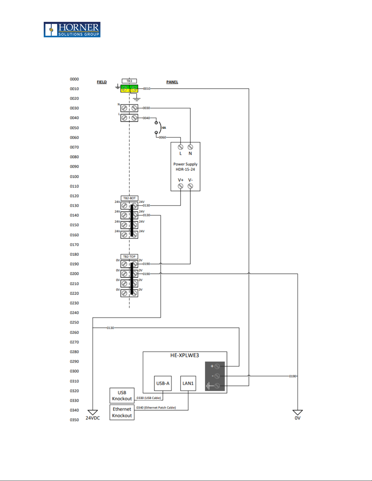
3.1 OEE Power Wiring.......................................................................................................................9
3.2 OEE Electrical I/O......................................................................................................................10
4 ELECTRICAL - GROUNDING...........................................................................................................11
4.1 Grounding Definition ................................................................................................................11
4.2 Ground Specifications...............................................................................................................11
4.3 How to Test for Good Ground ..................................................................................................11
5 OEE SYSTEM NAVIGATION...........................................................................................................12
5.1 Home.........................................................................................................................................12
5.2 Trends .......................................................................................................................................14
5.3 Summary...................................................................................................................................17
5.4 Events........................................................................................................................................17
5.5 Downtime Accumulators ..........................................................................................................18
5.6 Call Accumulators .....................................................................................................................18
6 CALLS............................................................................................................................................19
6.1 Placing a Call .............................................................................................................................19
6.2 Acknowledging a Call................................................................................................................20
6.3 Clearing a Call............................................................................................................................20
7 CONFIGURATION..........................................................................................................................22
7.1 Configuration Overview............................................................................................................22
7.2 Cell Configuration .....................................................................................................................23
7.3 Shift Configuration....................................................................................................................26
7.4 Part Editor/Viewer....................................................................................................................28
7.5 Downtime Code Configuration .................................................................................................32
7.6 Ethernet Configuration.............................................................................................................33
7.7 Email Configuration ..................................................................................................................36
7.8 System Information ..................................................................................................................38
8 OEE SCORE CALCULATION OVERVIEW.........................................................................................39
8.1 Availability.................................................................................................................................39
8.2 Performance .............................................................................................................................39
8.3 Quality.......................................................................................................................................39
8.4 Overall Equipment Effectiveness..............................................................................................39
8.5 Scheduled Breaks and Changeover; Effect on Scoring .............................................................39
9 LOGIN / LOGOUT..........................................................................................................................41
9.1 Log In.........................................................................................................................................41

MAN1348-01-EN_OEE_UM
August 10, 2022 4 | P a g e
8.2 Log Out......................................................................................................................................43
10 WORK INTERFACES ......................................................................................................................44
10.1 Work: Detailed ......................................................................................................................44
10.2 Work: Simplified....................................................................................................................47
10.3 Work: Basic............................................................................................................................49
11 DOWNTIME..................................................................................................................................50
11.1 Manual Downtime.................................................................................................................50
11.2 Automatic Downtime............................................................................................................50
11.3 Downtime Code Prompt........................................................................................................50
11.4 Automatic Downtime Code Entry .........................................................................................51
12 PART CHANGEOVER.....................................................................................................................52
12.1 Changeover Mode.................................................................................................................53
13 DATA LOGGING AND STORAGE....................................................................................................54
13.1 Data Logging..........................................................................................................................54
13.2 Data Log Transfer ..................................................................................................................56
13.3 Configuration Storage ...........................................................................................................56
14 CONFIGURATION UTILITY.............................................................................................................58
14.1 Part Configuration.................................................................................................................59
14.2 Shift Configuration ................................................................................................................62
14.3 Downtime Code Configuration .............................................................................................65
14.4 Login Configuration...............................................................................................................66
14.5 Email / SMS Configuration ....................................................................................................68
14.6 File Locations.........................................................................................................................68
15 DATA CONCENTRATOR ................................................................................................................69
15.1 Configuration.........................................................................................................................70
15.2 Web Browser Access.............................................................................................................71
16 MODBUS TCP ACCESS ..................................................................................................................73
16.1 Configuration Information ....................................................................................................73
16.2 OEE Data................................................................................................................................74
16.3 Light Tower and Call Status...................................................................................................75
17 CONTACT INFORMATION.............................................................................................................75
INDEX..............................................................................................................................................76

MAN1348-01-EN_OEE_UM
August 10, 2022 5 | P a g e
1SAFETY AND COMPLIANCE
1.1 Safety Warnings and Guidelines
When found on the product, the following symbols specify:
Warning: Consult user documentation.
Warning: Electrical Shock Hazard.
WARNING –EXPLOSION HAZARD –Do not disconnect equipment unless power has been switched off or
the area is known to be non-hazardous
WARNING: To avoid the risk of electric shock or burns, always connect the safety (or earth) ground
before making any other connections.
WARNING: To reduce the risk of fire, electrical shock, or physical injury it is strongly recommended to
fuse the voltage measurement inputs. Be sure to locate fuses as close to the source as possible.
WARNING: Replace fuse with the same type and rating to provide protection against risk of fire and
shock hazards.
WARNING: In the event of repeated failure, do not replace the fuse again as a repeated failure indicates
a defective condition that will not clear by replacing the fuse.
WARNING—EXPLOSION HAZARD—Substitution of components may impair suitability for Class I,
Division 2
WARNING: The USB parts are for operational maintenance only. Do not leave permanently connected
unless area is known to be non-hazardous
WARNING—EXPLOSION HAZARD—BATTERIES MUST ONLY BE CHANGED IN AN AREA KNOWN TO BE
NON-HAZARDOUS.
WARNING: Battery May Explode If Mistreated. Do Not Recharge, Disassemble or Dispose Of In Fire.
WARNING: Only qualified electrical personnel familiar with the construction and operation of this
equipment and the hazards involved should install, adjust, operate, or service this equipment. Read
and understand this manual and other applicable manuals in their entirety before proceeding. Failure
to observe this precaution could result in severe bodily injury or loss of life.

MAN1348-01-EN_OEE_UM
August 10, 2022 6 | P a g e
All applicable codes and standards need to be followed in the installation of this product.
For I/O wiring (discrete), use the following wire type or equivalent: Belden 9918, 18 AWG or larger.
Adhere to the following safety precautions whenever any type of connection is made to the module.
a) Connect the green safety (earth) ground first before making any other connections.
b) When connecting to electric circuits or pulse-initiating equipment, open their related breakers.
Do not make connections to live power lines.
c) Make connections to the module first; then connect to the circuit to be monitored.
d) Route power wires in a safe manner in accordance with good practice and local codes.
e) Wear proper personal protective equipment including safety glasses and insulated gloves when
making connections to power circuits.
f) Ensure hands, shoes, and floors are dry before making any connection to a power line.
g) Make sure the unit is turned OFF before making connection to terminals. Make sure all circuits
are de-energized before making connections.
h) Before each use, inspect all cables for breaks or cracks in the insulation. Replace immediately if
defective.

MAN1348-01-EN_OEE_UM
August 10, 2022 7 | P a g e
2INTRODUCTION
2.1 OEE Overview
The Horner OEE Solution is a pre-programmed system that is easy and quick to implement with no
further programming development required by the user end. After a simple initialization setup via the
touchscreen interface (CONFIG /SETUP area), the OEE kit will start collecting and monitoring production
data immediately, though more complex configuration is available as well. This Setup should take
around 30 minutes or less.
The OEE kit provides tools for management, including real-time plant and individual work cell level
visibility of all the work cells that have the Horner OEE machine monitoring solution kit installed and
running on the production floor. The system logs uptime, downtime, good parts, bad parts, and it also
gives the operator the ability to flag the work cell as down and designate why the work cell is down. The
system calculates OEE scores in real time as the part run or shift progresses.
Operators also have a Call for Help function (part of lean manufacturing) to call for raw materials,
maintenance, and supervisors. This gives operators further empowerment with ability to define what
might be causing work processes to miss production quotas.
There is no need to write program logic to use the OEE kit. The system comes pre-programmed and
ready to use as soon as configuration parameters are in place specific to the manufacturing facility in
which the system is installed. The program logic that is in place is not normally accessible.
Management can access OEE data and Call for Help data for understanding production timeline,
analysis, and methods to improve the production process.
Designed to be flexible for diverse types of processes, system configuration allows for:
•Manual cycle and scrap triggers via the touchscreen
•Automatic cycle and scrap triggers via input signals from the manufacturing equipment
•Batch mode operation for single part runs where calculations start over for each part change
•Shift mode operation for calculations that encompass multiple part changes in a single shift
•Part configuration that allows for Changeover times to either affect or not affect OEE scoring
•Shift configuration that allows for multiple break times to either affect or not affect OEE scoring
•Remote access to configuration over an Ethernet network
•Email notification of Calls and for shift-end data log files
•A separate configuration utility that makes constant or cumbersome changes to the system
easier to implement

MAN1348-01-EN_OEE_UM
August 10, 2022 8 | P a g e
2.2 Production Data Availability
Production data is available from the touchscreen interface itself, on displays created separate from
those normally used by the production personnel operating the machine. Management can view shift,
day, week and even monthly production data and information.
A separate Data Concentrator allows monitoring of up to 32 OEE stations brought to a single point. The
centralized data can be accessed with any Internet Browser for both large-screen production monitor
viewing and mobile device viewing.
OEE offers three main points of data to gather data to lead to more productive and valuable operating
time:
•Availability Loss –Due to unplanned stops, equipment failure, planned stops, and setup
adjustments.
•Performance Loss –Due to small stops, idling or minor stops, slow cycles, and reduced speed.
•Quality Loss –Due to production rejects, process defects, startup rejects, and reduced yield.
2.3 Types of Reports
Reports offered by OEE:
•Production Log Data is available to all users on the network
•Downtime durations and reason codes
•Call for help, Acknowledge Call and Clear Call for help data log files.
•Log files created in CSV format for the ability to create custom dashboards and reports
2.4 Contractual Requirements
There are contractual requirements and a signed NDA required for anyone that wants access to the
Intellectual Property of the Horner Solutions Group contained in the OEE solution kit for any
customization of the logic already in place.
The OEE Machine Monitoring Solution Program allows configuration changes and adjustments to
parameters that need to be tailored for each customer’s individual work cell requirements. Also, this
program in locked down and password protected from viewing, copying, changing, uploading or
downloading logic, data log setup, or operator interface displays. If a customer, channel partner, or
system integrator would like to modify the program logic, operator interface screens, or data log
information, they must contact the factory to discuss with Horner Solutions Group Manager.
Each of these cases will be handled on a case-by-case basis determined by volume of the opportunity,
who requested the modification. Finally, a signed NDA protecting the IP of this product for the Horner
Solutions Group is needed, including who will support the application changes that are made and what
the costs are that are associated with the individual project requirements.
To contact the factory, please contact the Horner Solutions Group Manager at 877-665-5666.

MAN1348-01-EN_OEE_UM
August 10, 2022 9 | P a g e
3ELECTRICAL INSTALLATION
3.1 OEE Power Wiring

MAN1348-01-EN_OEE_UM
August 10, 2022 10 | P a g e
3.2 OEE Electrical I/O

MAN1348-01-EN_OEE_UM
August 10, 2022 11 | P a g e
4ELECTRICAL - GROUNDING
4.1 Grounding Definition
Ground: The term ground is defined as a conductive connection between a circuit or piece of equipment
and the earth. Grounds are fundamentally used to protect an application from harmful interference causing
either physical damage such as by lightning or voltage transients or from circuit disruption often caused by
radio frequency interference (RFI). Grounding is also for the safety of the user.
4.2 Ground Specifications
Ideally, a ground resistance measurement from equipment to earth ground is 0Ω. In reality, it typically is
higher. The U.S. National Electrical Code (NEC) states the resistance to ground shall not exceed 25Ω. Horner
APG recommends less than 15Ωresistance from our equipment to ground. Resistance greater than 25Ωcan
cause undesirable or harmful interference to the device.
4.3 How to Test for Good Ground
To test ground resistance, a Ground Resistance Tester must be used. A typical Ground Resistance Meter Kit
contains a meter, two or three wire leads, and two ground rods. Instructions are supplied for either a two-
point or three-point ground test.
METAL WATER PIPE OR
OTHER GOOD GROUND
GROUND ROD
GROUND
DISCONNECTED
FROM SERVICE
GROUND RESISTANCE METER

MAN1348-01-EN_OEE_UM
August 10, 2022 12 | P a g e
5OEE SYSTEM NAVIGATION
5.1 Home
Home is the central navigation and status screen that displays whenever the system is powered on.
Access to Work interfaces, Trends, Summaries, Downtime accumulators, and other features are
available from Home. All ‘Back’, ‘Exit’, and ‘Home’buttons eventually lead to Home.

MAN1348-01-EN_OEE_UM
August 10, 2022 13 | P a g e
5.1.1 Screen Header
The banner at the top of the screen displays the Cell identifier text and the current Part, as well as the
current system time and date. If downtime is currently active, a notification is displayed here.
The Downtime description may display as ‘No Code’ if the reason for Downtime has not yet been
specified. Users are forced to specify a Downtime Code before any further manual operation can occur,
but only from the Work interfaces. This is to keep from interrupting other operations such as system
configuration or viewing historical data.
The background color of many displays can be linked to the current Light Tower color, such as the red
background shown in the Home display above. (See: 7.2.8 Screen Background)
5.1.2 User
The current user is included in log entries made by the OEE system. A user must be logged in to be able
to use the Work interfaces.. If no user is logged in, the box will show a ‘LOG IN’ button If a user is
currently logged in, the User area will show the current user along with a ‘LOG OUT’ button. Both the
‘LOG IN’ and ‘LOG OUT’ buttons result in navigation to either the Log In interface or the Log Out
interface. Once those operations are complete, the system returns to the Home display.
See: Chapter 9 LOGIN / LOGOUT
See: 14.4 Login Configuration
5.1.3 Work Interfaces: Detailed, Simplified, Basic
These navigation buttons take the operator to a screen where cycles and scrap can be triggered
manually, Machine Up/Down can be triggered manually, parts can be changed, Downtime Codes
specified, etc.
See: Chapter 10 WORK INTERFACES
5.1.4 Shift Configuration and Status
Configured shift times are displayed. Any shift that is not configured is shown as dashes. A shift that is
currently in progress is highlighted in green.
See: 7.3 Shift Configuration

MAN1348-01-EN_OEE_UM
August 10, 2022 14 | P a g e
See: 14.2 Shift Configuration
5.1.5 System Navigation
Access to Trends, Summaries, Events, Downtime accumulators, Call accumulators, the Call interface, and
OEE Configuration are available via these navigation buttons.
See: 5.2 Trends
See: 5.3 Summary
See: 5.4 Events
See: 5.5 Downtime Accumulators
See: 5.6 Call Accumulators
See: Chapter 6 CALLS
See: Chapter 7 CONFIGURATION
5.1.6 System Status
The Average Cycle Time, Last Cycle Time (most recent cycle), and the Best Cycle Time are displayed. The
current state of the Digital Inputs and Digital Outputs is shown for troubleshooting purposes.
5.1.7 OEE Scores
The running scores for the system are shown in bar graph and numeric format. The bar graph fill and the
numeric data will change colors to reflect the current OEE targets. The current OEE targets are shown to
the right of the running scores.
5.2 Trends
The Trend button accesses a running trend of OEE data that has collected for the past 8 hours. The user
will first see a single trend that includes all OEE data in the same trend. Navigation buttons at the
bottom of the screen provide access to each separate attribute of OEE as well as the total OEE alone.
When viewing any of the single attributes alone (A, P, Q, OEE), pressing the same button again will
return to the trend containing all the attributes together.
The screen background color reflects green/yellow/red according to the current attribute score and the
respective current targets.
Pressing the Home button will return to Home.

MAN1348-01-EN_OEE_UM
August 10, 2022 15 | P a g e
5.2.1 Main Trend Screen –OEE and All Components
5.2.2 Availability Score Trend
5.2.3 Performance Score Trend

MAN1348-01-EN_OEE_UM
August 10, 2022 16 | P a g e
5.2.4 Quality Score Trend
5.2.5 OEE Score Trend

MAN1348-01-EN_OEE_UM
August 10, 2022 17 | P a g e
5.3 Summary
The Summary gives an overview of the current shift and any shifts not currently active that have
completed within the past 24 hours. A block is shown for each 15-minute slice of time during the shift. A
block may be colored grey to indicate it is either in the future or was scheduled break time. The block is
colored Red, Yellow, or Green to reflect the linked score at the end of that time segment.
5.4 Events
An event log is provided to show a timestamped history of system events. Touching the list will display a
window that can be navigated back in time.

MAN1348-01-EN_OEE_UM
August 10, 2022 18 | P a g e
5.5 Downtime Accumulators
The accumulated downtime for each downtime code is shown in a chart format. The total amount of
downtime is shown for each Shift. Scheduled Changeover time that has accumulated is shown. If there is
any unassigned downtime accumulating, it is shown at the top of the screen.
5.6 Call Accumulators
The amount of time each call has been active and unacknowledged is shown for each shift. Only
configured shifts will display.

MAN1348-01-EN_OEE_UM
August 10, 2022 19 | P a g e
6CALLS
The Call interface is available from the Home interface, from all Work interfaces, and from the Login
interface. It allows a machine operator to make calls to one or more departments via light tower
notification and, if configured, e-mail notification.
Accessing this screen is also how a call is acknowledged or cleared by the corresponding department
after they have responded to the call. Depending on e-mail configuration, an e-mail will be sent after a
timeout period if an active call has not been acknowledged.
The Blue light on the OEE Light Tower will flash if there are any unacknowledged active call. The Blue
light will remain solid blue if all active calls have been acknowledged.
The Call button itself, on any interface with a Call button, will reflect an active call by flashing the icon on
the button face.
Pressing any activated Call button will clear that Call. Pressing the ‘CLEAR ALL’ button will clear all active
calls. Calls can be cleared whether they have been acknowledged or not.
6.1 Placing a Call
Access the Call interface by pressing the ‘CALL’ button. The current state of the Calls are shown. Press
the button for the type of call needed. The button will remain pressed in to indicate an Active Call. The
Blue tower light immediately will start to flash, as will the Call icons on all ‘CALL’ buttons.
If configured, an e-mail message is sent when a call becomes active.
The user may Exit the Call interface once a call is placed to continue work or other operations as
needed.

MAN1348-01-EN_OEE_UM
August 10, 2022 20 | P a g e
6.2 Acknowledging a Call
When the appropriate department responds to the Call, they should Acknowledge the Call. Access the
Call Interface, then press the corresponding ‘Acknowledge Call’ button.
If e-mail has been configured and the timeout expires before the Call has been Acknowledged, a follow-
up e-mail is sent to an additional address if so configured.
6.3 Clearing a Call
When someone from the appropriate department addresses the Call issue, they should clear the call.
Access the Call Interface, then press the corresponding “CALLED” button to clear that Call.
Table of contents
Other HORNER Industrial Equipment manuals
Popular Industrial Equipment manuals by other brands

thermital
thermital COROLLA PACK 1000 Series Installation, operation and maintenance manual

Conquip
Conquip COSHH Store user guide

Trotec
Trotec SpeedMarker 1600 operating manual

JJM Boiler Works
JJM Boiler Works CBM-227 Installation, operation and maintenance

Binks
Binks 83Z Service bulletin

ABB
ABB HT608894 Operation manual

ABB
ABB HT614805 original operation manual

Moser
Moser Ro-V 280 Technical documentation

DÜPERTHAL
DÜPERTHAL Smart Box user manual

Timken
Timken Rollon Tecline Use and maintenance

Littelfuse
Littelfuse Industrial Shock Block SB5000 Series manual

Bühler technologies
Bühler technologies GAS 222.21 E 2 Series Installation and operation instruction