DewAir RH-CUBE 18 CZ Supplement

RH-CUBE 18
CZ & HH OUTDOOR UNITS
INSTALLATION & SERVICE MANUAL
All safety information must be followed as provided.
Important! Refer to page 10 in regards to refrigerant charge
This manual is to be used by qualified professionally trained HVAC technicians only.
DewAir does not assume any responsibility for property damage or personal injury due to improper
service procedures or services performed by an unqualified person.
It is the owner's and installer's responsibility to read and comply with all safety warnings information and
instructions. Failure to heed safety information increases the risk of personal injury property damage
and/or product damage.
Copyright © 2019 DewAir Corporation 1 RHC18O-IM v2.11 Sep , 2019
CZGSX14018
HHGSX14024
SAFETY INSTRUCTIONS
READ THE INSTALLATION OPERATION AND MAINTENANCE INSTRUCTIONS CAREFULLY
BEFORE INSTALLING AND OPERATING THIS DEVICE. PROPER ADHERENCE TO THESE
INSTRUCTIONS IS ESSENTIAL TO OBTAIN MAXIMUM BENEFIT FROM YOUR WHOLE
HOUSE DEHUMIDIFIER.
WARNING
WARNING
THIS SYMBOL MEANS IMPORTANT INSTRUCTIONS. FAILURE TO HEED THEM CAN
RESULT IN SERIOUS INJURY OR DEATH.
WARNING
WARNING
THIS SYMBOL MEANS IMPORTANT INSTRUCTIONS. FAILURE TO HEED THEM CAN
RESULT IN SERIOUS INJURY OR DEATH FROM ELECTRIC SHOCK.
CAUTION
CAUTION
THIS SYMBOL MEANS IMPORTANT INSTRUCTIONS. FAILURE TO HEED THEM CAN
RESULT IN INJURY OR MATERIAL PROPERTY DAMAGE
Copyright © 2019 DewAir Corporation 2 RHC18O-IM v2.11 Sep , 2019

Table of Contents
!
"#$!
$$"!
"$$!
$!
$$!
"$%
$%
$&
$'(")&
*+&
$$$
,$
$$-
+-
+$.
$+$.
*.
$
"
/
Copyright © 2019 DewAir Corporation 3 RHC18O-IM v2.11 Sep , 2019

WARNINGS
WARNING
WARNING
DISCONNECT ALL POWER BEFORE SERVICING OR INSTALLING THIS UNIT. MULTIPLE POWER SOURCES MAY BE PRESENT.
FAILURE TO DO SO MAY CAUSE PROPERTY DAMAGE PERSONAL INJURY OR DEATH.
WARNING
WARNING
EVEN THOUGH THIS UNIT IS MECHANICALLY SIMILAR TO A STANDARD SPLIT-AIR AIR CONDITIONER CONDENSER SYSTEM
ITS OPERATION CONDITIONS SUCH AS PRESSURE AND REFRIGERANT CHARGE ARE DIFFERENT. IT IS CRITICAL THAT THE
REFRIGERANT CHARGE PROCEDURE BE FOLLOWED CAREFULLY.
WARNING
WARNING
DEWAIR WILL NOT BE RESPONSIBLE FOR ANY INJURY OR PROPERTY DAMAGE ARISING FROM IMPROPER SERVICE OR
SERVICE PROCEDURES. IF YOU INSTALL OR PERFORM SERVICE ON THIS UNIT YOU ASSUME RESPONSIBILITY FOR ANY
PERSONAL INJURY OR PROPERTY DAMAGE WHICH MAY RESULT. MANY JURISDICTIONS REQUIRE A LICENSE TO INSTALL
OR SERVICE HEATING AND AIR CONDITIONING EQUIPMENT.
WARNING
WARNING
ONLY INDIVIDUALS MEETING (AT A MINIMUM) THE REQUIREMENTS OF AN "ENTRY LEVEL TECHNICIAN" AS SPECIFIED BY
THE AIR-CONDITIONING HEATING AND REFRIGERATION INSTITUTE (AHRI) MAY USE THIS INFORMATION. ATTEMPTING
TO INSTALL OR REPAIR THIS UNIT WITHOUT SUCH BACKGROUND MAY RESULT IN PRODUCT DAMAGE PERSONAL INJURY
OR DEATH.
WARNING
WARNING
THE UNITED STATES ENVIRONMENTAL PROTECTION AGENCY (“EPA”) HAS ISSUED VARIOUS REGULATIONS REGARDING
THE INTRODUCTION AND DISPOSAL OF REFRIGERANTS INTRODUCED INTO THIS UNIT. FAILURE TO FOLLOW THESE
REGULATIONS MAY HARM THE ENVIRONMENT AND CAN LEAD TO THE IMPOSITION OF SUBSTANTIAL FINES. THESE
REGULATIONS MAY VARY BY JURISDICTION. SHOULD QUESTIONS ARISE CONTACT YOUR LOCAL EPA OFFICE.
WARNING
WARNING
TO PREVENT THE RISK OF PROPERTY DAMAGE PERSONAL INJURY OR DEATH DO NOT STORE COMBUSTIBLE MATERIALS
OR USE GASOLINE OR OTHER FLAMMABLE LIQUIDS OR VAPORS IN THE VICINITY OF THIS
APPLIANCE.
Copyright © 2019 DewAir Corporation 4 RHC18O-IM v2.11 Sep , 2019
NOT RECOMMENDED
BOK!
B B B
A AA AA
CCOK!
AAAAAA
OK!
AAA AA
C C
SHIPPING
INSPECTION
Always keep the unit upright; laying the unit on its side or top
may cause equipment damage. Shipping damage and
subsequent investigation is the responsibility of the carrier.
Verify the model number specifications electrical
characteristics and accessories are correct prior to
installation. The distributor or manufacturer will not accept
claims from dealers for transportation damage or installation
of incorrectly shipped units.
CODES &
REGULATIONS
This product is designed and manufactured to comply with
national codes. Installation in accordance with such codes
and/or prevailing local codes/regulations is the responsibility
of the installer. The manufacturer assumes no responsibility
for equipment installed in violation of any codes or
regulations.
Rated performance is achieved after 72 hours of operation.
Rated performance is delivered at the specified airflow. See
Condensing Unit Specifications section for details
The United States Environmental Protection Agency (EPA)
has issued various regulations regarding the introduction
and disposal of refrigerants. Failure to follow these
regulations may harm the environment and can lead to the
imposition of substantial fines. Should you have any
questions please contact the local office of the EPA.
Outdoor units are approved for operation above 55°F in
cooling mode. Operation below 55°F requires the use of an
approved low ambient kit.
Damage to the unit caused by operating the unit in a
structure that is not complete (either as part of new
construction or renovation) is not covered under the
warranty.
INSTALLATION
CONSIDERATIONS
This unit can be located at ground floor level or on flat roofs.
GROUND INSTALLATION
At ground floor level the unit must be on a solid level
foundation that will not shift or settle. To reduce the
possibility of sound transmission the foundation slab should
not be in contact with or be an integral part of the building
foundation. Ensure the foundation is sufficient to support the
unit. A concrete slab raised above ground level provides a
suitable base.
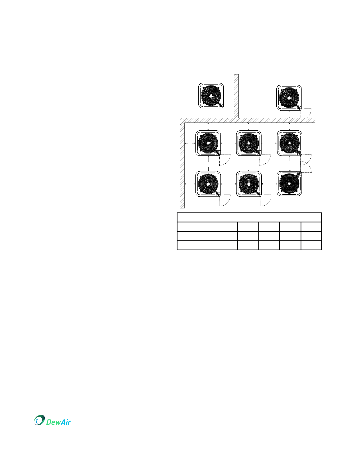
CLEARANCE
Minimum Airflow Clearance
APPLICATION
A B C
AA
Residen ial
10" 10" 18" 20"
Ligh Commercial
12" 12" 18" 24"
ROOFTOP INSTALLATIONS
If it is necessary to install this unit on a roof structure ensure
the roof structure can support the weight and that proper
consideration is given to the weather-tight integrity of the
roof. Since the unit can vibrate during operation sound
vibration transmission should be considered when installing
the unit. Vibration absorbing pads or springs can be installed
between the condensing unit legs or frame and the roof
mounting assembly to reduce noise vibration.
Special consideration must be given to location of the
condensing unit in regard to structures obstructions other
units and any and all other factors that may interfere with air
circulation.
Where possible the top of the unit should be completely
unobstructed; however if vertical conditions require
placement beneath an obstruction there should be a
minimum of 60 inches between the top of the unit and the
obstruction(s).
The specified dimensions meet requirements for air
circulation only. Consult all appropriate regulatory codes
prior to determining final clearances.
Copyright © 2019 DewAir Corporation 5 RHC18O-IM v2.11 Sep , 2019
DO NOT locate the unit:
•Directly beneath a gas appliance termination
vent
•Within 3 feet of a clothes dryer vent.
•Where the refreezing of defrost water would
create a hazard.
Where water may rise into the unit. Another important
consideration in selecting a location for the unit(s) is the
angle to obstructions. Either side adjacent the valves can be
placed toward the structure provided the side away from the
structure maintains minimum service clearance. Corner
ins alla ions are s rongly discouraged.
SAFE REFRIGERANT
HANDLING
While these items will not cover every conceivable situation
they should serve as a useful guide.
Use only refrigerant grade (dehydrated and sealed) copper
tubing to connect the condensing unit with the indoor
evaporator. After cutting the tubing install plugs to keep
refrigerant tubing clean and dry prior to and during
installation. Tubing should always be cut square keeping
ends round and free from burrs. Clean the tubing to prevent
contamination.
Do NOT let refrigerant lines come in direct contact with
plumbing duct work floor joists wall studs floors and
walls. When running refrigerant lines through a foundation or
wall openings should allow for sound and vibration
absorbing material to be placed or installed between tubing
and foundation. Any gap between foundation or wall and
refrigerant lines should be filled with a pliable silicon-based
caulk RTV or a vibration damping material. Avoid
suspending refrigerant tubing from joists and studs with rigid
wire or straps that would come in contact with the tubing.
Use an insulated or suspension type hanger. Keep both
lines separate and always insulate the suction line.
These sizes are recommended for line lengths of 79 feet or
less to obtain optimum performance. For alternate line sizing
options or runs of more than 79 feet contact your distributor
for assistance.
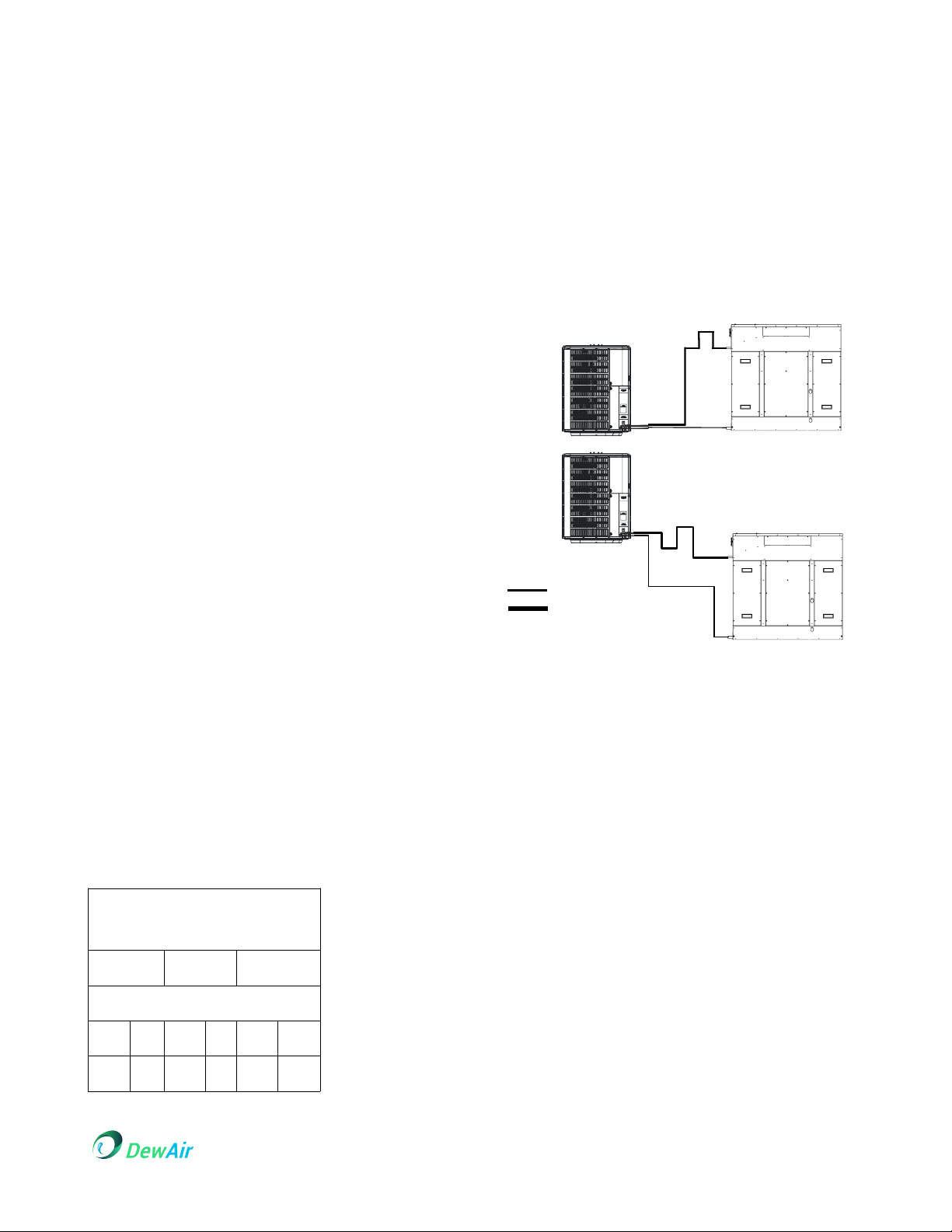
RECOMMENDED
INTERCONNECTING TUBING
0-24 25-49 50-79*
Line Diameter (in. OD)
Suct Liq Suct Liq Suct Liq
5/8 1/4 3/4 38 3/4 3/8
* Lines greater than 79 feet in length or vertical elevation changes
more than 50 feet contact your distributor for assistance.
Mounting the evaporator coil above the condensing
unit will require an inverted loop in the suction line
adjacent or near the connection to the evaporator. The
top of the loop must be slightly higher than the top of
the coil.
Mounting the condensing unit above the evaporator
coil will not require an oil trap in the suction line at the
evaporator except when the condensing unit is over
80 feet above the evaporator.
Insulation is necessary to prevent condensation from
forming and dropping from the suction line. Armflex (or
satisfactory equivalent) with 3/8” min. wall thickness is
recommended. In severe conditions (hot high
humidity areas) 1/2” insulation may be required.
Insulation must be installed in a manner which
protects tubing from damage and contamination.
Where possible drain as much residual compressor
oil from existing systems lines and traps; pay close
attention to low areas where oil may collect. NOTE:
Consult manufacturer before changing refrigerant
types.
BURYING REFRIGERANT LINES
If burying refrigerant lines can not be avoided use the
following checklist.
1. Insulate liquid and suction lines separately.
2. Enclose all underground portions of the refrigerant
lines in waterproof material (conduit or pipe) sealing
the ends where tubing enters/exits the enclosure.
Copyright © 2019 DewAir Corporation 6 RHC18O-IM v2.11 Sep , 2019
$010$0
2$0
3. If the lines must pass under or through a concrete
slab ensure lines are adequately protected and
sealed.
REFRIGERANT LINE CONNECTIONS
IMPORTANT
To avoid overheating the service valve TXV valve or
filter drier while brazing wrap the component with a
wet rag or use a thermal heat trap compound. Be
sure to follow the manufacturer's instruction when
using the heat trap compound. Note: Remove
Schrader valves from service valves before brazing
tubes to the valves. Use a brazing alloy of 2%
minimum silver content. Do not use flux.
Torch heat required to braze tubes of various sizes is
proportional to the size of the tube. Tubes of smaller
size require less heat to bring the tube to brazing
temperature before adding brazing alloy. Applying too
much heat to any tube can melt the tube. Service
personnel must use the appropriate heat level for the
size ofthe tube being brazed. Note: The use of a heat
shield when brazing is recommended to avoid burning
the serial plate or the finish on the unit.
1. The ends of the refrigerant lines must be cut
square deburred cleaned and be round and free
from nicks or dents. Any other condition increases the
chance of a refrigerant leak
2. "Sweep" the refrigerant line with nitrogen or inert
gas during brazing to prevent the formation of copper-
oxide inside the refrigerant lines. The POE oils used in
R410A applications will clean any copper-oxide
present from the inside of the refrigerant lines and
spread it throughout the system. This may cause a
blockage or failure of the metering device.
3. After brazing quench the joints with water or a wet
cloth to prevent overheating of the service valve.
4. Ensure the filter drier paint finish is intact after
brazing. If the paint of the steel filter drier has been
burned or chipped repaint or treat with a rust
preventative. This is especially important on suction
line filter driers which are continually wet when the unit
is operating.
NOTE: Be careful not to kink or dent refrigerant lines.
Kinked or dented lines will cause poor performance or
compressor damage.
Do NOT make final refrigerant line connection until
plugs are removed from refrigerant tubing.
NOTE: Before brazing verify indoor piston size by
checking the piston kit chart packaged with indoor
unit.
LEAK TESTING (NITROGEN OR NITROGEN-
TRACED)
WARNING
WARNING
TO AVOID THE RISK OF FIRE OR EXPLOSION NEVER
USE OXYGEN HIGH PRESSURE AIR OR FLAMMABLE
GASES FOR LEAK TESTING OF REFRIGERATION
SYSTEM.
WARNING
WARNING
TO AVOID POSSIBLE EXPLOSION THE LINE FROM
THE NITROGEN CYLINDER MUST INCLUDE A
PRESSURE REGULATOR AND A PRESSURE RELIEF
VALVE. THE PRESSURE RELIEF VALVE MUST BE SET
TO OPEN AT NO MORE THAN 150 PSIG.
Pressure test the system using dry nitrogen and soapy
water to locate leaks. If you wish to use a leak
detector charge the system to 10 psi using the
appropriate refrigerant then use nitrogen to finish
charging the system to working pressure then apply
the detector to suspect areas. If leaks are found
repair them. After repair repeat the pressure test. If no
leaks exist proceed to system evacuation.
SYSTEM EVACUATION
WARNING
WARNING
REFRIGERANT UNDER PRESSURE!
FAILURE TO FOLLOW PROPER PROCEDURES MAY
CAUSE PROPERTY DAMAGE PERSONAL INJURY OR
DEATH
Condensing unit liquid and suction valves are closed
to contain the charge within the unit. The unit is
shipped with the valve stems closed and caps
installed.
NOTE: Scroll compressors should never be used to
evacuate or pump down a heat pump or air
conditioning system.
NOTE: Prolonged operation at suction pressures less
than 20 psig for more than 5 seconds will result in
overheating of the scrolls and permanent damage to
the scroll tips drive bearings and internal seal.
NOTE: Holding charge must be removed before
brazing.
1. Open service valves before attaching vacuum
pump.
Copyright © 2019 DewAir Corporation 7 RHC18O-IM v2.11 Sep , 2019
2. Connect the vacuum pump with 250 micron
capability to the service valves.
3. Evacuate the system to 250 microns or less using
suction and liquid service valves. Using both valves is
necessary as some compressors create a mechanical
seal separating the sides of the system.
4. Close pump valve and hold vacuum for 10 minutes.
Typically pressure will rise during this period.
• If the pressure rises to 1000 microns or less and
remains steady the system is considered leak-free;
proceed to startup.
• If pressure rises above 1000 microns but holds
steady below 2000 microns moisture and/or non-
condensibles may be present or the system may have
a small leak. Return to step 2: If the same result is
encountered check for leaks as previously indicated
and repair as necessary then repeat evacuation.
• If pressure rises above 2000 microns a leak is
present. Check for leaks as previously indicated and
repair as necessary then repeat evacuation.
LINE SET
INSTALLATION
When installing the line set:
• Make sure the lines are suitable for use with R410a.
• Do not crush the lines and always allow a minimum
bend radius of 2 inches.
• Keep the ends of the lines covered to prevent dirt
and debris from entering the lines during installation.
• Secure the line set to the building with isolating
hardware to prevent vibration transmission to the
building.
• Seal and isolate the opening(s) where the line set is
routed into the building.
• Insulate the gas (suction) line to prevent water
condensation on the gas line.
• Flush the lines with an inert gas before and/or during
brazing to prevent oxidation inside the lines.
• Release the inert gas holding charge and remove the
plugs in the dehumidifier lines before brazing.
• Do not overheat the lines connected to the
dehumidifier or the condensing unit when brazing.
• Be aware of the relative location of the dehumidifier
(Indoor unit) and condensing unit (Outdoor Unit) when
installing the line set.
BRAZING THE LINE SET
WARNING
WARNING
POLYOL ESTER (POE) OILS USED WITH HFC-410A
REFRIGERANT ABSORB MOISTURE VERY QUICKLY. IT
IS VERY IMPORTANT THAT THE REFRIGERANT
SYSTEM BE KEPT CLOSED AS MUCH AS POSSIBLE.
DO NOT REMOVE LINE SET CAPS OR SERVICE
VALVE STUB CAPS UNTIL YOU ARE READY TO MAKE
CONNECTIONS
WARNING
WARNING
WHEN USING A HIGH PRESSURE GAS SUCH AS DRY
NITROGEN TO PRESSURIZE A REFRIGERATION OR
AIR CONDITIONING SYSTEM USE A REGULATOR
THAT CAN CONTROL THE PRESSURE DOWN TO 1 OR
2 PSIG.
CAUTION
CAUTION
BRAZING ALLOYS AND FLUX CONTAIN MATERIALS
WHICH ARE HAZARDOUS TO YOUR HEALTH. AVOID
BREATHING VAPORS OR FUMES FROM BRAZING
OPERATIONS. PERFORM OPERATIONS ONLY IN
WELL-VENTILATED AREAS. WEAR GLOVES AND
PROTECTIVE GOGGLES OR FACE SHIELD TO
PROTECT AGAINST BURNS. WASH HANDS WITH
SOAP AND WATER AFTER HANDLING BRAZING
ALLOYS AND FLUX.
TO PREVENT STRIPPING OF THE VARIOUS CAPS
USED THE APPROPRIATELY SIZED WRENCH SHOULD
BE USED AND FITTED SNUGLY OVER THE CAP
BEFORE TIGHTENING.
ALLOW BRAZE JOINT TO COOL BEFORE
REMOVING THE WET RAG FROM THE SERVICE
VALVE. TEMPERATURES ABOVE 2500 CAN
DAMAGE VALVE SEALS
USE SILVER ALLOY BRAZING RODS WITH 5%
MINIMUM SILVER ALLOY FOR COPPER-TO-COPPER
BRAZING. USE 45% MINIMUM SILVER ALLOY FOR
COPPER-TO-BRASS AND COPPER-TO-STEEL
BRAZING.
Copyright © 2019 DewAir Corporation 8 RHC18O-IM v2.11 Sep , 2019
CAUTION
CAUTION
THE DEHUMIDIFIER IS SHIPPED FROM THE FACTORY
PRESSURIZED WITH A CHARGE OF INERT GAS AND
WITH RUBBER PLUGS IN THE LINES. PURGE THE
INERT GAS FROM THE DEHUMIDIFIER BY REMOVING
THE RUBBER PLUGS IN THE LIQUID AND GAS LINES
TO RELEASE THE INERT GAS BEFORE CONNECTING
THE LINE SET.
Note: If there is no pressure in the dehumidifier when
the first plug is removed check the dehumidifier for
damage and leaks before continuing with the
installation.
WARNING
WARNING
WHEN CHARGING THE SYSTEM FOLLOW THE
INSTRUCTIONS IN SYSTEM STARTUP. THE
PROCEDURE VARIES FROM WHAT IS TYPICAL FOR A
CONDENSER.
Procedure to connect the line set to the Dehumidifier
1. Purge the inert gas from the dehumidifier by
removing the rubber plugs in the liquid and gas lines
to release the inert gas before connecting the line set.
2. Place a field-provided heat shield such as a wet
rag against the dehumidifier and around the piping
stubs. The heat shield must be in place to protect the
cabinet from heat damage.
3. Swage the liquid and gas lines (if necessary) to fit
onto the dehumidifier lines.
4. Purge the dehumidifier lines and the line set with
dry nitrogen (Inert gas) to prevent oxidation during
brazing. Flow dry nitrogen into the lines at a low
pressure of 1 to 2 psig.
5. Braze the line set lines to the dehumidifier lines.
6. Remove the heat shield after brazing and allow the
connections to cool.
ELECTRICAL
CONNECTIONS
WARNING
WARNING
DISCONNECT ALL POWER BEFORE SERVICING OR
INSTALLING THIS UNIT. MULTIPLE POWER SOURCES
MAY BE PRESENT. FAILURE TO DO SO MAY CAUSE
PROPERTY DAMAGE PERSONAL INJURY OR DEATH.
WARNING
WARNING
WIRING MUST CONFORM WITH NEC OR CEC AND
ALL LOCAL CODES. UNDERSIZED WIRES COULD
CAUSE POOR EQUIPMENT PERFORMANCE
EQUIPMENT DAMAGE OR FIRE.
TO AVOID THE RISK OF FIRE OR EQUIPMENT
DAMAGE USE COPPER CONDUCTORS.
The condensing unit rating plate lists pertinent
electrical data necessary for proper electrical service
and over-current protection. Wires should be sized to
limit voltage drop to 2% (max.) from the main breaker
or fuse panel to the condensing unit. Consult the NEC
CEC and all local codes to determine the correct wire
gauge and length.
Local codes often require a disconnect switch located
near the unit; do not install the switch on the unit.
Refer to the installation instructions supplied with the
indoor furnace/air handler for specific wiring
connections and indoor unit configuration. Likewise
consult the instructions packaged with the thermostat
for mounting and location information.
OVER-CURRENT PROTECTION
The following over-current protection devices are
approved for use.
• Time delay fuses
• HACR type circuit breakers
These devices have sufficient time delay to permit the
motor compressor to start and accelerate its load.
Copyright © 2019 DewAir Corporation 9 RHC18O-IM v2.11 Sep , 2019

HIGH VOLTAGE CONNECTIONS
Route power supply and ground wires through the
high voltage port and terminate in accordance with the
wiring diagram provided inside the control panel cover.
LOW VOLTAGE CONNECTIONS
For low voltage connections refer to the Indoor Unit
Installation Manual.
SYSTEM START
UP
WARNING
WARNING
REFRIGERANT UNDER PRESSURE!
• DO NOT OVERCHARGE SYSTEM WITH
REFRIGERANT.
• DO NOT OPERATE UNIT IN A VACUUM OR AT
NEGATIVE PRESSURE.
FAILURE TO FOLLOW PROPER PROCEDURES MAY
CAUSE PROPERTY DAMAGE PERSONAL INJURY OR
DEATH.
CAUTION
CAUTION
POSSIBLE REFRIGERANT LEAK
TO AVOID A POSSIBLE REFRIGERANT LEAK OPEN THE
SERVICE VALVES UNTIL THE TOP OF THE STEM IS 1/8”
FROM THE RETAINER.
When opening valves with retainers open each valve
only until The top of the stem is 1/8” from the retainer.
To avoid loss of refrigerant DO NOT apply pressure to
the retainer. When opening valves without a retainer
remove service valve cap and insert a hex wrench into
the valve stem and back out the stem by turning the
hex wrench counterclockwise. Open the valve until it
contacts the rolled lip of the valve body.
NOTE: These are not back-seating valves. It is not
necessary to force the stem tightly against the rolled
lip. The service valve cap is the secondary seal for the
valves and must be properly tightened to prevent
leaks. Make sure cap is clean and apply refrigerant oil
to threads and sealing surface on inside of cap.
Tighten cap finger-tight and then tighten additional 1/6
of a turn (1 wrench flat) or to the following
specification to properly seat the sealing surfaces.
1. 3/8” valve to 5 - 10 in-lbs
2. 5/8” valve to 5 - 20 in-lbs
3. 3/4” valve to 5 - 20 in-lbs
4. 7/8” valve to 5 - 20 in-lbs
Do not introduce liquid refrigerant from the cylinder
into the crankcase of the compressor as this may
damage the compressor.
CAUTION
CAUTION
POSSIBLE REFRIGERANT LEAK
To avoid a possible refrigerant leak open the service
valves until the top of the stem is 1/8" from the retainer.
1. Break vacuum by fully opening liquid and suction
base valves.
2. Set thermostat to call for cooling. Check indoor and
outdoor fan operation and allow system to stabilize for
10 minutes for fixed orifices and 20 minutes for
expansion valves.
CAUTION
CAUTION
THE CORRECT REFRIGERANT CRITICAL CHARGE IS
NEEDED FOR PROPER OPERATION
WARNING
WARNING
USE REFRIGERANT CERTIFIED TO AHRI STANDARDS.
USE OF USED REFRIGERANT MAY CAUSE
COMPRESSOR DAMAGE THAT IS NOT COVERED UNDER
WARRANTY. MOST PORTABLE MACHINES CANNOT
CLEAN USED REFRIGERANT TO MEET AHRI
STANDARDS..
CAUTION
CAUTION
OPERATING THE COMPRESSOR WITH THE SUCTION
VALVE CLOSED MAY CAUSE SERIOUS COMPRESSOR
DAMAGE.
Copyright © 2019 DewAir Corporation 10 RHC18O-IM v2.11 Sep , 2019

Open the suction service valve first! If the liquid
service valve is opened first oil from the compressor
may be drawn into the indoor coil TXV restricting
refrigerant flow and affecting operation of the system.
After the refrigerant charge has bled into the system
open the liquid service valve. The service valve cap is
the secondary seal for the valves and must be
properly tightened to prevent leaks. Make sure cap is
clean and apply refrigerant oil to threads and sealing
surface on inside of cap. Tighten cap finger-tight and
then tighten additional 1/6 of a turn (1 wrench fiat) or
to the following specification to properly seat the
sealing surfaces.
1. 3/8" valve to 5 - 10 in-Ibs
2. 5/8" valve to 5 - 20 in-Ibs
3. 3/4" valve to 5 - 20 in-Ibs
4.7/8" valve to 5 - 20 in-Ibs
Do not introduce liquid refrigerant from the cylinder
into the
crankcase of the compressor as this may damage the
compressor.
CRITICAL
REFRIGERANT
CHARGE
ADEQUATE REFRIGERANT CHARGE FOR THE EVAPORATOR
COIL AND 15 FEET OF LINESET IS SUPPLIED WITH THE
CONDENSING UNIT. IF LINESET EXCEEDS 15 FEET IN
LENGTH REFRIGERANT SHOULD BE ADDED AT 0.6 OUNCES
PER FOOT OF LIQUID LINE.
Copyright © 2019 DewAir Corporation 11 RHC18O-IM v2.11 Sep , 2019

OUTDOOR UNIT SPECIFICATIONS
NOTE: This data is provided as a guide it is important to electrically connect the unit and properly size fuses/ circuit breakers
and wires in accordance with all national and/or local electrical codes. Use copper wire only.
Part Number GSX14018
(CZ)
GSX14024
(HH)
Cooling Capacity BTUH 18,000 24,000
Compressor
R.L. Amps
L.R. Amps
Decibels
Low Pressure Switch
Open
Close
High Pressure Switch
Open
Close
6.0
37.5
75
22 PSI
50 PSI
6 1 0 P S I
4 2 0 P S I
7.7
38.0
74
22 PSI
50 PSI
6 1 0 P S I
4 2 0 P S I
Condenser Fan Motor
Horsepower
F.L. Amps
1/8
0.65
1/8
0.7
Refrigeration System
Line Size
Liquid Line, Inches O.D.*
Suction Line, Inches O.D.*
Connection Size
Liquid Valve Size (OD)
Suction Valve Size (OD)
Valve Type
Refrigerant Charge
Included Piston
Low Pressure Switch
High Pressure Switch
3/8"
3/4"
3/8"
3/4"
sweat
68
0.051
94 psi
150 psi
3/8"
3/4"
3/8"
3/4"
sweat
72
0.057
94 psi
150 psi
Electrical Data
Voltage-Phase (60 Hz)
Min/Max Volts
Max. Overcurrent Protection
Minimum Circuit Ampacity(1)
208/230-1
197/253
15 A
8.2 A
08/230-1
197/253
15 A
10.3 A
Weights
Equipment Weight
Shipping Weight
102 lb
117 lb
126 lb
141 lb W x D x H
Inches 26 x 26 x 27½
cm 66 x 66 x 70
Copyright © 2019 DewAir Corporation 12 RHC18O-IM v2.11 Sep , 2019
()003456780099:074929557095
;<70=:0:0551059>:003
()*9<088=772"=0?MUST08"59@
7@A0079BC74980397
DW
H

NOTES
_________________________________________________________________________________________
_________________________________________________________________________________________
_________________________________________________________________________________________
_________________________________________________________________________________________
_________________________________________________________________________________________
_________________________________________________________________________________________
_________________________________________________________________________________________
_________________________________________________________________________________________
_________________________________________________________________________________________
_________________________________________________________________________________________
_________________________________________________________________________________________
_________________________________________________________________________________________
_________________________________________________________________________________________
_________________________________________________________________________________________
_________________________________________________________________________________________
_________________________________________________________________________________________
_________________________________________________________________________________________
Copyright © 2019 DewAir Corporation 13 RHC18O-IM v2.11 Sep , 2019
This manual suits for next models
3
Table of contents
Popular Dehumidifier manuals by other brands

Horizon Fitness
Horizon Fitness Titan XP90 Installation and operation manual

Tectro
Tectro TD 1010 operating manual

Royal Sovereign
Royal Sovereign RDH-045EA owner's manual

INVENTOR
INVENTOR DE-MDDF20 user manual

Humidex
Humidex CCC-103E Installation & owner's manual

Pahwa Group
Pahwa Group Delair RD Series Operating, installation and maintenance manual


