10
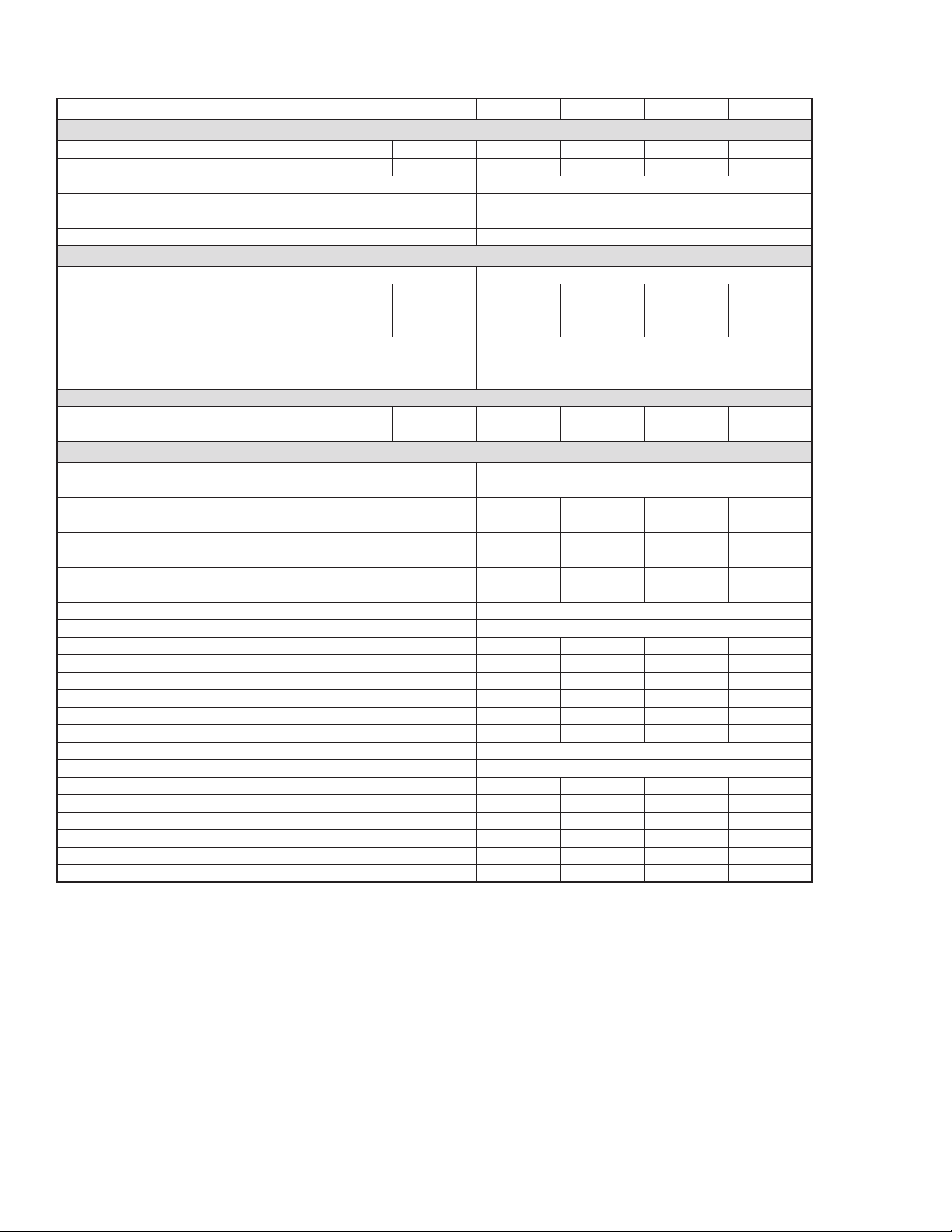
TROUBLESHOOTING GUIDE
SYMPTOM POSSIBLE CAUSE(S) CORRECTIVE ACTION
A. Water downstream of
dryer.
1. Residualfreemoistureremainingin
downstream pipelines.
2. Airby-passsystemisopen.
3. Inletandoutletconnectionsare
reversed.
4. Temperatures surrounding air lines
downstreamofdryerhavedropped
below dryer’s dew point rating.
5. Excessivefreemoisture(bulkliquid)
at dryer inlet.
6. Condensatenotbeingautomatically
drained.
Drainmechanismiscloggedor
inoperative.
Drainlineisrestrictedorfrozen.
7. Dryeroverloadedresultingin
elevated dew point.
8. Refrigerationsystemnot
functioningproperlyresultingin
elevated dew point.
Blow out system with dry air.
Checkvalvepositions.
Checkforcorrectconnection.
Insulateorheattraceairlinesexposedto
low ambients or dry air to lower dew point.
Installseparatoraheadofdryer.
Replacedrainmechanismifinoperative.
Open drain line.
Checkinletairtemperatureandpressure,
owrate(compressorcapacity)and
ambient air temperature.
SeeDbelow.
B. High pressure drop
across dryer.
1. Excessiveairow.
2. Freezingofmoistureinevaporator
becauseofrefrigerationsystem
improperlyfunctioning.
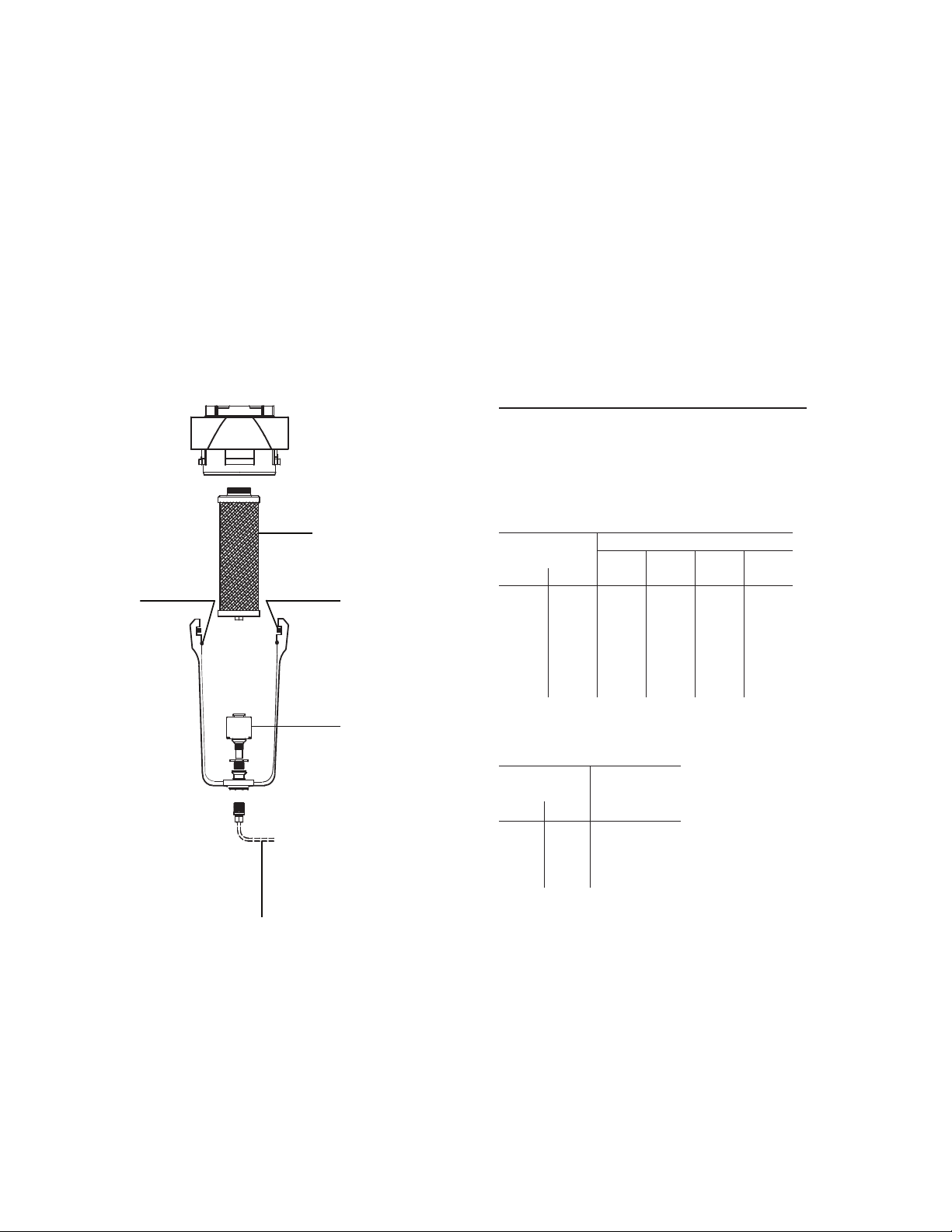
3. Separatororoptionaloilremoval
lterelementclogged.
Checkowrate.
SeeDbelow.
Replacelterelement(s).
C. Dew point indicator
in red area.
1. Dryeroverloadedresultinginhigh
air outlet temperature.
2. Refrigerationsystemnot
functioningproperlyresultingin
high air outlet temperature.
3. Temperature sensor not properly
attached,uninsulated,or
malfunctioning.
SeeA7.
SeeDbelow.
Checksensorbulb.
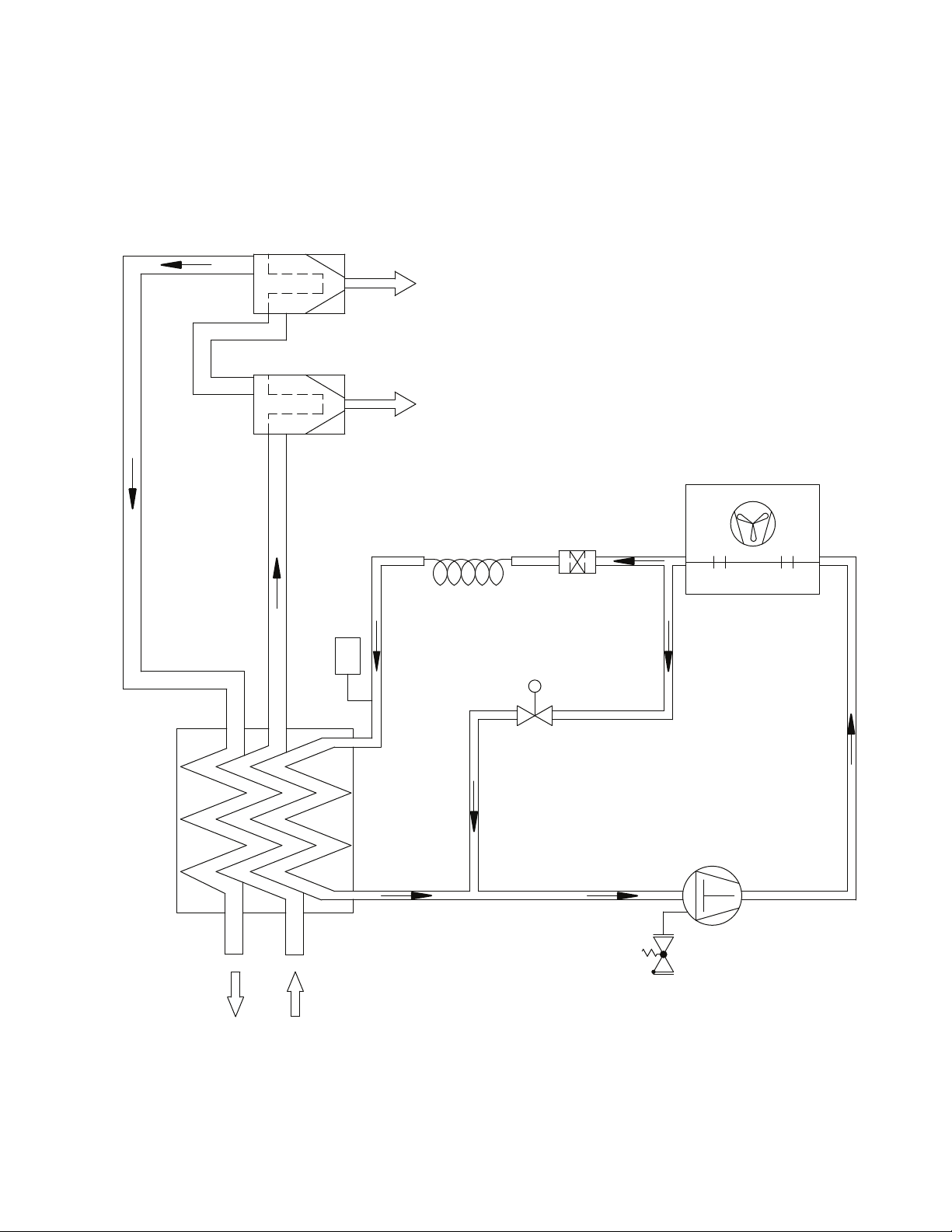
D. Refrigeration system
not functioning
properly.
1. Poweronlightoff.
2. Refrigerantcompressor
cyclesonandoff.
a. ON/OFFswitchis“OFF”.
b. Linedisconnectswitchopen.
c. Blownfuses,openbreaker.
d. Faultywiring,looseterminals.
a. Highorlowambientconditions.
b. Dirty,cloggedcondenserns,
obstructedairowacross
condenser,ornonfunctioningfan
motor.
Turnswitch“ON”.
Close disconnect switch.
Checkforcontinuity.
Haveelectriciancheckelectrical
connections.
Checkmin./max.temperatureranges
Cleancondenserandcheckforfreeair
ow,ifproblempersistscontactqualied
refrigerationrepairmanormanufacturer’s
service department.