10
1.4 Safety measures
For your safety, the RD series Compressed Air Dryer are equipped with all necessities for safety and can be
operated continuously.
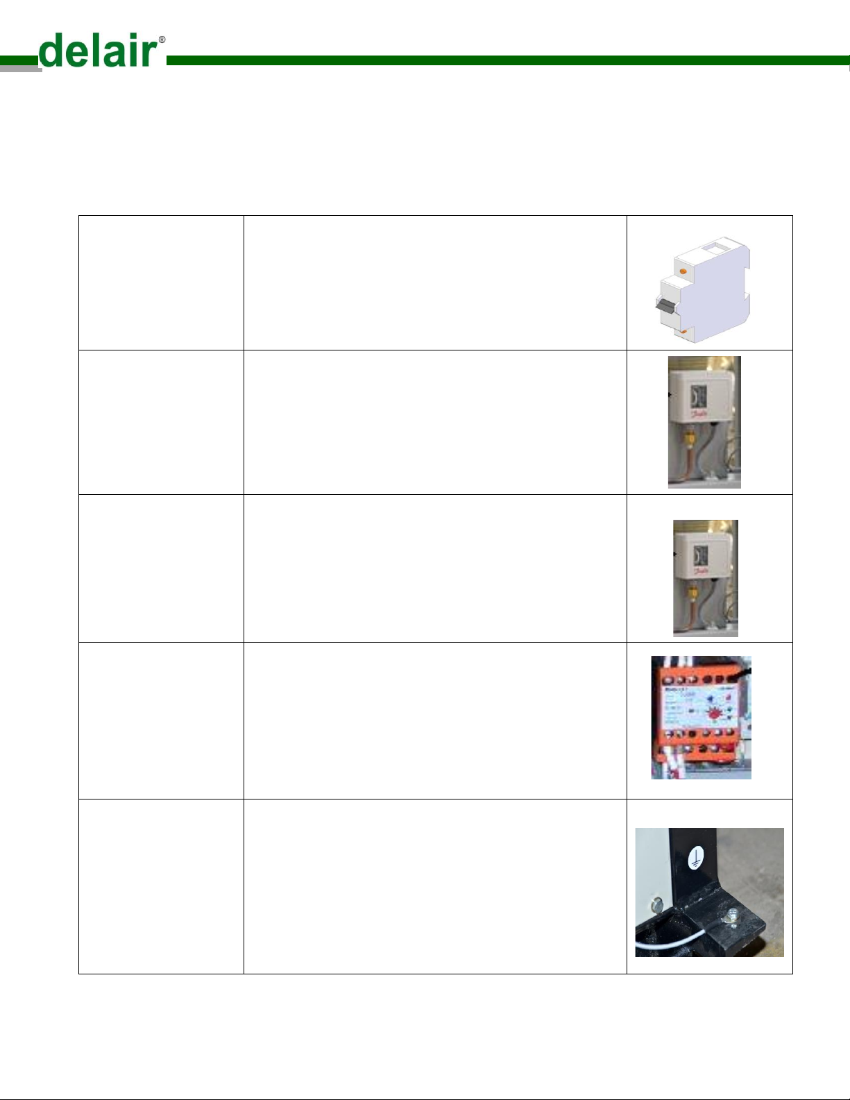
Miniature circuit breaker
( MCB )
MCB is located in the control panel box. It is help to protect
our Dryer unit against flow overcurrent.An Overcurrent
(insert MCB image) can be either an overload current or a
short circuit (insert MCB image)
High pressure control
switch
Pressure control switch is located in the field. In addition to
pressure control switches for refrigeration system have
pressure controls. Pressure control switch directly affect the
main mass flow of the refrigeration circuit by opening &
closing (insert pressure control switch image)
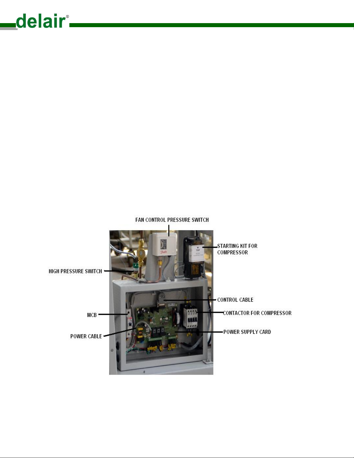
Fan control pressure
switch
Use on the high pressure side to a variable speed fan control
for ensuring that the condensing pressure does not drop too
low, especially in cold weather. (insert fan pressure control
switch image)
Single phase preventer
( motor protection relay )
( in case of 3 phase
supply unit )
Is located in the control panel box. It is help motor protection
in Following conditions :-
Overloading condition.
Phase failure condition.
Phase reversal condition
Unbalanced current condition
Dry running condition
(insert MPR image)
System earthing is essential to the proper operation of the
system, whereas equipment earthing concerns the safety of
personnel and plant. A key function of equipment earthing is
to provide a controlled method to prevent the build up of stat-
ic electricity, thus reducing the risk of electrical discharge in
potentially hazardous environments. Generally, a resistance
to earth of less than 10.6 ohms will ensure safe dissipation of
static electricity in all situations.