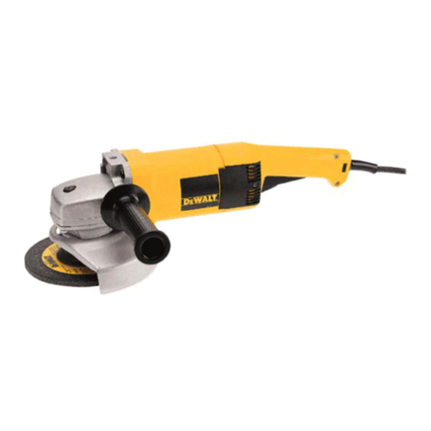
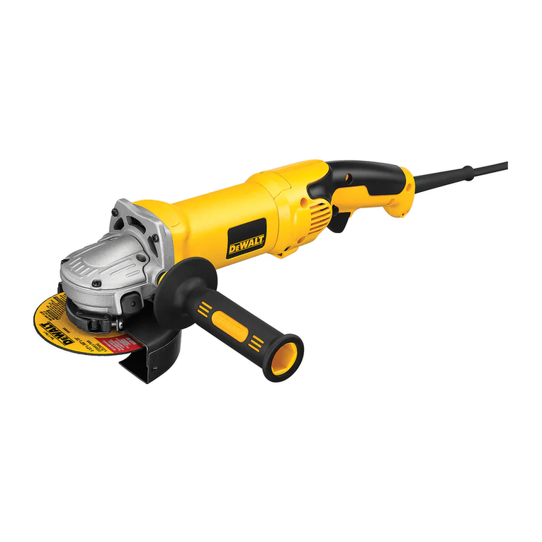
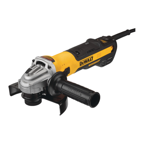
DeWalt DW831 User manual

Questions? See us on the World Wide Web at www.dewalt.com
INSTRUCTION MANUAL
GUIDE D'UTILISATION
MANUAL DE INSTRUCCIONES
INSTRUCTIVO DE OPERACION, CENTROS DE SERVICIO Y POLIZA
DE GARANT[A. ADVERTENCIA: LEASE ESTE INSTRUCTIVO
ANTES DE USAR EL PRODUCTO.
®
DW831, DW840
5" (125mm) and 7" (180mm) Heavy Duty Angle Grinder
Rectifieuse coudee de service intensif de 127 mm (5 po) et 175 mm (7 po)
Esmeriladora angular para trabajo pesado de 127 mm (5") y 175 mm (7")

IF YOU HAVE ANY QUESTIONS OR COMMENTS ABOUT THIS
OR ANY DEWALT TOOL, CALL US TOLL FREE AT:
1-800-4-DEWALT (1-800-433-9258)
General Safety Instructions
_WARNING! Read and understand all instructions.
Failure to follow all instructions listed below, may result
in electric shock, fire and/or serious personal injury.
SAVE THESE INSTRUCTIONS
WORK AREA
•Keep your work area clean and well lit. Cluttered benches
and dark areas invite accidents.
•Do not operate power tools in explosive atmospheres, such
as in the presence of flammable liquids, gases, or dust.
Power tools create sparks which may ignite the dust or fumes.
• Keep bystanders, children, and visitors away while operat-
ing a power tool Distractions can cause you to lose control
ELECTRICAL SAFETY
• Grounded tools must be plugged into an outlet properly
installed and grounded in accordance with all codes and
ordinances. Never remove the grounding prong or modify
the plug in any way. Do not use any adaptor plugs. Check
with a qualified electrician if you are in doubt as to whether
the outlet is properly grounded, ff the tools should electrical-
ly malfunction or break down, grounding provides a low resist-
ance path to carry electricity away from the user. Applicable
only to Class I (grounded) tools.
• Double insulated tools are equipped with a polarized plug
(one blade is wider than the other.) This plug will fit in a
polarized outlet only one way. ff the plug does not fit fully in
the outlet, reverse the plug. If #still does not fit, contact a
qualified electrician to install a polarized outlet. Do not
change the plug in any way. Double insu/ation [] e/iminates
the need for the three wire grounded power cord and grounded
power supply system. Applicable to Class II (double insu-
lated) tools.
Avoid body contact with grounded surfaces such as pipes,
radiators, ranges and refrigerators. There is an increased risk
of electric shock if your body is grounded.
Don't expose power tools to rain or wet conditions. Water
entering a power tool will increase the risk of electric shock.
Do not abuse the cord. Never use the cord to carry the tools
or pull the plug from an outlet. Keep cord away from heat,
oil, sharp edges or moving parts. Replace damaged cords
immediately. Damaged cords increase the risk of electric shock.
When operating a power tool outside, use an outdoor
extension cord marked "'W-A" or "'W." These cords are rated
for outdoor use and reduce the risk of electric shock. When
using an extension cord, be sure to use one heavy enough to
carry the current your product will draw. An undersized cord will
cause a drop in line voltage resulting in loss of power and over-
heating. The following table shows the correct size to use
depending on cord length and nameplate ampere rating, ff in
doubt, use the next heavier gage. The smaller the gage number,
the heavier the cord.
Minimum Gage for Cord Sets
Volts Total Length of Cord in Feet
120V 0-25 26-50 51-100 101-150
Ampere Rating
More Not more AWG
Than Than
12 16 14 12 Not Recommended

PERSONAL SAFETY
• Stay alert, watch what you are doing and use common
sense when operating a power tool Do not use tool while
tired or under the influence of drugs, alcohol, or medica-
tion. A moment of inattention while operating power tools may
result in serious personal injury.
• Dress properly. Do not wear loose clothing or jewelry.
Contain long hair. Keep your hair, clothing, and gloves
away from moving parts. Loose clothes, jewelrjL, or long hair
can be caught in moving parts. Air vents often cover moving
parts and should also be avoided.
•Avoid accidental starting. Be sure switch is off before plug-
ging in. Carrying tools with your finger on the switch or plugging
in tools that have the switch on invites accidents.
• Remove adjusting keys or wrenches before turning the tool
on. A wrench or a key that is left attached to a rotating part of
the tool may result in personal injury
•Do not overreach. Keep proper footing and balance at all
times. Proper footing and balance enables better control of the
tool in unexpected situations.
• Use safety equipment. Always wear eye protection. Dust
mask, non-skid safety shoes, hard hat, or hearing protec-
tion must be used for appropriate conditions.
TOOL USE AND CARE
•Use clamps or other practical way to secure and support
the workpiece to a stable platform. Holding the work by hand
or against your body is unstable and may lead to loss of control.
•Do not force tool Use the correct tool for your application.
The correct tool will do the job better and safer at the rate for
which #is designed.
•Do not use tool ff switch does not turn #on or off. Any tool
that cannot be controlled with the switch is dangerous and must
be repaired.
•Disconnect the plug from the power source before making
any adjustments, changing accessories, or storing the tooL
Such preventative safety measures reduce the risk of starting
the tool accidentally.
•Store idle tools out of reach of children and other untrained
persons. Tools are dangerous in the hands of untrained users.
•Maintain tools with care. Keep cutting tools sharp and
clean. Properly maintained tools, with sharp cutting edges are
less likely to bind and are easier to control
• Check for misalignment or binding of moving parts, break-
age of parts, and any other condition that may affect the
tools operation. If damaged, have the tool serviced before
using. Many accidents are caused by poorly maintained tools.
• Use only accessories that are recommended by the manu-
facturer for your model Accessories that may be suitable for
one tool may become hazardous when used on another tool
SERVICE
• Tool service must be performed only by qualified repair
personneL Service or maintenance performed by unqualified
personnel could result in a risk of injury
• When servicing a tool, use only identical replacement parts.
Follow instructions in the Maintenance section of this man-
ual Use of unauthorized parts or failure to follow maintenance
instructions may create a risk of electric shock or injury.
Additional Specific Safety Instructions
for Grinders
• Always use proper guard with grinding wheel. A guard pro-
tects operator from broken wheel fragments and wheel contact.
• Accessories must be rated for at least the speed recom-
mended on the tool warning label Wheels and other
accessories running over rated speed can fly apart and cause

injury.Accessoryratingsmustalwaysbeabovetoolspeedas
shownontoolnameplate.
•Hold tool by insulated gripping surfaces when performing
an operation where the cutting tool may contact hidden
wiring or its own cord. Contact with a "live" wire will make
exposed metal parts of the tool "live" and shock the operator.
•Do not use Type 11 Flaring Cup wheels on this tooL Using
inappropriate accessories can result in injury.
•Before using, inspect recommended accessory for cracks or
flaws. If such a crack or flaw is evident, discard the accessory
The accessory should also be inspected whenever you think the
tool may have been dropped. Flaws may cause wheel breakage.
•When starting the tool with a new or replacement wheel, a
new or replacement wire brush installed, or if you are
unsure of the condition of the wheel, hold the tool in a well
protected area and let it run for one minute, ff the wheel has
an undetected crack or flaw, it should burst in less than one
minute. If the wire brush has loose wires, they will be detected.
Never start the tool with a person in line with the wheel This
includes the operator.
•Avoid bouncing the wheel or giving #rough treatment. If this
occurs, stop the tool and inspect the wheel for cracks or flaws.
• Direct sparks away from operator, bystanders or flammable
materials. Sparks may be produced while using a sander or
grinder. Sparks may cause bums or start fires.
•Always use side handle. Tighten the handle securely. The
side handle should always be used to maintain control of the
tool at all times.
•Clean out your tool often, especially after heavy use. Dust
and grit containing metal particles often accumulate on interior
surfaces and could create an electric shock hazard.
• Do not operate this tool for long periods of time. Vibration
caused by tool action may be harmful to your hands and arms.
Use gloves to provide extra cushion and limit exposure by taking
frequent rest periods.
WARNING: Some dust created by power sanding, sawing, grind-
ing, drilling, and other construction activities contains chemicals
known to cause cancer, birth defects or other reproductive harm.
Some examples of these chemicals are:
•lead from lead-based paints,
•crystalline silica from bricks and cement and other masonry
products, and
•arsenic and chromium from chemically-treated lumber
(CCA).
Your risk from these exposures varies, depending on how often you
do this type of work. Toreduce your exposure to these chemicals:
work in a well ventilated area, and work with approved safety equip-
ment, such as those dust masks that are specially designed to fil-
ter out microscopic particles.
• Avoid prolonged contact with dust from power sanding,
sawing, grinding, drilling, and other construction activi-
ties. Wear protective clothing and wash exposed areas with
soap and water. Allowing dust to get into your mouth, eyes, or
lay on the skin may promote absorption of harmful chemicals.
AWARNING: Use of this tool can generate and/or disburse dust,
which may cause serious and permanent respiratory or other injury
Always use NIOSH/OSHA approved respiratory protection appro-
priate for the dust exposure. Direct particles away from face and
body.
_CAUTION: Use extra care when grinding into a corner
because a sudden, sharp movement of the grinder may be experi-
enced when the wheel or other accessory contacts a secondary
surface.
CAUTION: Wear appropriate hearing protection during use.
Under some conditions and duration of use, noise from this prod-
uct may contribute to hearing loss.


Thelabelonyourtoolmayincludethefollowingsymbols.The
symbolsandtheirdefinitionsareasfollows:
V.......... volts A .......... amperes
Hz ............ hertz
min .......... minutes
........ direct current
[] .............. Class II Construction
_ .............. earthing terminal
INTRODUCTION
COMPONENTS
A. Trigger Switch
B. Lock-On Button
C. Spindle Lock Button
W.......... watts
"_ .......... alternating current
no .......... no load speed
.......... safety alert symbol
.../min ....revolutions per
minute
D. Side Handle
E. Guard (Type 27, open
beneath wheel or
accessory)
ASSEMBLY
_CAUTION: Turn off and unplug the tool before making any
adjustments or removing or installing attachments or acces-
sories. Before reconnecting the tool, depress and release the
rear part of the switch to ensure that the tool is off.
ATTACHING SIDE HANDLE
The side handle can be fitted to either side of the gear
case in the threaded holes, as shown. Before using the
tool, check that the handle is tightened securely.
ACCESSORIES
It is important to choose the correct guards, backing
pads and flanges to use with grinder accessories. See
pages 5-6 for information on choosing the correct
accessories.
_},CAUTION: Accessories must be rated for at least the speed
recommended on the tool warning label Wheels and other acces-
sories running over their rated speed may fly apart and cause
injury. Threaded accessories must have a 5/8" -11 hub. Every
unthreaded accessory must have a 7/8" arbor hole. ff it does not, it
may have been designed for a circular saw. Use only the acces-
sories shown on pages 5-6 of this manual Accessory ratings must
always be above listed tool speed as shown on tool nameplate.
OPERATION
Switch
i_ CAUTION: Check that the tool is not locked ON before connect-
ing it to a power supply, ff the trigger switch is locked ON when the
tool is connected to the power supply, it will start immediately.
Damage to your tool or personal injury may result.
To start the tool, squeeze the trigger switch (A). To turn the tool off,
release the switch. The tool can be locked on for continuous use by
holding the trigger switch depressed while you depress the switch
locking button next to the trigger. Hold the lock-on button (B) in as
you gently release the trigger. Release the locking button and the
tool will continue to run. To turn the tool off from a locked on condi-
tion, squeeze and release the trigger once.

5" Grinding Wheels (DW831) 7" Grinding Wheels (DW840)
Type 27 guard
unthreaded backing flange
Type 27 depressed center wheel
threaded clamp nut
Type 27 guard
backing flange
Type 27 non-hubbed wheel
clamp nut
Type 27 guard
Type 27 hubbed wheel
Type 27 guard
Type 27 hubbed wheel

Wire Wheels Sanding Flap Discs Sanding Discs (DW831)
Type 27 guard
3" wire cup brush
Type 27 guard
4" wire wheel
Type 27 guard
unthreaded backing flange
non-hubbed sanding flap disc
threaded clamp nut
Type 27 guard
hubbed sanding flap disc
rubber backing pad
sanding disc
threaded clamp nut
.& WARNING: DW840 cannot be
used with conventional sanding
discs and backing pads due to
mismatched rated speeds.
_CAUTION: Use a Type 27 guard with wire brushes and
wheels. Operators and others in the area should wear appropriate
eye, face and body protection. Strands of wire may break and fly
off when wire wheels and brushes are in use.

Grinding
Using a depressed center Type 27 wheel,
hold the tool at an angle of approximately
10°- 30° to the work for grinding. Most
Type 27 wheels are not designed for cut-
ting operations.
Edge Cutting
10° _ 30°
_, WARNING: Edge grinding and cutting can be performed only with
Type 27 wheels that are designed and specified for this purpose.
Protect yourseff during edge cutting by directing the open side of
the guard toward a surface.
i_ WARNING: Wheels used for cutting and edge grinding may
break or kick back ff they bend or twist while the tool is being used
to do cut-off work or deep grinding. To reduce the risk of serious
injury, lim# the use of these wheels with a standard Type 27 guard
to shallow cutting and notching (less than 1/2" in depth). The open
side of the guard must be positioned away from the operator.
1. Allow the tool to reach full speed before touching the tool to the
work surface.
2. Apply minimum pressure to the work surface, allowing the
tool to operate at high speed. Grinding
rate is greatest when the tool operates
at high speed.
3. Position yourself so that the open-
underside of the wheel is facing away
from you.
4. Once a cut is begun and a notch is
established in the workpiece, do not
change the angle of the cut. Changing
the angle will cause the wheel to bend
and may cause wheel breakage.
5. Remove the tool from the work surface before turning the tool
off. Allow the tool to stop rotating before laying it down.
Edge grinding and cutting wheels should contact the work surface
only at the edge of the wheel, not on the top or bottom ofthe wheel.
Side pressure on the wheel could lead to breakage of the wheel.
_WARNING: Do not use edge grinding/cutting wheels for surface
grinding applications because these wheels are not designed for
side pressures encountered with surface grinding. Wheel breakage
and injury may result.
Sanding With Abrasive Discs
When using an abrasive disc and rubber backing pad, hold the tool
so that an angle of 10° to 15° exists between the disc and the
work, as shown. Using an angle of 5°to 15°
will allow you to produce a smooth surface.
If only the outer edge of the sanding disc is
pressed flat against the work, the sanding
action will be irregular and bumpy, and the 1s°
tool will be difficult to control.
Precautions To Take When
Removing Paint
1. Sanding or wire brushing lead based paint is NOT RECOM-
MENDED due to the difficulty of controlling the contaminated
dust. The greatest danger of lead poisoning is to children and
pregnant women.
2. Since it is difficult to identify whether or not a paint contains lead
without a chemical analysis, we recommend the following pre-
cautions when sanding any paint:
PERSONAL SAFETY
1. No children or pregnant women should enter the work area
where the paint sanding is being done until all clean up is
completed.

2.Adustmaskorrespiratorshouldbewornbyallpersonsenter-
ingtheworkarea.Thefiltershouldbereplaceddailyorwhen-
everthewearerhasdifficultybreathing.
NOTE:Onlythosedustmaskssuitableforworkingwithlead
paintdustandfumesshouldbeused.Ordinarypaintingmasks
donotofferthisprotection.Seeyourlocalhardwaredealerfor
theproperN.I.O.S.H.approvedmask.
3.NOEATING,DRINKINGorSMOKINGshouldbedoneinthe
workareatopreventingestingcontaminatedpaintparticles.
WorkersshouldwashandcleanupBEFOREeating,drinking
orsmoking.Articlesoffood,drink,orsmokingshouldnotbeleft
intheworkareawheredustwouldsettleonthem.
ENVIRONMENTALSAFETY
1.Paintshouldberemovedinsuchamannerastominimizethe
amountofdustgenerated.
2.Areaswherepaintremovalisoccurringshouldbesealedwith
plasticsheetingof4milsthickness.
3.Sandingshouldbedoneinamannertoreducetrackingofpaint
dustoutsidetheworkarea.
CLEANINGANDDISPOSAL
1.Allsurfacesintheworkareashouldbevacuumedandthor-
oughlycleaneddailyforthedurationofthesandingproject.
Vacuumfilterbagsshouldbechangedfrequently.
2.Plasticdropclothsshouldbegatheredupanddisposedof
alongwithanydustchipsorotherremovaldebris.Theyshould
beplacedinsealedrefusereceptaclesanddisposedofthrough
regulartrashpick-upprocedures.
Duringcleanup,childrenandpregnantwomenshouldbekept
awayfromtheimmediateworkarea.
3.Alltoys,washablefurnitureandutensilsusedbychildren
shouldbewashedthoroughlybeforebeingusedagain.
FIG. 1 FIG. 2
Fitting and Removing the Guard DW831
(Fig. 1 & 2)
ACAUTION: Unplug the tool before mounting or removing the
guard. Guards must be used with aft grinding wheels and sanding
flap discs, wire brushes and wire wheels. The tool may be used
without the guard only when sanding with conventional sanding
discs. Before reconnecting the tool, depress and release the rear
part of the switch to ensure that the tool is off.
FITTING GUARD
_CAUTION: Do not operate grinder with a loose guard or the
guard latch in the open position.
1. Open the guard latch (A) and align the arrow on the guard with
the arrow on the gear case.
2. Push the guard down until the guard lugs engage and rotate
freely in the groove on the gear case.
3. With the guard latch open, rotate the guard into the working
position providing maximum protection to the user (Fig. 2).
4. Close the guard latch to secure guard on gear case (Fig. 2).
NOTE: The guard is pre-adjusted to the diameter of the spindle hub
at the factory. If the guard needs further adjustment after a period of

use,performthefollowingadjustment.Withtheguardlatchinthe
closedpositiontightenorloosentheadjustmentscrew(Fig.2B).
REMOVINGGUARD
1.Opentheguardlatch(A)andalignthearrowontheguardwith
thearrowonthegearcase.
2.Pulltheguardupuntiltheguardlugsengageandrotatefreely
inthegrooveonthegearcase.
3.Withtheguardlatchopen,rotatetheguarduntilthearrowsare
aligned.(Fig.2).
4.Removetheguard.
_CAUTION:Do not tighten adjusting screw with guard latch in
open position. Undetectable damage to the guard or the mount-
ing hub may result.
Fitting and Removing the Guard DW840
(Fig. 3)
_CAUTION: Unplug the tool before mounting or removing the
guard. Guards must be used with all grinding wheels and sand-
ing flap discs, wire brushes and wire wheels. The tool may be
used without the guard only when sanding with conventional
sanding discs. Before reconnecting the tool, depress and release
the rear part of the switch to ensure that the tool is off.
FITTING GUARD
_,CAUTION: Do not operate grinder with a loose FIG. 3
guard or the guard latch in the open position.
1. Place the angle grinder on a table, spindle up.
2. Press the guard down.
3. Position the guard between your body and
the work piece.
4. Tighten the screw holding the cinch collar
firmly around the neck of the spindle.
REMOVING GUARD
1. Loosen the screw holding the cinch collar around the neck of
the spindle.
2. Lift up on the guard.
ACAUTION: Do not tighten adjusting screw with guard latch in
open position. Undetectable damage to the guard or the mount-
ing hub may result.
Fitting a Backing Pad and Sanding Disc
Backing pads are available as optional accessories. To fit the pad,
follow instructions provided with the accessory.
CAUTION: Proper guard must be re-installed for grinding wheel
applications after sanding applications are complete.
J_CAUTION: Accessories must be rated for at least the speed
recommended on the tool warning label Wheels and other acces-
sories running over rated speed can fly apart and cause injury.
Accessory ratings must always be above tool speed as shown on
tool nameplate.
Mounting Grinding Wheels (Fig. 4-7)
Grinding wheels are available as optional accessories.
1. Place the backing flange on the grinder spindle (Fig. 4).
2. Place the wheel against the flange, centering the grinding
wheel on the backing flange pilot.
FIG. 4 FIG. 5 FIG. 6

3. Screw the threaded flange onto the
spindle (Fig. 5).
4. Rotate the spindle by hand while press-
ing the spindle lock button (Fig. 6) until
the spindle locks, preventing the spin-
dle from rotating.
5. Securelytighten the threaded flange with FIG.7
the supplied spanner wrench (Fig. 7).
Fitting Wire Cup Brushes
The wire cup brush screws directly on the spindle of the machine
without the use of flanges. AType 27 guard is required when using
wire brushes or wheels.
CAUTION: Wear work gloves when handling wire cup brushes.
Wire brushes can become sharp.
MAINTENANCE
Cleaning
_, WARNING: Blow dust and grit out of the motor housing regularly
using clean, dry compressed air. Dust and grit containing metal
particles often accumulate on interior surfaces and could create an
electrical shock hazard if not frequently cleaned out. ALWAYS
WEAR SAFETY GLASSES.
_,CAUTION: Never use solvents or other harsh chemicals for
cleaning the non-metallic parts of the tooL These chemicals may
weaken the plastic materials used in these parts. Use a cloth damp-
ened only with water and mild soap.
Lubrication
DEWALT tools are properly lubricated at the factory and are ready
for use. Tools should be relubricated regularly every sixty days to six
months, depending on usage. (Tools used constantly on production
or heaw-duty jobs and tools exposed to heat may require more 10
frequent lubrication.) This lubrication should only be attempted by
trained power tool repair persons, such as those at DEWALT serv-
ice centers or by other qualified service personnel.
Motor Brushes
When brushes become worn, the tool will automatically stop and
prevent damage to the motor. Brush replacement should be per-
formed by DEWALT authorized service centers.
Accessories
Recommended accessories for use with your tool are available at
extra cost from your local dealer or authorized service center. If you
need assistance in locating any accessory for your tool, contact:
DEWALT Industrial Tool Co., 701 East Joppa Road, Baltimore, MD
21286.
,Z_,CAUTION: Accessories must be rated for at least the speed
recommended on the tool warning label Wheels and other acces-
sories running over rated speed can fly apart and cause injury.
Accessory ratings must always be above tool speed as shown on
tool nameplate.
ACAUTION: The use of any other accessory not recommended
for use with this tool could be hazardous.
Repairs
To assure product SAFETY and RELIABILITY, repairs, mainte-
nance and adjustment should be performed by authorized service
centers or other qualified service personnel. Always use identical
replacement parts.
Three Year Limited Warranty
DEWALT will repair, without charge, any defects due to faulty mate-
rials or workmanship for three years from the date of purchase.
This warranty does not cover part failure due to normal wear or tool

abuse.Forfurtherdetailofwarrantycoverageandwarrantyrepair
information,visitwww.dewalt.comorcall1-800-4-DEWALT(1-800-
433-9258).Thiswarrantydoesnotapplytoaccessoriesordamage
causedwhererepairshavebeenmadeorattemptedbyothers.
Thiswarrantygivesyouspecificlegalrightsandyoumayhave
otherrightswhichvaryincertainstatesorprovinces.
Inadditiontothewarranty,DEWALTtoolsarecoveredbyour:
1YEARFREESERVICE
DEWALTwillmaintainthetoolandreplacewornpartscausedby
normaluse,forfree,anytimeduringthefirstyearafterpurchase.
90 DAY MONEY BACK GUARANTEE
If you are not completely satisfied with the performance of your
DEWALT Power Tool, Laser, or Nailer for any reason, you can
return it within 90 days from the date of purchase with a receipt for
a full refund - no questions asked.
FREE WARNING LABEL REPLACEMENT: If your warning labels
become illegible or are missing, call 1-800-4-DEWALT for a free
replacement.
11

POURTOUTEQUESTIONOUREMARQUEAUSUJETDECET
OUTILOUDETOUTAUTREOUTILDEWALT,COMPOSERLE
NUMC:ROSANSFRAIS•18004-DEWALT(1800433-9258)
Directives de s_curit_ d'ordre g_n_ral
AVERTISSEMENT! S'assurer de fire et de bien com-
prendre toutes les directives. Le non-respect des
directives decrites ci-apr#s pourrait #tre la cause de chocs
electriques, d'incendies et/ou de blessures graves.
CONSERVER CES DIRECTIVES
AIRE DE TRAVAIL
•L'aire de travail doff 6tre propre et bien eclairee. Les 6tablis
encombr6s et le manque de lumiere peuvent entrainer des
accidents.
•Ne pas faire fonctionner des outils electriques clans des
atmospheres explosives, comme en presence de liquides,
de gaz et de poussieres inflammables. Les outils 6/ectriques
produisent des 6tincelles qui peuvent enflammer la poussiere
ou les vapeurs.
• Tenir les spectateurs, les enfants et les visiteurs a I'ecart
Iorsqu'on utilise I'outil. Les distractions peuvent entrainer une
perte de maitrise.
REGLES DE SI_CURITI_ RELATIVES _, L'I_LECTRICITI_
•Les outils mis a la terre doivent 6tre branches clans une
prise correctement installee et raise a la terre tel que
I'indiquent les codes et reglements en vigueur. Ne jamais
retirer la broche de raise a la terre ou modifier la prise en
aucune fagon. Ne pas utiliser de fiche d'adaptation.
Consulter un electricien qualifie s'il y aun doute en ce qui
concerne la mise ala terre de la prise. En cas de mauvais
fonctionnement ou de bris des outils, la mise a la terre offre un 12
chemin de faible r6sistance afin d'emp#cher 1'61ectrocution de
I'utilisateur. S'applique uniquement aux outils de classe I
(mis a la terre).
• Les outils a double isolation sont pourvus d'une fiche
polarisee (une lame est plus large que I'autre). Cette fiche
ne peut 6tre branchee clans une prise polarisee que clans
un seul sen& Si la fiche ne peut 6tre branchee clans la prise,
inverser la fiche. Si on n'arrive pas a la brancher, commu-
niquer avec un electricien qualifie afin qu'il installe une
prise polarisee. Ne pas modifier la fiche. La double isolation
61imine le besoin du systeme de rallonge d'alimentation
trois ills et de bloc d'alimentation avec mise a la terre.
S'applique uniquement aux outils de classe II (a double iso-
lation).
• Eviter tout contact corporel avec des surfaces mises a la
terre, comme des tuyaux, des radiateurs, des cuisinieres et
des refrigerateurs. Le risque de choc 61ectrique augmente si le
corps est mis a la terre.
•Ne pas exposer les outils electriques a la pluie ou aI'eau.
L'infiltration d'eau clans un outi161ectrique augmente le risque de
choc 61ectrique.
• Manipuler le cordon avec soin. Ne jamais s'en servir pour
transporter I'outil ou pour tirer la fiche hors de la prise. Tenir
le cordon a 1'6cart de la chaleur, de I'huile, des ar6tes vives ou
des pieces mobiles. Remplacer imm#diatement les cordons
endommag#s, car ils augmentent le risque de choc #lectrique.
•Lorsqu'on utilise un outil electrique a I'exterieur, il faut
employer une rallonge portant I'inscription "'W-A" ou "'W."
Ces rallonges sont congues pour I'utilisation a I'ext_rieur et
r#duisent le risque de choc #lectrique. S'il y a lieu d'utiliser une
rallonge, s'assurer que celle-ci est de calibre suffisamment #lev#
pour acheminer le courant n#cessaire au fonctionnement de
Ibutil. Une rallonge de calibre trop faible pourra# causer une chute

detensionsetraduisantparunepertedecourantetune
surchauffe.Letableauquisuitindiquelecalibreappropri6selon
laIongueurdelarallongeetI'intensit6indiqu6esurlaplaque
signal6tique.Encasdedoute,utiliserlecalibresup6rieursuivant.
Pluslenum6rodecalibreestpetit,pluslecalibredelarallonge
est61ev6.Calibre minimal des cordons de rallonge
Tension Longueur totale du cordon en m_tres
120V De0&7 De7&15 De15&30 De 30&45
Intensit6 (A)
Au Au Calibre moyen de fil
moins plus
12 16 14 12 Non recommand6
SC'CURIT¢' PERSONNELLE
*Demeurer alerte, pr6ter attention ace que I'on fait et faire
preuve de bons sens Iorsqu'on utilise un outil electrique.
Ne pas utiliser un outil Iorsqu'on ressent de la fatigue ou
apres avoir consomme des drogues, de I'alcool, ou des
medicaments. Un moment d'inattention durant I'utilisation
dbutils 61ectriques peut entrMner de graves blessures.
,Porter des v6tements appropries. Ne pas porter des v6te-
ments amples ou des bijoux. Les cheveux longs doivent
6tre retenus. Tenir les cheveux, les v6tements et les gants
I'ecart des pieces mobiles. Les v_tements amples, les bijoux
et les cheveux longs peuvent 6tre happ6s par des pieces
mobiles. IIfaut 6galement se tenir a 1'6cart des 6vents qui recou-
vrent souvent les pieces mobiles.
, Eviter le demarrage accidenteL S'assurer que I'interrupteur
est en position d'arr6t avant de brancher I'outil. Le fait de
transporter un outil en appuyant sur la g&chette ou de le branch-
er Iorsque I'interrupteur se trouve en position de marche peut
causer des accidents.
•Deposer les cles de reglage ou de serrage avant de mettre
I'outil en marche. Une cl6 laiss6e fix6e a une piece rotative de
I'outil peut entrafner des blessures.
• Ne pas tendre le bras trop loin. II faut demeurer en equilibre
en tout temps. Un bon 6quilibre permet une meilleure mMtrise
de I'outil dans les situations inattendues.
•Utiliser du materiel de securite. Toujours porter des
lunettes de protection. I/ faut uti/iser, au besoin, un masque
antipoussieres, des chaussures de s6curit6 antid6rapantes, un
casque de s6curit6 ou des protecteurs d'oreilles.
UTILISATION DES OUTILS ET PRleOAUTIONS
• Utiliser des pinces ou un autre moyen pratique de fixer et
de soutenir la piece a travailler sur une plateforme stable.
Le fait de tenir la piece avec la main ou de I'appuyer contre le
corps ne permet pas de la stabiliser et cela risque de causer une
perte de mMtrise.
•Ne pas forcer I'outil. Utiliser celui qui convient au travail
effectuer. Lbutil ad6quat permet de faire le travail de fa_on plus
convenable et sore Iorsqu'il est employ6 suivant I'utilisation pour
laquelle il a6t6 congu.
• Ne pas utiliser I'outil si I'interrupteur ne permet pas de le
mettre sous ou hors tension. Tout outil impossible a com-
mander au moyen de I'interrupteur est dangereux et doit 6tre
r6par6.
•Debrancher la fiche de la source d'alimentation avant d'ef-
fectuer des reglages, de changer d'accessoire ou de ranger
I'outil. De telles mesures pr6ventives r6duisent le risque de le
mettre en marche accidentellement.
• Ranger les outils hors de la portee des enfants et des
autres personnes non qualifiees. Les outils sont dangereux
entre les mains d'utilisateurs non qualifi6s.
13

• Veiller aentretenir correctement les outils. Les accessoires
de coupe doivent 6tre maintenus bien affOtes et propres.
Des outils bien entretenus, et dont les ar6tes sont coupantes,
sont moins susceptibles de se coincer et sont plus faciles
manier.
•Verifier la presence de pieces mobiles mal alignees ou
coincees, de pieces brisees ou de toute autre condition
pouvant alterer le fonctionnement de I'outil. Si I'outil est
endommage, il faut le faire reparer avant de I'utiliser. De
nombreux accidents sont caus6s par des outils mal entretenus.
•Utiliser seulement des accessoires recommandes par le
fabricant du modele. Des accessoires convenant a un outil
peuvent 6tre dangereux Iorsqu'on les installe sur un autre outil.
R#PARATION
•Seules des personnes qualifiees peuvent reparer les outils.
Une r6paration ou un entretien effectu6 par une personne non
qualifi6e risque d'entraTner des blessures.
•II faut utiliser uniquement des pieces de rechange iden-
tiques pour reparer un outil. Suivre les directives figurant
clans la section Entretien du present manuel. L'emp/oi de
pieces inad6quates ou le non-respect des directives d'entretien
peut provoquer un choc 61ectrique ou des blessures.
Consignes de sdcuritd particulidres
relatives aux rectifieuses
•Utiliser toujours le protecteur convenant ala meule. Ilprotege
I'utilisateur contre les projections de fragments en cas de bris et
emp6che tout contact avec la meule.
• Lesaccessoiresdoivent6treconFusaumoinspourleregime
recommande sur I'etiquette d'avertissement de I'outil. Les
meules et autres accessoires toumant a un r6gime sup6rieur a la
14
vitesse nominale peuvent se d6sint6grer et causer des blessures.
La vitesse nominale de I'accessoire doit toujours 6tre sup6rieure
celle de Ibutil indiqu6e sur la plaque signal6tique de Ibutil.
• Tenir I'outilpar les surfaces de saisie isolees au cours d'une
operation oO I'accessoire de coupe risque d'entrer en
contact avec des ills dissimules ou le cordon de I'outil. Tout
contact avec un fil "sous tension "provoquera "l'61ectrisation "des
parties m6talliques expos6es et 1'61ectrocution de I'utilisateur.
• Ne pas utiliser des meules de type 11 (meules boisseaux
coniques) sur cet outil. L'utilisation d'accessoires non
appropri6s pourrait causer des blessures.
• Avant d'utiliser les accessoires recommandes, s'assurer
qu'ils ne presentent aucune fissure ou defectuosite. $i une
fissure ou defectuosite est evidente, mettre I'accessoire au
rebut, fl faut egalement verifier I'accessoire si I'on soupFonne
que I'outil a subi une chute. Un accessoire d6fectueux pourrait
entraTnerle bris de la meule.
• Lorsqu'on demarre I'outil apres y avoir installe une meule,
une brosse metallique, neuve ou de rechange, ou si I'etat de
marche de la meule est douteux, tenir I'outil clans un endroit
bien protege et le faire fonctionner pendant une minute. Si la
meule comporte une fissure ou une d6fectuosit6 non d6tect6e, elle
devrait se d6sint6grer en moins d'une minute. S'il y a des ills
I&ches clans la brosse m6tallique, ils seront d6tect6s. A!ejamais
mettre I'outil en marche Iorsqu'une personne est plac#e dans I'axe
de la meule. Cette mesure s'applique #galement a I'utilisateur.
• Eviter de faire rebondir la meule ou de I'utiliser de faFon
abusive. Si cela se produit, arr6ter I'outil et v#rifier s'il y a
presence de fissure ou de d#fectuosit#.
• Orienter les etincelles clans la direction opposee
I'utilisateur et aux autres personnes presentes ou de tout
materiau inflammable. L'utilisation d'une meuleuse ou d'une

ponceusepeutproduiredes6tincelles qui risquent de causer des
brOlures ou des incendies.
• Utiliser toujours la poignee laterale et la serrer solidement.
II faut toujours se servir de la poign6e lat6rale pour maTtriser
Ibutil en tout temps.
• Nettoyer I'outil frequemment, plus particulierement s'il est
soumis a une utilisation intensive. De la poussiere contenant
des particules m6talliques s'accumule souvent sur les surfaces
int6rieures et pourrait provoquer un choc 61ectrique.
• Ne pas utiliser cet outil pendant des periodes prolongees.
Les vibrations caus6es par I'outil peuvent poser des risques pour
les mains ou les bras. Porter des gants pour amortir les vibra-
tion& et pour limiter les risques faire des pauses fr6quentes.
_AVERTISSEMENT :Certaines poussieres cr66es par le
pongage, le sciage, le meulage et le forage m6canique ainsi que
d'autres activit6s de construction contiennent des produits chim-
iques susceptibles de causer le cancer, des anomalies cong6ni-
tales ou d'autres anomalies li6es a la reproduction. Parmi ces
produits chimiques, citons notamment :
•le plomb provenant des peintures au plomb;
•la silice cristalline provenant des briques, du b6ton et d'autres
mat6riaux de magonnerie;
•I'arsenic et le chrome provenant du bois trait6 (ars6niate de
cuivre et de chrome).
Le risque associ6 a ces expositions varie selon la fr6quence de ces
types de travaux. Pour r6duire I'exposition aux produits chimiques :
travailler dans un local bien ventil6 et utiliser du mat6riel de s6curit6
approuv6, comme les masques anti-poussieres sp6cialement
congus pour filtrer les particules microscopiques.
•Eviter le contact prolonge avec la poussiere provenant du
pon¢age, du sciage, du meulage et du forage mecanique
ainsi que d'autres activites de construction. Porter des
v6tements de protection et laver les parties exposees au
savon eta I'eau. La poussiere qui pourrait p6n6trer clans la
beuche et les yeux eu se d6peser sur la peau peut faveriser
I'absorption de preduits chimiques nocifs.
i_AVERTISSEMENT :Teute personne entrant la zone de travail
devrait porter un masque anti-poussieres ou un appareil respira-
teire. Le filtre doit en 6tre remplac6 quotidiennement ou chaque feis
que I'utilisateur commence a aveir des difficult6s a respirer. Se ren-
seigner aupres de son quincaillier local pour la liste des masques
anti-poussieres appreuv6s par le NIOSH/OSHA.
AMISE EN GARDE :Le meulage a I'interieur d'un angle ou
clans un coin peut cr6er un mouvement brusque de I'outil si la
meule eu un autre accessoire touche a une surface secondaire
eu a teute autre surface. II faut denc 6tre tres vigilant.
AMISE EN GARDE :Porter des protecteurs d'oreilles appro-
pries durant I'utilisation. Selen les conditions et la dur6e d'utili-
satien, le bruit 6mis par cet eutil peut causer une perte auditive.
•L'6tiquette appos6e sur I'eutil peut comprendre les symboles
suivants. Veici les symbeles et leurs d6finitions :
V.......... volts A .......... amperes
Hz ........hertz W.......... watts
min ......minutes '%, ........courant altematif
.... ....courant direct
[] ........construction
de classe II
0 ........borne de mise
la terre
no ........r6gime sans charge
.../min ..tours ou va-et-vient
par minute
_ .......... symbole d'alerte
relatifs a la s6curit6
15

INTRODUCTION
COMPOSANTS
A. Interrupteur & g&chette
B. Bouton de verrouillage
en position de marche
C. Bouton de verrouillage
de la broche
D. Poign6e lat6rale
E. Dispositif de protection
(Type 27, ouvert sous
la meule ou I'accessoire)
ASSEMBLAGE
_MISE EN GARDE : Arr6ter eL debrancher I'outil avant tout
reglage ou avant de retirer ou installer toute piece ou acces-
soire. A vant de rebrancher I'outil, appuyer puis rel&cher la par-
tie arriere de I'interrupteur pour vous assurer que I'outil est
bien aI'arr6L
FIXATION DE LA POIGNI_E tAT#RAtE
La poign6e lat6rale, comme illustr6, peut 6tre instal-
16esur run ou I'autre c6t6 du carter d'engrenage dans
les orifices filet6s. Avant utilisation de I'outil, v6rifier
que la poign6e est solidement arrim6e.
ACCESSOIRES
II est important de choisir les 6crans protecteurs,
plateaux porte-disque et brides qui conviennent aux
accessoires de meulage. Voir les pages 18 et 19 pour obtenir plus
de renseignements quant aux accessoires appropri6s.
AMISE EN GARDE : Les accessoires doivent 6tre congus au
moins pour le r6gime recommand6 sur 1'6tiquette d'avertissement
de I'outil. Les meules et autres accessoires toumant a un r6gime
sup6rieur a la vitesse nominale des accessoires peuvent se d6sin-
t6grer et causer des blessures. Les accessoires filet6s doivent #tre
mont6s sur un moyeu de 5/8 po -11. Tousles accessoires non
filet6s doivent avoir un orifice d'arbre de 7/8 po. Si ce n'est pas le
cas, il est possible qu'ils aient 6t6 congus pour une scie circulaire.
Utiliser uniquement les accessoires illustr6s aux pages 18 et 19 du
pr6sent manuel Le r6gime nominal des accessoires doit toujours
6tre sup6rieur a la vitesse minimale de I'outil, telle qu'indiqu6e sur
la plaque signal6tique de I'outiL
FONCTIONNEMENT
Interrupteur
_&MISE EN GARDE : S'assurer que Ibutil n'est pas verrouill6 en
position de MARCHE avant de le brancher. Si I'interrupteur est ver-
rouill6 en position de MARCHE /ors du branchement, I'outil d6mar-
rera automatiquement. Cela pose des risques pour I'outil et pour
vous m6me.
Pour mettre I'outil en marche, appuyer sur I'interrupteur & g&chette
(A). Pour arr6ter I'outil, rel&cher I'interrupteur. L'outil peut _tre ver-
rouill6 en position de marche pour une utilisation continue en main-
tenant I'interrupteur enfonc6 tout en appuyant sur le bouton de ver-
rouillage situ6 & c6t6 de I'interrupteur. Maintenir ce bouton de ver-
rouillage en position de marche (B) enfonc6 puis rel&cher lente-
ment I'interrupteur. Rel&cher le bouton de verrouillage et I'outil
marchera en continu. Pour arr6ter I'outil Iorsqu'il est verrouill6 en
position de marche, appuyer puis rel&cher une fois sur I'interrup-
teur.
16

Meules de 5 po (DW831) Meules de 7 po (DW840)
Protecteur de type 27
Bride de support non filet_e
Meule & moyeu d_port_ de type 27
€:crou de bride filet_e
Protecteur de type 27
Bride de soutien
Meule sans moyeu de type 27
€:crou de blocage
Protecteur de type 27
Meule & moyeu de type 27
17
Protecteur de type 27
Meule & moyeu de type 27

Brosses
m_talliques
circulaires
Protecteur de type 27
Brosse forme
coupelle de 3 po
Protecteur de type 27
Meule m6tallique
de 4 po
Disques souples de pon_age
Protecteur de type 27
Bride de support non filet6e
Disque souple de pon£_age
sans moyeu
12croude blocage filet6
Protecteur de type 27
Disque de pon£age & moyeu
MISE EN GARDE : Utiliser un dispositif de protection de type
27 avec les brosses metalliques circulaires ou autres. // est
recommand6 que I'utilisateur ou toute autre personne pr6sente porte
un dispositif appropri6 de protection oculaire, facial et corporeL Des
fragments m6talliques risquent de se d6tacher et s'envoler pendant
I'utilisation de brosses m6talliques.
18
Disques de pon_age
(DW831)
Plateau porte-disque
en caoutchouc
Disque de pon£age
12croude bride filet6e
_&AVERTISSEMENT :La DW840
ne peut _tre utilis6e avec des
disques abrasifs et tampons
de soutien conventionnels
cause d'une disparit6 de vitesse
nominale.

Meulage
Utiliser une meule & moyeu d6port6 de
type 27. Maintenir I'outil &un angle approx-
imatif de 10°- 30° de la piece & meuler. La
plupart des meules de type 27 ne sont pas
con_ues pour des op6rations de coupe.
Coupe de Bord
10°-30 °
AAVERTISSEMENT :Le meulage et la coupe de bord ne doivent
#tre ex6cut6s qu'avec une meule de type 27 sp6cialement con_ue
cet effet. Se prot6ger pendant une coupe de borden dirigeant
I'ouverture du dispositif de protection vers une surface.
_AVERTISSEMENT :Au cours du meulage ou de la coupe de
bord, les meules peuvent 6tre endommag6es ou faire des rebonds
si elles sont arqu6es ou si elles subissent des torsions alors que
I'outil effectue des travaux de d6coupe ou de meulage profond.
Pour r6duire tout risque de dommages corporels, limiter I'usage de
ces meules 6quip6es d'un dispositif de protection standard de type
27 a des coupes ou des entailles de faible profondeur (moins de
1/2 po de profondeur). Orienter I'ouverture du dispositif de protec-
tion darts le sens oppos6 a I'utilisateur.
1. Laisser I'outil gagner sa vitesse maxi-
mum avant de le mettre en contact
avec la surface &travailler.
2. Appliquer un minimum de pression sur
la surface & travailler pour permettre &
I'outil de fonctionner & sa vitesse maxi-
mum. Le rythme de meulage est
sup6rieur Iorsque I'outil fonctionne &
grande vitesse.
3. Se placer de fa_on & ce que la face
inf6rieure de la meule ne soit pas
dirig6e vers vous. 19
4. Ne pas changer I'angle de coupe une fois que cette derni_re
est commenc6e et qu'une entaille existe dans la piece & tra-
vailler. Cela pourrait faire arquer la meule et la casser.
5. Retirer I'outil de la piece & travailler avant de I'arr6ter. Laisser
I'outil s'arr6ter compl_tement de tourner avant de le poser.
Seul le bord des meules & couper les bords doit entrer en contact
avec la surface & travailler, et non pas le dessus ou le dessous de
la meule. Toute pression lat6rale sur la meule pourrait I'endom-
mager.
AAVERTISSEMENT :Ne pas utiliser de meules a couper les bords
pour des travaux de meulage de finition car ces meules ne sont pas
con_ues pour subir les pressions lat6rales n6cessaires durant le
meulage de finition. La meule pourrait alors #tre endommag6e et
poser des risques de dommages corporels.
Meulage avec Disques Abrasifs
Pendant I'utilisation de disques abrasifs et de tampons de soutien
en caoutchouc, tenir, comme illustr6, I'outil de fa£on & maintenir un
angle de 10° & 15° entre le disque et le tra-
vail. Un angle constant entre 5° et 15° per-
met de produire des surfaces lisses. Si seul
le bord externe du disque est appuy6 con-
tre la piece & travailler, le meulage sera 1so
irr6gulier et in6gal, et I'outil sera difficile &
contr61er.
Prdcautions a Prendre avant de
Ddcaper des Peintures
1. Le pon£_age& la ponceuse ou la brosse m6tallique des pein-
tures & base de plomb N'EST PAS RECOMMANDE car il est
difficile de contr61er les poussi_res contamin6es.
L'empoisonnement au plomb pr6sente le plus grand danger
pour les enfants et les femmes enceintes.
Other manuals for DW831
8
This manual suits for next models
1
Table of contents
Languages:
Other DeWalt Grinder manuals

DeWalt
DeWalt D28410 User manual

DeWalt
DeWalt Max DCG415 User manual

DeWalt
DeWalt DWE4215 User manual

DeWalt
DeWalt DWE402 User manual

DeWalt
DeWalt D28110 User manual

DeWalt
DeWalt DW802 User manual

DeWalt
DeWalt D28111 User manual

DeWalt
DeWalt DWE4212 User manual

DeWalt
DeWalt DW752R User manual

DeWalt
DeWalt DWE8200T User manual

DeWalt
DeWalt DWE4277 User manual

DeWalt
DeWalt DWE8200PL User manual

DeWalt
DeWalt D28065 User manual

DeWalt
DeWalt XR DCG412 User manual

DeWalt
DeWalt DCG426 User manual

DeWalt
DeWalt D28474 User manual

DeWalt
DeWalt DW818 User manual

DeWalt
DeWalt DW630 User manual

DeWalt
DeWalt DWE46106 User manual

DeWalt
DeWalt DW820 User manual