DeWalt DW703 User manual

DW703 (120 Volt) 10" Compound Miter Saw
Scie à lnglets 254 mm (10 po)
Sierra de àngulo compuesto 254 mm (10")
INSTRUCTION MANUAL
GUIDE D’UTILISATION
MANUAL DE INSTRUCCIONES
INSTRUCTIVO DE OPERACIÓN, CENTROS DE SERVICIO Y PÓLIZA
DE GARANTÍA. ADVERTENCIA: LÉASE ESTE INSTRUCTIVO ANTES
DE USAR EL PRODUCTO.
Questions? See us on the World Wide Web at www.dewalt.com
Before returning this product call
1-800-4-DEWALT
IF YOU SHOULD EXPERIENCE A PROBLEM WITH YOUR DEWALT
PURCHASE,
CALL 1-800-4 D
E
WALT
IN MOST CASES, A DEWALT REPRESENTATIVE CAN RESOLVE YOUR
PROBLEM OVER THE PHONE.
IF YOU HAVE A SUGGESTION OR COMMENT, GIVE US A CALL.
YOUR FEEDBACK IS VITAL TO THE SUCCESS OF DEWALT’S QUALITY
IMPROVEMENT PROGRAM.

English
a
Table of Contents
DOUBLE INSULATION/POLARIZED PLUG INSTRUCTIONS ........................................1
SAFETY INSTRUCTIONS FOR ALL TOOLS ........…………………………………………1
ADDITIONAL SAFETY RULES ..........……………………………………………………….1
ELECTRICAL CONNECTION ..........…………………………………………………………2
UNPACKING YOUR SAW ............……………………………………………………………2
FAMILIARIZATION ........………………………………………………………………………2
SPECIFICATIONS ..........………………………………………………………………………2
OPTIONAL ACCESSORIES ........……………………………………………………………3
STABILIZER........................................................................................................................4
ACCESSORIES..................................................................................................................4
BENCH MOUNTING..........……………………………………………………………………4
INSTALLING A NEW SAW BLADE ............…………………………………………………5
TRANSPORTING THE SAW............…………………………………………………………6
ADJUSTMENTS ........…………………………………………………………………………6
MITER SCALE ADJUSTMENT ....………………………………………………………6
MITER POINTER ADJUSTMENT ....……………………………………………………6
BEVEL SQUARE TO TABLE......................................................................................6
BEVEL POINTER........................................................................................................7
BEVEL STOP ..............................................................................................................7
FENCE ADJUSTMENT ..…………………………………………………………………7
GUARD ACTUATION AND VISIBILITY ..………………………………………………7
AUTOMATIC ELECTRIC BRAKE................................................................................8
BRUSHES ..........………………………………………………………………………………8
OPERATION............……………………………………………………………………………8
SWITCH ......................................................................................................................8
CUTTING WITH YOUR SAW ....................................................................................8
CROSSCUTS ................................................................................................................8
BEVEL CUTS ................................................................................................................8
QUALITY OF CUT ........................................................................................................8
BODY AND HAND POSITION......................................................................................8
CLAMPING THE WORKPIECE..................................................................................9
SUPPORT FOR LONG PIECES ................................................................................9
CUTTING PICTURE FRAMES, SHADOW BOXES
AND OTHER FOUR SIDED PROJECTS ..................................................................9
CUTTING TRIM MOLDING AND OTHER FRAMES ................................................9
CUTTING COMPOUND MITERS ..............................................................................9
MITER SCALE ............................................................................................................9
VERNIER SCALE ..........................................................................................................9
WHEN MITERING TO THE RIGHT ........................................................................10
WHEN MITERING TO THE LEFT............................................................................10
CUTTING BASE MOLDING ....................................................................................10
COMPOUND MITER CUT REFERENCE CHART ..................................................11
CUTTING CROWN MOLDING ................................................................................12
SPECIAL CUTS................................................................................................................13
MAINTENANCE................................................................................................................13
REPAIRS ..........................................................................................................................13
WARRANTY ....................................................................................................................13
TROUBLESHOOTING GUIDE ........................................................................................14

English
1
IF YOU HAVE ANY QUESTIONS OR COMMENTS ABOUT THIS OR ANY DEWALT
TOOL, CALL US TOLL FREE AT: 1-800-4-DEWALT (1-800-433-9258)
Important Safety Instructions
WARNING: When using electric tools, basic safety precautions should
always be followed to reduce risk of fire, electric shock, and personal injury,
including the following:
READ ALL INSTRUCTIONS
Double Insulation
Double insulated tools are constructed throughout with two separate layers of electrical
insulation or one double thickness of insulation between you and the tool’s electrical sys-
tem. Tools built with this insulation system are not intended to be grounded. As a result,
your tool is equipped with a two prong plug which permits you to use extension cords with-
out concern for maintaining a ground connection.
NOTE: Double insulation does not take the place of normal safety precautions when oper-
ating this tool. The insulation system is for added protection against injury resulting from a
possible electrical insulation failure within the tool.
CAUTION: WHEN SERVICING, USE ONLY IDENTICAL REPLACEMENT PARTS.
Repair or replace damaged cords.
Polarized Plugs
Polarized plugs (one blade is wider than the other) are used on equipment to reduce the
risk of electric shock. When provided, this plug will fit in the polarized outlet only one way.
If the plug does not fit fully in the outlet, reverse the plug. If it still does not fit, contact a
qualified electrician to install the proper outlet. Do not change the plug in any way.
Safety Instructions For All Tools
•KEEP GUARD IN PLACE and in working order.
•REMOVE ADJUSTING KEYS AND WRENCHES. Form habit of checking to see that
keys and adjusting wrenches are removed from spindle before turning tool on.
•KEEP WORK AREA CLEAN. Cluttered areas and benches invite accidents.
•DON’T USE IN DANGEROUS ENVIRONMENT. Don’t use power tools in damp or wet
locations, or expose them to rain. Keep work area well lighted.
•KEEP CHILDREN AWAY. All visitors should be kept at a safe distance from work area.
•MAKE WORKSHOP KID PROOF with padlocks, master switches, or by removing
starter keys.
•DON’T FORCE TOOL. It will do the job better and be safer at the rate for which it was
designed.
•USE RIGHT TOOL. Don’t force tool or attachment to do a job for which it was not
designed.
•WEAR PROPER APPAREL. No loose clothing, gloves, neckties, rings, bracelets, or
other jewelry to get caught in moving parts. Nonslip footwear is recommended. Wear
protective hair covering to contain long hair.
•ALWAYS WEAR SAFETY GLASSES. Also use face or dust mask if cutting operation
is dusty. Everyday eyeglasses have only impact resistant lenses, they are NOT safety
glasses.
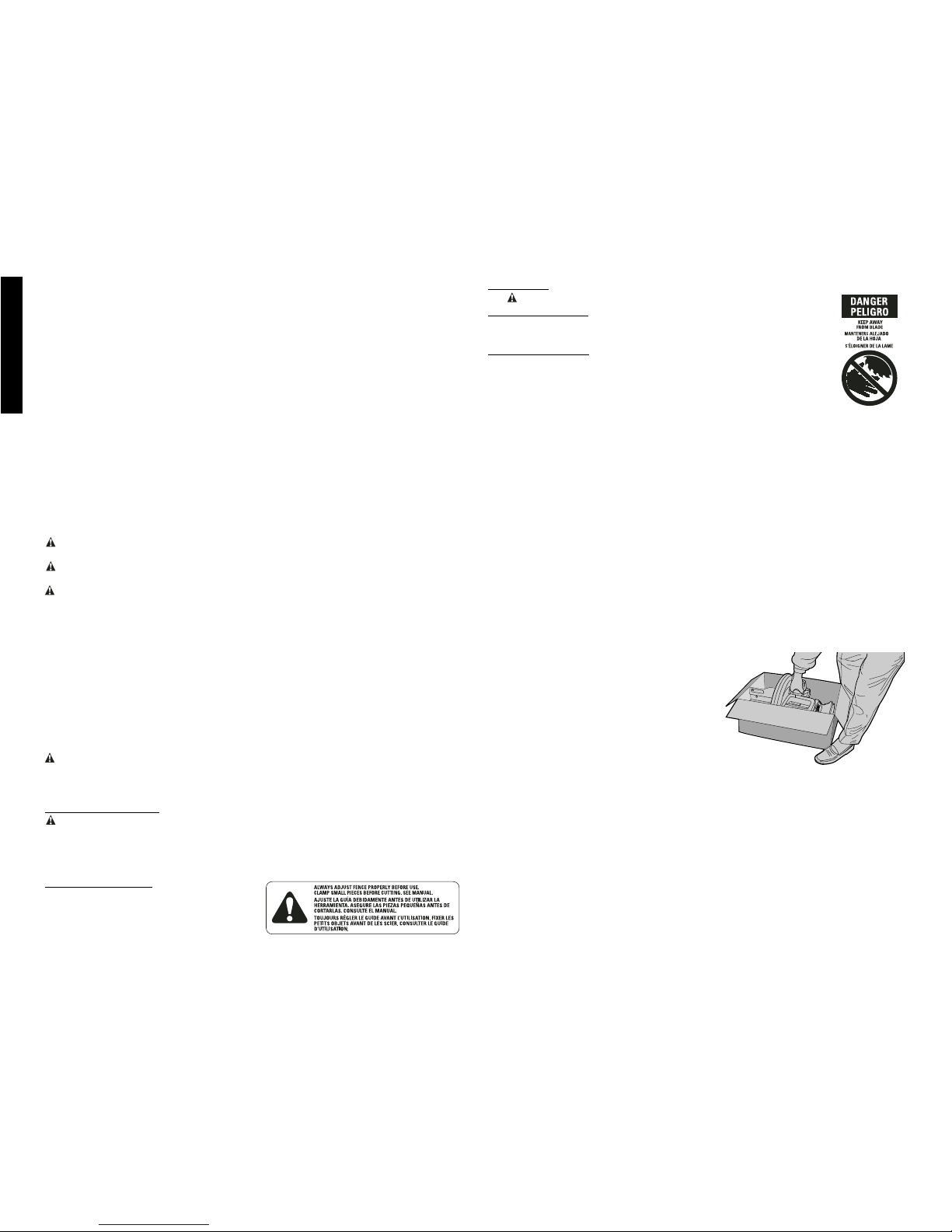
•SECURE WORK. Use clamps or vise when you cannot secure the workpiece on the
table and against the fence by hand or when your hand will be dangerously close to the
blade (within 6”).
•DON’T OVERREACH. Keep proper footing and balance at all times.
•MAINTAIN TOOLS WITH CARE. Keep tools sharp and clean for best and safest per-
formance. Follow instructions for lubricating and changing accessories.
•DISCONNECT TOOLS before servicing; when changing accessories such as blades,
bits, cutters, etc.
•REDUCE THE RISK OF UNINTENTIONAL STARTING. Make sure switch is in OFF
position before plugging in.
•USE RECOMMENDED ACCESSORIES. Consult the instruction manual for recommend-
ed accessories. The use of improper accessories may cause risk of injury to persons.
•NEVER STAND ON TOOL. Serious injury could occur if the tool is tipped or if the cut-
ting tool is unintentionally contacted.
•CHECK DAMAGED PARTS. Before further use of the tool, a guard or other part that is
damaged should be carefully checked to determine that it will operate properly and per-
form its intended function—check for alignment of moving parts, binding of moving
parts, breakage of parts, mounting and any other conditions that may affect its opera-
tion. A guard or other part that is damaged should be properly repaired or replaced. Do
not use tool if switch does not turn it on and off.
•NEVER LEAVE TOOL RUNNING UNATTENDED. TURN POWER OFF. Don’t leave
tool until it comes to a complete stop.
•DO NOT OPERATE ELECTRIC TOOLS NEAR FLAMMABLE LIQUIDS OR IN
GASEOUS OR EXPLOSIVE ATMOSPHERES. Motors in these tools may spark and
ignite fumes.
•EXTENSION CORDS. Make sure your extension cord is in good condition. When using
an extension cord, be sure to use one heavy enough to carry the current your product
will draw. An undersized cord will cause a drop in line voltage resulting in loss of power
and overheating. The following table shows the correct size to use depending on cord
length and nameplate ampere rating. If in doubt, use the next heavier gage. The small-
er the gage number, the heavier the cord.
Minimum Gage for Cord Sets
Volts Total Length of Cord in Feet
120V 0-25 26-50 51-100 101-150
240V 0-50 51-100 101-200 201-300
Ampere Rating
More Not more AWG
Than Than
0-6 18 16 16 14
6 - 10 18 16 14 12
10 - 12 16 16 14 12
12 - 16 14 12 Not Recommended
Additional Safety Rules For Miter Saws
CAUTION: FAILURE TO HEED THESE WARNINGS MAY RESULT IN PERSONAL
INJURY AND SERIOUS DAMAGE TO THE SAW.
• DO - Protect electric supply line with at least a 15 ampere time-delay fuse or a circuit
breaker.
• DO - Make certain the blade rotates in the correct direction and that the teeth at the
bottom of the blade are pointing to the rear of the miter saw.
• DO - Be sure all clamp handles are tight before starting any operation.
• DO - Be sure all blade and clamp washers are clean and recessed sides of collars are
against blade. Tighten arbor screw securely.
• DO - Keep saw blade sharp.
• DO - Keep motor air slots free of chips and dirt.
• DO - Use blade guards at all times.
• DO - Keep hands out of path of saw blade.
• DO - Shut off power, disconnect cord from power source and wait for saw blade to stop
before servicing or adjusting tool.
• DO - Support long work with an outboard tool rest.
• DO NOT - Attempt to operate on anything but designated voltage.
• DO NOT - Operate unless all clamp handles are tight.
• DO NOT - Use blades larger or smaller than those which are recommended.
• DO NOT - Wedge anything against fan to hold motor shaft.
• DO NOT - Force cutting action. (Stalling or partial stalling of motor can cause major
damage. Allow motor to reach full speed before cutting.)

English
2
• DO NOT - Cut ferrous metals (Those with any iron or steel content) or any masonry.
• DO NOT - Use abrasive wheels. The excessive heat and abrasive particles generated
by them will damage the saw.
• DO NOT - Allow anyone to stand behind saw.
• DO NOT - Apply lubricants to the blade when it’s running.
• DO NOT - Place either hand in the blade area when the saw is connected to the power
source.
• DO NOT - Use blades rated less than 5500 R.P.M.
• DO NOT - Cut small pieces without clamping. Keep hands 6” or more from blade.
• DO NOT - Operate saw without guards in place.
• DO NOT - Perform any operation freehand.
• DO NOT - Reach around or behind saw blade.
• DO NOT - Place hands closer than 6 inches from the saw blade.
• DO NOT - Reach underneath the saw unless it is turned off and unplugged. The saw
blade is exposed on the underside of the saw.
• DO NOT - Move either hand from saw or workpiece or raise arm until blade has
stopped.
• DO NOT - Use without Kerf Plate or when kerf slot is wider than 7/16".
• DO NOT - Use lubricants or cleaners (particularly spray or aerosol) in the vicinity of the
plastic guard. The polycarbonate material used in the guard is subject to attack by
certain chemicals.
CAUTION: Do not connect unit to electrical power source until complete instructions are
read and understood.
CAUTION: Wear appropriate personal hearing protection during use. Under some
conditions and duration of use, noise from this product may contribute to hearing loss.
WARNING: Some dust created by power sanding, sawing, grinding, drilling, and other
construction activities contains chemicals known to cause cancer, birth defects or other
reproductive harm. Some examples of these chemicals are:
• lead from lead-based paints,
• crystalline silica from bricks and cement and other masonry products, and
• arsenic and chromium from chemically-treated lumber (CCA).
Your risk from these exposures varies, depending on how often you do this type of work.
To reduce your exposure to these chemicals: work in a well ventilated area, and work with
approved safety equipment, such as those dust masks that are specially designed to filter
out microscopic particles.
•Avoid prolonged contact with dust from power sanding, sawing, grinding,
drilling, and other construction activities. Wear protective clothing and wash
exposed areas with soap and water. Allowing dust to get into your mouth, eyes, or lay
on the skin may promote absorption of harmful chemicals.
WARNING: Use of this tool can generate and/or disburse dust, which may cause serious
and permanent respiratory or other injury. Always use NIOSH/OSHA approved respiratory
protection appropriate for the dust exposure. Direct particles away from face and body.
For your convenience and safety, the following warning labels are on your miter saw.
ON MOTOR HOUSING:
WARNING: FOR YOUR OWN SAFETY, READ INSTRUCTION MANUAL BEFORE
OPERATING SAW.
WHEN SERVICING, USE ONLY IDENTICAL REPLACEMENT PARTS.
ALWAYS WEAR EYE PROTECTION.
DO NOT EXPOSE TO RAIN OR USE IN DAMP LOCATIONS.
ON MOVING FENCE:
ALWAYS ADJUST FENCE PROPERLY
BEFORE USE. Clamp small pieces
before cutting. See manual.
ON GUARD:
DANGER – KEEP AWAY FROM BLADE.
ON UPPER GUARD:
PROPERLY SECURE BRACKET WITH BOTH SCREWS BEFORE
USE.
ON DETENT PLATE: (2 PLACES)
ALWAYS TIGHTEN ADJUSTMENT KNOBS BEFORE USE.
KEEP HANDS 6" FROM PATH OF SAW BLADE. NEVER PER-
FORM ANY OPERATION FREEHAND. NEVER CROSS ARMS IN
FRONT OF BLADE. THINK! YOU CAN PREVENT ACCIDENTS.
DO NOT OPERATE SAW WITHOUT GUARDS IN PLACE.
NEVER REACH IN BACK OF SAW BLADE. TURN OFF TOOL, KEEP SAW HEAD
DOWN AND WAIT FOR SAW BLADE TO STOP BEFORE MOVING HANDS,
WORKPIECE OR CHANGING SETTINGS. UNPLUG TOOL BEFORE CHANGING
BLADE, MOVING OR SERVICING UNIT.
Electrical Connection
Be sure your power supply agrees with the nameplate marking. 120 volts, AC means that
your saw will operate on alternating current only. A voltage decrease of 10 percent or more
will cause a loss of power and overheating. All DEWALT tools are factory tested. If this tool
does not operate, check the power supply.
Unpacking Your Saw
Check the contents of your miter saw carton to make sure that you have received all parts.
In addition to this instruction manual, the carton should contain:
1. One No. DW703 miter saw with blade.
2. One blade wrench in wrench pocket shown in Figure 4.
3. One No. DW7053 Dust Bag.
Familiarization
Your miter saw is fully assembled in the carton.
Open the box and lift the saw out by the conven-
ient carrying handle, as shown in Figure 1.
Place the saw on a smooth, flat surface such as a
workbench or strong table.
Examine Figures 2 and 3 to become familiar with
the saw and its various parts. The section on
adjustments will refer to these terms and you
must know what and where the parts are.
Press down lightly on the operating handle and
pull out the lock down pin, as shown in Figure 4.
Gently release the downward pressure and allow the arm to rise to its full height. Use the
lock down pin when carrying the saw from one place to another. Always use the carrying
handle to transport the saw or the hand indentations shown in Figure 3.
Specifications
CAPACITY OF CUT
50 degree miter left and right
48 degree bevel left: 3 degree right
0 degree miter
Max. Height 3.5" Result Width 3.5"
Max. Width 6.1" Result Height 1.25"
45 degree miter
Max. Height 3.5" Result Width 2.4"
Max. Width 4.2" Result Height 1.25"
FIG. 1

English
3
45 degree bevel
Max. Height 2.3" Result Width 3.5"
Max. Width 6.1" Result Height .75"
31.62 degree miter and 33.85 bevel
Max. Width 5.25" Result Height .9"
DRIVE
120 Volt Motor
2200 Watts 15 Amp Motor
5000 RPM Cut Helical Gears with Roller and Ball Bearings
Carbide Blade Automatic Electric Brake
Optional Accessories
The following accessories, designed for your saw, may be helpful. In some cases, other
locally obtained work supports, length stops, clamps, etc., may be more appropriate. Use
care in selecting and using accessories.
Extension, Work Support: DW7080
Used to support long overhanging workpieces, the work support is user assembled.
Your saw table is designed to accept two work supports; one on each side.
Adjustable Length Stop: DW7051
Requires the use of one work support. It is used to make repetitive cuts of the same
length from 0 to 42".
Clamp: DW7082
Used for firmly clamping workpiece to the saw fence for precision cutting.
Crown Molding Fence: DW7084
Used for precision cutting of crown molding.
Miter Saw Work Station: DW730
Workstation provides fast, easy set up for material support and accurate measuring
system.
SAW BLADES: ALWAYS USE 10" SAW BLADES WITH 5/8" (16mm) ARBOR HOLES.
SPEED RATING MUST BE AT LEAST 5500 RPM.
DEWALT NO. OF BLADE APPLICATION TYPE OF CUT
BLADE TEETH DESC.
RANGE
Series 20 40 Thin Kerf Gen. Purpose Smooth,
Construction Yellow Rim (Trim, Decking, Splinter Free
Coating Framing)
Series 20 60 Thin Kerf Fine Trim Very Smooth,
Construction Yellow Rim Molding Splinter Free
Coating
Series 40 40 Laser Cut Body Gen. Purpose Smooth,
Woodworking Large Carbide (Trim, Decking, Splinter Free
Teeth Framing)
Series 40 60 Laser Cut Body Fine Trim, Very Smooth,
Woodworking Large Carbide Molding Splinter Free
Teeth
Series 40 80 Laser Cut Body Fine Trim Ultra Smooth,
Woodworking Large Carbide Molding Splinter Free
Teeth Decorative
Hardwood
& Plywood
Series 40 80 Laser Cut Body Melamines, Ultra Smooth
Woodworking Large Carbide Veneers, Chip/Splinter
Teeth, Special Laminates Free
Tooth Geometry
ALWAYSADJUSTFENCE
PROPERLYBEFOREUSE
DW7080
DW7051
LOCKNUTS
END PLATE
KNOBS
BOTTOM HOLE
(USE IF ON
RIGHT SIDE)
BRACKET
TOP HOLE
(USE IF ON
LEFT SIDE)
DW7082
DW7084

English
4
Series 40 60 Laser Cut Body Plastics, Corian®Very Smooth
Woodworking Special Tooth and other solid Chip Free
Geometry surface materials
Series 40 80 Laser Cut Body Non-ferrous metals Very Smooth
Woodworking Special Tooth (aluminum, copper, Burr Free
Geometry brass, etc.)
Stabilizer
Your saw includes a stabilizer (Fig.2). This must be in place and in contact with the work
surface at all times while using your saw. This stabilizer is factory installed and needs no
adjustment.
Accessories
Recommended accessories for use with your tool are available at extra cost from your local
retailer or authorized service center.
CAUTION: The use of any non-recommended accessory such as dado sets, molding
cutters, or abrasive wheels may be hazardous.
If you need assistance in locating any accessory, please contact DEWALT Industrial Tool
Co., 701 East Joppa Road, Baltimore, MD 21286 or call 1-800-4-DEWALT (1-800-433-
9258).
FIG. 2
GUARD
RIGHT SIDE
FENCE
MITER
CLAMP KNOB
MITER LATCH
MITER SCALE
BENCH
MOUNTING
HOLES
LEFT SIDE FENCE
CLAMPING KNOB
REAR
GUARD
OPERATING
HANDLE
TABLE
BASE
HOLES FOR
EXTENSION KIT
STABILIZER BAR
FIG. 3 TRIGGER
SWITCH CARRYING
HANDLE
SPINDLE LOCK
BUTTON
LEFT SIDE
FENCE
MITER CLAMP
KNOB
MOTOR
HOUSING
REAR
GUARD BEVEL
STOP
BEVEL
SCALE
MITER LATCH MITER
SCALE
HAND
INDENTATION
BEVEL CLAMP
KNOB
DUST
SPOUT
MOTOR
END CAP
Bench Mounting
Holes are provided in all four feet to facilitate bench mounting, as shown in Figure 2. (Two
different sized holes are provided to accommodate different sizes of screws. Use either
hole, it is not necessary to use both.) Always mount your saw firmly to prevent movement.
To enhance the tool’s portability, it can be mounted to a piece of 1/2" or thicker plywood
which can then be clamped to your work support or moved to other job sites and
reclamped.
NOTE: If you elect to mount your saw to a piece of plywood, make sure that the mounting
screws don’t protrude from the bottom of the wood. The plywood must sit flush on the work
support. When clamping the saw to any work surface, clamp only on the clamping bosses
where the mounting screw holes are located. Clamping at any other point will surely inter-
fere with the proper operation of the saw.
CAUTION: To prevent binding and inaccurate cuts, be sure the mounting surface is not
warped or otherwise uneven. If the saw rocks on the surface place a thin piece of materi-
al under one saw foot until the saw sits firmly on the mounting surface.

English
5
IMPORTANT SAFETY
INSTRUCTIONS
Changing or Installing a New Saw
Blade (Fig. 5, 6)
CAUTION:
• Never depress the spindle lock button while the blade is
under power or coasting.
• Do not cut ferrous metal (containing iron or steel) or
masonry or fiber cement product with this miter saw.
Removing the Blade
1. Unplug the saw.
2. Raise the arm to the upper position and raise the lower
guard (A) as far as possible.
3. Loosen, but do not remove guard bracket screw (B)
until the bracket can be raised far enough to access
the blade screw. Lower guard will remain raised due to
the position of the guard bracket screw.
4. Depress the spindle lock button (Fig. 3) while carefully
rotating the saw blade by hand until the lock engages.
5. Keeping the button depressed, use the other hand and
the wrench provided (D) to loosen the blade screw.
(Turn clockwise, left-hand threads)
6. Remove the blade screw (E), outer clamp washer (F),
and blade (G). The 1" (25.4mm) blade adapter (H), if
used, and the inner clamp washer (I), may be left on
the spindle.
NOTE: For blades with a blade hole of 5/8" (15.88mm), the
1" (25.4mm) blade adapter is not used.
Installing a Blade
1. Unplug the saw.
2. With the arm raised, the lower guard held open and the
pivot plate raised, place the blade on the spindle, onto
the blade adapter [if using a blade with a 1" (25.4mm)
diameter blade hole] and against the inner clamp
washer with the teeth at the bottom of the blade point-
ing toward the back of the saw.
3. Assemble the outer clamp washer onto the spindle.
4. Install the blade screw and, engaging the spindle lock,
tighten the screw firmly with wrench provided. (Turn
counterclockwise, left-hand threads)
NOTE: When using blades with a 5/8" (15.88mm) diame-
ter blade hole, the blade adapter will not be used and
should be stored in a safe place for future use.
5. Return the guard bracket to its original position and
firmly tighten the guard bracket screw to hold bracket
in place.
WARNING:
• The guard bracket must be returned to
its original position and the screw
tightened before activating the saw.
FIG. 4
LOCK
DOWN
PIN
BLADE
WRENCH
FIG. 5
FIG. 6
FIG. 7
K
L
M
J
FIG. 8
FIG. 9
MITER
CLAMP
KNOB
MITER
SCALE
ADJUSTMENT SCREW
(three of these)
MITER LATCH
A
B
D
EF
G
I
H

English
6
• Failure to do so may allow the guard to
contact the spinning saw blade result-
ing in damage to the saw and severe
personal injury.
Transporting the Saw
TURN OFF AND UNPLUG THE MITER SAW BEFORE
ATTEMPTING TO MOVE IT OR MAKE ANY ADJUST-
MENTS WHAT-SO-EVER!
In order to conveniently carry the miter saw from place to
place, a carrying handle has been included on the top of
the saw arm, as shown in Figure 3. To transport the saw,
lower the arm and depress the lock down pin shown in
Figure 4.
Adjustments
PERFORM ALL ADJUSTMENTS WITH THE MITER
SAW UNPLUGGED
NOTE: Your miter saw is fully and accurately adjusted at
the factory at the time of manufacture. If readjustment due
to shipping and handling or any other reason is required,
follow the steps below to adjust your saw.
Once made, these adjustments should remain accurate.
Take a little time now to follow these directions carefully to
maintain the accuracy of which your saw is capable.
MITER SCALE ADJUSTMENT
Place a square against the saw’s fence and blade, as
shown in Figure 8. (Do not touch the tips of the blade teeth
with the square. To do so will cause an inaccurate meas-
urement.) Loosen the miter clamp knob (see Fig. 9) and
swing the miter arm until the miter latch locks it at the 0˚
miter position. Do not tighten the clamp knob. If the saw
blade is not exactly perpendicular to the fence, loosen the
three screws that hold the miter scale to the base (shown
in Fig. 9) and move the scale/miter arm assembly left or
right until the blade is perpendicular to the fence, as meas-
ured with the square. Retighten the three screws. Pay no
attention to the reading of the miter pointer at this point.
MITER POINTER ADJUSTMENT
Loosen the miter clamp knob and squeeze the miter latch
to move the miter arm to the zero position, as shown in
Figure 9. With the miter clamp knob loose allow the miter
latch to snap into place as you rotate the miter arm past
zero. Observe the pointer and miter scale through the
viewing opening shown in Figure 10. If the pointer does not
indicate exactly zero, loosen the pointer screw, adjust the
pointer to 0˚ and retighten.
BEVEL SQUARE TO TABLE
To align the blade square to the rotary table, lock the arm
in the down position. Place a square against the blade tak-
ing care to not have the square on top of a tooth, as shown
in Figure 11B. Loosen the Bevel Clamp Knob so that you
can move the Bevel Arm. Move the Bevel Arm as neces-
FIG. 10
MITER
SCALE POINTER
FIG. 11B
FIG. 11A
BEVEL
HOUSING
STOP SCREW
LOCK NUT
FIG. 12
BEVEL STOP
BEVEL
POINTER
SCREW
BEVEL
SCALE
LEFT SIDE
FENCE
CLAMPING
KNOB
FIG. 13
LEFT SIDE
BEVEL STOP
SCREW
FIG. 14
TRIGGER
SWITCH
HOLE FOR PADLOCK

English
7
sary so that the blade is at zero degrees bevel to the table.
If the Bevel Arm needs adjustment, loosen the lock nut on
the right side Bevel Stop as shown in Figure 12, and adjust
the stop screw as necessary. Hold the stop screw in place
and tighten the lock nut.
BEVEL POINTER
If the bevel pointer does not indicate zero, loosen the screw
that holds it in place and move the pointer as necessary.
SUGGESTION: For accuracy, set the top edge so that it
aligns with zero.
BEVEL STOP
To set the 45 degree bevel stop shown in Figure 7, first
loosen the left side fence clamping knob and slide the left
side fence as far as it will go to the left. Move the arm to
the left until it stops on the left bevel stop screw. If the bevel
pointer (J) does not indicate exactly 45 degrees, loosen
the left side bevel stop lock nut (K) and turn the screw (L)
downwards. Move the arm to the left and tighten the bevel
clamp knob (M) firmly when the bevel pointer indicates
exactly 45 degrees. Adjust the left side bevel stop screw
upwards until it firmly touches the bevel stop. Retighten the
nut while holding the screw from turning.
To achieve 3 degree right bevel or 48 degree left bevel, the
stop screws must be adjusted to allow the arm to move to
the desired location. The bevel stops will need readjust-
ment to the zero and 45 degree positions after cuts are
made.
FENCE ADJUSTMENT
Turn Off and Unplug the Miter Saw
To bevel UP TO 48 degrees left, the left side of the fence
can be adjusted to the left to provide clearance. To adjust
the fence, loosen the knob shown in Figure 13 and slide the
fence to the left. Make a dry run with the saw turned off and
check for clearance. Adjust the fence to be as close to
the blade as practical to provide maximum workpiece
support, without interfering with arm up and down move-
ment. Tighten knob securely. When the bevel operations
are complete, don’t forget to relocate the fence to the right.
GUARD ACTUATION AND VISIBILITY
The blade guard on your saw has been designed to auto-
matically raise when the arm is brought down and to lower
over the blade when the arm is raised.
The guard can be raised by hand when installing or remov-
ing saw blades or for inspection of the saw. NEVER RAISE
THE BLADE GUARD MANUALLY UNLESS THE SAW IS
TURNED OFF.
NOTE: Certain special cuts will require that you manually
raise the guard. See section on cutting base molding up to
3-1/2" high (page 10).
The front section of the guard is louvered for visibility
while cutting. Although the louvers dramatically reduce
flying debris, they are openings in the guard and safety
glasses should be worn at all times when viewing through
the louvers.
PROPER HAND POSITION
FIG. 15
IMPROPER HAND POSITION
FIG. 15A

English
8
AUTOMATIC ELECTRIC BRAKE
Your saw is equipped with an automatic electric blade
brake which stops the saw blade within 5 seconds of trig-
ger release. This is not adjustable.
On occasion, there may be a delay after trigger release to
brake engagement. On rare occasions, the brake may not
engage at all and the blade will coast to a stop.
If a delay or “skipping” occurs, turn the saw on and off 4 or
5 times. If the condition persists, have the tool serviced by
an authorized DEWALT service center.
Always be sure the blade has stopped before removing it
from the kerf. The brake is not a substitute for guards or for
ensuring your own safety by giving the saw your complete
attention.
Brushes
DISCONNECT PLUG FROM POWER SUPPLY
Inspect carbon brushes regularly by unplugging tool,
removing the motor end cap, (Figure 3) removing the brush
cap and withdrawing the brush assembly. Keep brushes
clean and sliding freely in their guides. Always replace a
used brush in the same orientation in the holder as it was
prior to its removal. Use only identical DEWALT brushes.
Use of the correct grade of brush is essential for proper
operation of electric brake. New brush assemblies are
available at DEWALT service centers. The tool should be
allowed to “run in” (run at no load) for 10 minutes before use
to seat new brushes. The electric brake may be erratic in
operation until the brushes are properly seated (worn in).
While “running in” DO NOT TIE, TAPE, OR OTHERWISE
LOCK THE TRIGGER SWITCH ON. HOLD BY HAND
ONLY.
Operation
Plug the saw into any household 60 Hz power source.
Refer to the nameplate for voltage. Be sure the cord will
not interfere with your work.
SWITCH
To turn the saw on, depress the trigger switch shown in
Figure 14. To turn the tool off, release the switch. There is
no provision for locking the switch on, but a hole is provid-
ed in the trigger for insertion of a padlock to lock the saw
off.
CUTTING WITH YOUR SAW
NOTE: Although this saw will cut wood and many non-fer-
rous materials, we will limit our discussion to the cutting of
wood only. The same guidelines apply to the other materi-
als. DO NOT CUT FERROUS (IRON AND STEEL) MATE-
RIALS OR MASONRY WITH THIS SAW. Do not use any
abrasive blades.
CROSSCUTS
Cutting of multiple pieces is not recommended but can be
done safely by ensuring that each piece is held firmly
against the table and fence. A crosscut is made by cutting
wood across the grain at any angle. A straight crosscut is
made with the miter arm at the zero degree position. Set
the miter arm at zero, hold the wood on the table and firm-
ly against the fence. Turn on the saw by squeezing the trig-
ger switch shown in Figure 14.
When the saw comes up to speed (about 1 second) lower
the arm smoothly and slowly to cut through the wood. Let
the blade come to a full stop before raising arm.
Miter crosscuts are made with the miter arm at some angle
other than zero. This angle is often 45 degrees for making
corners, but can be set anywhere from zero to 50 degrees
left or right. After selecting the desired miter angle, be sure
to tighten the miter clamp knob. Make the cut as described
above.
BEVEL CUTS
A bevel cut is a crosscut made with the saw blade at a
bevel to the wood. In order to set the bevel, loosen the
bevel clamp knob and move the saw to the left as desired.
(It is necessary to move the left side of the fence to
allow clearance). Once the desired bevel angle has been
set, tighten the bevel clamp knob firmly.
Bevel angles can be set from 3 degrees right to
48 degrees left and can be cut with the miter arm set
between zero and 50 degrees right or left. Ensure the
fence has been adjusted properly. When cutting left bevel,
or right miter compound cuts, it will be necessary to
remove the adjustable fence.
QUALITY OF CUT
The smoothness of any cut depends on a number of vari-
ables. Things like material being cut, blade type, blade
sharpness and rate of cut all contribute to the quality of
the cut.
When smoothest cuts are desired for molding and other
precision work, a sharp (60 - 80 tooth carbide) blade and
a slower, even cutting rate will produce the desired results.
Ensure that material does not creep while cutting. Clamp it
securely in place. Always let the blade come to a full stop
before raising arm.
If small fibers of wood still split out at the rear of the work-
piece, apply a piece of masking tape on the wood where
the cut will be made. Saw through the tape and carefully
remove tape when the cut is finished.
For varied cutting applications, refer to the list of recom-
mended saw blades for your saw and select the one that
best fits your needs. (Page 3)
BODY AND HAND POSITION (FIG. 15)
Proper positioning of your body and hands when operating
the miter saw will make cutting easier, more accurate and
safer. Never place hands near cutting area. Place hands
no closer than 6" from the blade. Hold the workpiece tight-
ly to the table and the fence when cutting. Keep hands in
position until the trigger has been released and the blade
has completely stopped. ALWAYS MAKE DRY RUNS
FIG. 16 FIG. 17
FIG. 18
A.
B.
ANGLE “A”
FIG. 19
MITER
SCALE
FIG. 20

English
9
(UNPOWERED) BEFORE FINISH CUTS SO THAT YOU
CAN CHECK THE PATH OF THE BLADE. DO NOT
CROSS HANDS, AS SHOWN IN FIGURE 15A.
Keep both feet firmly on the floor and maintain proper bal-
ance. As you move the miter arm left and right, follow it and
stand slightly to the side of the saw blade. Sight through
the guard louvers when following a pencil line.
CLAMPING THE WORKPIECE
Turn Off and Unplug Saw
If you cannot secure the workpiece on the table and
against the fence by hand, (irregular shape, etc.) or your
hand would be less than 6” from the blade, a clamp or
other fixture should be used.
For best results use the DW7082 clamp made for use with
your saw. It is available through your local retailer or
DEWALT service center at extra cost.
Other aids such as spring clamps, bar clamps or C-clamps
may be appropriate for certain sizes and shapes of mate-
rial. Use care in selecting and placing these clamps. Take
time to make a dry run before making the cut. The left
fence will slide from side to side to aid in clamping.
SUPPORT FOR LONG PIECES
Turn Off and Unplug Saw
ALWAYS SUPPORT LONG PIECES
Support long workpieces using any convenient means
such as sawhorses or similar devices to keep the ends
from dropping. For best results, use the DW7080 exten-
sion work support to extend the table width of your saw.
Also available to help hold long workpieces is the DW730
Miter Saw Workstation, available for purchase at your
dealer.
CUTTING PICTURE FRAMES, SHADOW BOXES AND
OTHER FOUR SIDED PROJECTS
To best understand how to make the items listed here, we
suggest that you try a few simple projects using scrap
wood until you develop a “FEEL” for your saw.
Your saw is the perfect tool for mitering corners like the one
shown in Figure 16. Sketch A in Figure 16 shows a joint
made by using the bevel adjustment to bevel the edges of
the two boards at 45 degrees each to produce a 90 degree
corner. For this joint the miter arm was locked in the zero
position and the bevel adjustment was locked at 45
degrees. The wood was positioned with the broad flat side
against the table and the narrow edge against the fence.
The cut could also be made by mitering right and left with
the broad surface against the fence.
CUTTING TRIM MOLDING AND OTHER FRAMES
Sketch B in Figure 16 shows a joint made by setting the
miter arm at 45 degrees to miter the two boards to form a
90 degree corner. To make this type of joint, set the bevel
adjustment to zero and the miter arm to 45 degrees. Once
again, position the wood with the broad flat side on the
table and the narrow edge against the fence.
The two sketches in Figure 16 are for four sided objects
only.
As the number of sides changes, so do the miter and bevel
angles. The chart below gives the proper angles for a vari-
ety of shapes. The chart assumes that all sides are of
equal length. For a shape that is not shown in the chart,
use the following formula. 180 degrees divided by the
number of sides equals the miter or bevel angle.
- EXAMPLES -
NO. SIDES ANGLE MITER OR BEVEL
445°
536°
630°
7 25.7°
8 22.5°
920°
10 18°
CUTTING COMPOUND MITERS
A compound miter is a cut made using a miter angle and a
bevel angle at the same time. This is the type of cut used
to make frames or boxes with slanting sides like the one
shown in Figure 17.
NOTE: If the cutting angle varies from cut to cut, check that
the bevel clamp knob and the miter lock knob are securely
tightened. These knobs must be tightened after making any
changes in bevel or miter.
The chart shown on page 12 will assist you in selecting the
proper bevel and miter settings for common compound
miter cuts. To use the chart, select the desired angle “A”
(Figure 18) of your project and locate that angle on the
appropriate arc in the chart. From that point follow the
chart straight down to find the correct bevel angle and
straight across to find the correct miter angle.
Set your saw to the prescribed angles and make a few trial
cuts. Practice fitting the cut pieces together until you devel-
op a feel for this procedure and feel comfortable with it.
Example: To make a 4 sided box with 26° exterior angles
(Angle A, Figure 18), use the upper right arc. Find 26° on
the arc scale. Follow the horizontal intersecting line to
either side to get miter angle setting on saw (42°).
Likewise, follow the vertical intersecting line to the top or
bottom to get the bevel angle setting on the saw (18°).
Always try cuts on a few scrap pieces of wood to verify set-
tings on saw.
MITER SCALE
The scale is used when calculating angles. To calculate
the proper miter angle, divide 180 degrees by the number
of sides of the box or frame. Refer to the chart on page 9
for some examples.
VERNIER SCALE (FIG. V1, V2)
Your saw is equipped with a vernier scale for added preci-
sion. The vernier scale allows you to accurately set miter
FIG. V1
FIG. V2
CENTER MARK ON VERNIER SCALE ALIGNS WITH
DESIRED WHOLE ANGLE ON MITER SCALE
(24° RIGHT MITER)
1/4° VERNIER MARK ALIGNS WITH CLOSEST WHOLE
DEGREE MARK ON MITER SCALE (24 1/4° RIGHT MITER)
FIG. 21

English
10
angles to the nearest 1/4 degree (15 minutes). To use the
vernier scale follow the steps listed below.
(As an example, let’s assume that the angle you want to
miter is 24-1/4 degrees right).
1. Turn off miter saw.
2. Set the miter angle to the nearest whole degree
desired by aligning the center mark in the vernier
scale, shown in figure V1, with the whole degree num-
ber etched in the miter scale. Examine Figure V1
closely; the setting shown is 24 degrees right miter.
3. To set the additional 1/4 degree, squeeze the miter
arm lock and carefully move the arm to the RIGHT until
the 1/4 degree vernier mark aligns with the CLOSEST
degree mark on the miter scale. In our example, the
closest degree mark on the miter scale happens to be
25 degrees. Figure V2 shows a setting of 24-1/4
degrees right miter.
For settings that require partial degrees (1/4, 1/2, 3/4
degrees) align the desired vernier mark with the CLOS-
EST degree mark on the miter scale, as described above.
(The plastic vernier plate is inscribed with marks for 1/4,
1/2, 3/4 and 1 degrees. Only the 1/2 degree is numerical-
ly labeled.)
WHEN MITERING TO THE RIGHT
To increase the miter angle when mitering to the right,
move the arm to align the appropriate vernier mark with the
closest mark on the miter scale to the right. To decrease
the miter angle when mitering to the right, move the arm to
align the appropriate vernier mark with the closest mark on
the miter scale to the left.
WHEN MITERING TO THE LEFT
To increase the miter angle when mitering to the left, move
the arm to align the appropriate vernier mark with the clos-
est mark on the miter scale to the left. To decrease the
miter angle when mitering to the left, move the arm to align
the appropriate vernier mark with the closest mark on the
miter scale to the right.
CUTTING BASE MOLDING
ALWAYS MAKE A DRY RUN WITHOUT POWER
BEFORE MAKING ANY CUTS.
Straight 90 degree cuts :
Position the wood against the fence as shown in Figure
20. Turn on the saw, allow the blade to reach full speed
and lower the arm smoothly through the cut.
CUTTING BASE MOLDING UP TO 3-1/2" HIGH
VERTICALLY AGAINST THE FENCE
Position molding as shown in Figure 21.
All cuts are made with the back of the molding against the
fence and bottom of the molding against the base.
INSIDE CORNER:
Left side
1. Miter left 45°
2. Save left side of cut
Right side
1. Miter Right 45°
2. Save right side of cut
OUTSIDE CORNER:
Left side
1. Miter right at 45°
2. Save left side of cut
Right side
1. Miter left at 45°
2. Save right side of cut
Material up to 3.5" (3-1/2)" can be cut as described above.
For wider boards [up to 4.25" (4-1/4")] several minor con-
cessions must be made.
When cutting a board between 3.5" (3-1/2") and 4.25"
(4-1/4") in width the roller on the tip of the guard could
hang up on the workpiece. If this occurs, simply place your
right thumb on the upper side of the guard and roll the
guard up just enough to clear the workpiece, as shown in
Figure 24. Once you have cleared the workpiece, you can
release the guard and it will continue to open as the cut
progresses.
When mitering to the right side of a base molding wider
than 3.5" (3-1/2") standing vertically against the fence as in
Figure 21, the saw can only cut through the board up to 1
inch from the end of the board. Trying to cut more than an
inch will cause the saw’s gear case to interfere with the
workpiece. If you want to cut base molding between 3-1/2"
and 4-1/4" wide vertically follow the directions below.
CUTTING 3-1/2"– 4-1/4" BASE MOLDING VERTICALLY
AGAINST THE FENCE
• Position molding as shown in Figure 21.
• All cuts made with the back of the molding against the
fence
INSIDE CORNER:
Left side
1. Position molding with bottom of molding against
the base of the saw
2. Miter left 45°
3. Save left side of cut
Right side
1. Position molding with top of the molding resting on
the base of the saw
2. Miter left 45°
3. Save left side of cut
OUTSIDE CORNER:
Left side
1. Position molding with bottom of molding against
the base of the saw
2. Miter right 45°
3. Save left side of cut
NOTE: If the cut must be made somewhere other than
1" from the end of the molding: cut off the molding at
FIG. 22
FIG. 23
FIG. 24

English
11
10
10
10
20
20
20
30
30
30
40
40
40
50
50
50
60
60
60
70
70
70
80
80
80
TABLE 1: COMPOUND MITER CUT
(POSITION WOOD WITH BROAD FLAT SIDE ON THE TABLE AND THE NARROW EDGE AGAINST THE FENCE)
SET THIS MITER ANGLE ON SAW
ANGLE OF SIDE OF BOX (ANGLE A)
SQUARE BOX
6-SIDED BOX
MITER DEGREE SETTING
BEVEL DEGREE SETTING
SET THIS BEVEL ANGLE ON SAW
8-SIDED BOX

English
12
90° approx. 1" longer than your final length then make
the miter cut as described above.
Right side
1. Position molding with bottom of the molding
against the base of the saw
2. Miter left 45°
3. Save the right side of cut
A third method of making the cut necessary is to make a
zero degree miter, 45 degree bevel cut. Your saw can cut
a bevel 6.1" wide.
CUTTING BASE MOLDING LAYING FLAT AND USING
THE BEVEL FEATURE
• All cuts made with the saw set at 45° bevel and 0 miter
• All cuts made with back of molding laying flat on the
saw as shown in figures 22 and 23.
•Move the left side fence out of the path of the blade
before attempting any of the following cuts.
INSIDE CORNER:
Left side
1. Position molding with top of molding against the fence
2. Save left side of cut
Right side
1. Position molding with bottom of the molding against
the fence
2. Save left side of cut
OUTSIDE CORNER:
Left side
1. Position molding with bottom of the molding against
the fence
2. Save right side of cut
Right side
1. Position molding with top of molding against the
fence
2. Save right side of cut
CUTTING CROWN MOLDING
Your miter saw is better suited to the task of cutting
crown molding than any tool made. In order to fit proper-
ly, crown molding must be compound mitered with
extreme accuracy.
The two flat surfaces on a given piece of crown molding
are at angles that, when added together, equal exactly 90
degrees. Most, but not all, crown molding has a top rear
angle (the section that fits flat against the ceiling) of 52
degrees and a bottom rear angle (the part that fits flat
against the wall) of 38 degrees.
Your miter saw has special pre-set miter latch points at
31.62 degrees left and right for cutting crown molding at
the proper angle. There is also a mark on the Bevel scale
at 33.85 degrees.
The chart below gives the proper settings for cutting crown
molding. (The numbers for the miter and bevel settings are
very precise and are not easy to accurately set on your
saw.) Since most rooms do not have angles of precisely 90
degrees, you will have to fine tune your settings anyway.
PRETESTING WITH SCRAP MATERIAL IS
EXTREMELY IMPORTANT!
INSTRUCTIONS FOR CUTTING CROWN
MOLDING LAYING FLAT AND USING THE
COMPOUND FEATURES
1. Move the left side fence out of the path of the blade
before attempting any of the following cuts.
2. Molding laying with broad back surface down flat on
saw table (Fig. 25).
3. The settings below are for all Standard (U.S.) crown
molding with 52° and 38° angles.
FIG. 26
BLADE
FENCE
FENCE
RIGHT
FIG. 25
FENCE
TABLE
CROWN MOLDING FLAT ON TABLE AND AGAINST FENCE
CROWN MOLDING BETWEEN FENCE AND TABLE
TABLE
FENCE
BOTTOM SIDE
OF MOLDING
TOP SIDE
OF MOLDING
FIG. 25A
DW 7084 CROWN
MOLDING FENCE
BEVEL SETTING TYPE OF CUT
LEFT SIDE, INSIDE CORNER:
33.85° 1. Top of molding against fence
2. Miter table set right 31.62°
3. Save left end of cut
RIGHT SIDE, INSIDE CORNER:
33.85° 1. Bottom of molding against fence
2. Miter table set left 31.62°
3. Save left end of cut
LEFT SIDE, OUTSIDE CORNER:
33.85° 1. Bottom of molding against fence
2. Miter table set left 31.62°
3. Save right end of cut
FIG. 27
BLADE
WRONG

English
13
RIGHT SIDE, OUTSIDE CORNER:
33.85° 1. Top of molding against fence
2. Miter table set right 31.62°
3. Save right end of cut
When setting bevel and miter angles for all compound
miters, remember that:
The angles presented for crown moldings are very pre-
cise and difficult to set exactly. Since they can easily
shift slightly and very few rooms have exactly square
corners, all settings should be tested on scrap molding.
PRETESTING WITH SCRAP MATERIAL IS
EXTREMELY IMPORTANT!
ALTERNATIVE METHOD FOR CUTTING CROWN
MOLDING
Place the molding on the table at an angle between the
fence and the saw table, as shown in Figure 25A. Use of the
crown molding fence accessory (DW7084) is highly
recommended because of its degree of accuracy and
convenience. The crown molding fence accessory is
available at extra cost from your local dealer.
The advantage to cutting crown molding using this method
is that no bevel cut is required. Minute changes in the miter
angle can be made without affecting the bevel angle. This
way, when corners other than 90 degrees are encoun-
tered, the saw can be quickly and easily adjusted for them.
Use the crown molding fence accessory (DW7084) to
maintain the angle at which the molding will be on the wall.
INSTRUCTIONS FOR CUTTING CROWN MOLDING
ANGLED BETWEEN THE FENCE AND BASE OF
THE SAW FOR ALL CUTS:
1. Angle the molding so the bottom of the molding (part
which goes against the wall when installed) is against the
fence and the top of the molding is resting on the base of
the saw, as shown in Figure 25A.
2. The angled “flats” on the back of the molding must rest
squarely on the fence and base of the saw.
INSIDE CORNER:
Left side
1. Miter right at 45°
2. Save the right side of cut
Right side
1. Miter left at 45°
2. Save left side of cut
OUTSIDE CORNER:
Left side
1. Miter left at 45°
2. Save right side of cut
Right side
1. Miter right at 45°
2. Save left side of cut
Be sure to properly secure workpiece. Refer to page 3 for
correct saw blade.
Bowed Material:
When cutting bowed material always position it as shown
in Figure 28 and never like that shown in Figure 29.
Positioning the material incorrectly will cause it to pinch the
blade near the completion of the cut.
Cutting Plastic Pipe or Other Round Material
Plastic pipe can be easily cut with your saw. It should be
cut just like wood and CLAMPED OR HELD FIRMLY TO
THE FENCE TO KEEP IT FROM ROLLING. This is
extremely important when making angle cuts.
Cutting Large Material
Occasionally you will encounter a piece of wood a little too
large to fit beneath the blade guard. A little extra height can
be gained by rolling the guard up out of the way, as shown
in Figure 24. Avoid doing this as much as possible, but if
need be, the saw will operate properly and make the big-
ger cut. NEVER TIE, TAPE, OR OTHERWISE HOLD THE
GUARD OPEN WHEN OPERATING THIS SAW.
Maintenance
1. All bearings are sealed. They are lubricated for life and
need no further maintenance.
2. Periodically clean all dust and wood chips from around
AND UNDER the base and the rotary table. Even
though slots are provided to allow debris to pass
through, some dust will accumulate.
3. The brushes are designed to give you several years of
use. If they ever need replacement follow the instruc-
tions on page 6 or return the tool to the nearest serv-
ice center for repair. A list of service center locations is
packed with your tool.
Repairs
To assure product SAFETY and RELIABILITY, repairs,
maintenance and adjustment (including brush inspection
and replacement) should be performed by authorized serv-
ice centers or other qualified service organizations, always
using identical replacement parts.
Three Year Limited Warranty
DEWALT will repair, without charge, any defects due to
faulty materials or workmanship for three years from the
date of purchase. This warranty does not cover part failure
due to normal wear or tool abuse. For further detail of war-
ranty coverage and warranty repair information, visit
www.dewalt.com or call 1-800-4-DEWALT (1-800-433-
9258). This warranty does not apply to accessories or
damage caused where repairs have been made or
attempted by others. This warranty gives you specific legal
rights and you may have other rights which vary in certain
states or provinces.
FIG. 28
FIG. 29
RIGHT
WRONG
FENCE
Special Cuts
NEVER MAKE ANY CUT UNLESS THE MATERIAL IS
SECURED ON THE TABLE AND AGAINST THE FENCE.
Aluminum Cutting:
Certain workpieces, due to their size, shape or surface
finish, may require the use of a clamp or fixture to prevent
movement during the cut. Position the material so that you
will be cutting the thinnest cross section, as shown in Figure
26. Figure 27 illustrates the wrong way to cut these
extrusions. Use a stick wax cutting lubricant when cutting
aluminum. Apply the stick wax directly to the saw blade
before cutting. Never apply stick wax to a moving blade.
The wax, available at most hardware stores and industrial
mill supply houses, provides proper lubrication and keeps
chips from adhering to the blade.

English
14
In addition to the warranty, DEWALT tools are covered by
our:
1 YEAR FREE SERVICE
DEWALT will maintain the tool and replace worn parts
caused by normal use, for free, any time during the first
year after purchase.
90 DAY MONEY BACK GUARANTEE
If you are not completely satisfied with the performance of
your DEWALT Power Tool, Laser, or Nailer for any reason,
you can return it within 90 days from the date of purchase
with a receipt for a full refund – no questions asked.
RECONDITIONED PRODUCT: Reconditioned product is
covered under the 1 Year Free Service Warranty. The 90
Day Money Back Guarantee and the Three Year Limited
Warranty do not apply to reconditioned product.
FREE WARNING LABEL REPLACEMENT: If your
warning labels become illegible or are missing, call
1-800-4-DEWALT for a free replacement.
Troubleshooting Guide
BE SURE TO FOLLOW SAFETY RULES AND INSTRUCTIONS
TROUBLE! SAW WILL NOT START
WHAT’S WRONG? WHAT TO DO…
1. Saw not plugged in 1. Plug in saw
2. Fuse blown or circuit breaker tripped 2. Replace fuse or reset circuit breaker
3. Cord damaged 3. Have cord replaced by authorized service center
4. Brushes worn out 4. Have brushes replaced by authorized service
center or replace them yourself as instructed
on page 8
TROUBLE! SAW MAKES UNSATISFACTORY CUTS
WHAT’S WRONG? WHAT TO DO…
1. Dull blade 1. Replace blade, see page 5
2. Blade mounted backwards 2. Turn blade around, see page 5
3. Gum or pitch on blade 3. Remove blade and clean with turpentine and
coarse steel wool or household oven cleaner
4. Incorrect blade for work being done 4. Change the blade type, see page 5
TROUBLE! BLADE DOES NOT COME UP TO SPEED
WHAT’S WRONG? WHAT TO DO…
1. Extension cord too light or too long 1. Replace with adequate size cord, see page 1
2. Low house current 2. Contact your electric company
TROUBLE! MACHINE VIBRATES EXCESSIVELY
WHAT’S WRONG? WHAT TO DO…
1. Saw not mounted securely to stand or work bench 1. Tighten all mounting hardware, see page 4
2. Stand or bench on uneven floor 2. Reposition on flat level surface, see page 4
3. Damaged saw blade 3. Replace blade, see page 5
TROUBLE! DOES NOT MAKE ACCURATE MITER CUTS
WHAT’S WRONG? WHAT TO DO…
1. Miter scale not adjusted correctly 1. Check and adjust, see page 6
2. Blade is not square to fence 2. Check and adjust, see page 6
3. Blade is not perpendicular to table 3. Check and adjust fence, see page 6
4. Workpiece moving 4. Clamp workpiece securely to fence
TROUBLE! MATERIAL PINCHES BLADE
WHAT’S WRONG? WHAT TO DO…
1. Cutting bowed material 1. Position bowed material as shown on page 13

15
Français
Table des matières
MESURES DE SÉCURITÉ ..................................................................................16
INSTRUCTIONS RELATIVES À LA DOUBLE ISOLATION6
ET AUX FICHES POLARISÉES ..........................................................................16
MESURES DE SÉCURITÉ ADDITIONNELLES ..................................................16
RACCORDEMENT ÉLECTRIQUE ......................................................................18
DÉBALLAGE DE LA SCIE ..................................................................................18
FAMILIARISATION ..............................................................................................18
CARACTERÉRISTIQUES TECHNIQUE..............................................................18
ACCESSOIRES OPTIONELS..............................................................................18
STABILISATEUR ................................................................................................19
ACCESSOIRES ..................................................................................................19
MONTAGE SUR ÉTABLI......................................................................................19
INSTALLATION DE LA LAME ..............................................................................20
TRANSPORT DE LA SCIE ..................................................................................21
RÉGLAGES..........................................................................................................21
RÉGLAGE DE L’ÉCHELLE POUR ONGLETS ............................................22
RÉGLAGE DE L’INDICATEUR DE L’ONGLETS ..........................................22
RÉGLAGE DU BISEAU EN ÉQUERRE ......................................................22
INDICATEUR DU BISEAU ............................................................................22
BUTÉE DU BISEAU......................................................................................22
RÉGLAGE DU GUIDE ..................................................................................22
VISIBILITÉ ET DÉCLENCHEMENT DU PROTÉGE-LAME ........................23
FREIN ÉLECTRIQUE AUTOMATIQUE ........................................................23
BALAIS ................................................................................................................23
FONCTIONNEMENT ..........................................................................................23
INTERRUPTEUR ..........................................................................................23
MÉTHODE DE COUPE ................................................................................23
COUPES EN TRAVERSALES ................................................................................23
COUPES EN BISEAU..............................................................................................24
QUALITÉ DE LA COUPE ........................................................................................24
POSITION DU CORPS ET DES MAINS................................................................24
FIXATION DE LA PIÈCE À OUVRER ..........................................................24
SUPPORT DE LONGS OUVRAGES............................................................25
COUPE DE CADRES, DE COFFRAGES OU D’AUTRES
OUVRAGES QUADRILATÉRAUX ................................................................25
COUPE DE BOISERIES OU D’AUTRES TYPES DE MOULURES ............25
COUPE EN ONGLET À ANGLES COMBINÉS ............................................25
ÉCHELLE DE COUPE EN ONGLET............................................................25
VERNIER ......................................................................................................26
COUPES EN ONGLET ................................................................................26
COUPES DE PLINTHES
..............................................................................
26
COUPE DE MOULURES EN COURONNE..................................................27
TABLEAU 1 ONGLETS MIXTES ........................................................................29
COUPES PARTICULIÈRES
................................................................................
30
ENTRETIEN ........................................................................................................30
RÉPARATIONS ....................................................................................................30
GARANTIE ..........................................................................................................30
GUIDE DE DÉPANNAGE ....................................................................................31

16
Importantes consignes de sécurité
AVERTISSEMENT : lorsqu’on utilise un outil électrique, on doit toujours
suivre les consignes de sécurité, y compris celles décrites ci-dessous, afin
de réduire les risques d’incendie, de choc électrique et de blessure.
LIRE TOUTES LES DIRECTIVES
Double isolation
Afin de protéger l’utilisateur contre les chocs électriques, les outils à double isolation
sont complètement recouverts de deux couches distinctes d’isolant électrique ou d’une
double épaisseur de matière isolante. Les outils possédant ce type d’isolation ne sont
pas destinés à être mis à la terre et, par conséquent, sont munis d’une fiche à deux
broches permettant d’utiliser une rallonge ne nécessitant aucune prise de masse.
REMARQUE : le fait que cet outil soit muni d’une double isolation ne signifie pas que
l’utilisateur doit cesser de suivre les consignes de sécurité qui s’imposent; l’isolation
offre une protection supplémentaire contre les blessures causées par un choc électrique
lorsque les systèmes d’isolation internes font défaut.
MISE EN GARDE : LORS DE L’ENTRETIEN, N’UTILISER QUE DES PIÈCES DE
RECHANGE IDENTIQUES; faire réparer ou remplacer également les cordons endom-
magés, y compris les rallonges.
Fiches polarisées
Afin de réduire les risques de choc électrique, cet outil est muni d’une fiche polarisée
(c’est-à-dire que l’une des lames est plus large que l’autre), et ne peut être raccordé qu’à
une rallonge polarisée et ce, dans un seul sens. On doit l’inverser si on est incapable de
l’enfoncer complètement. Si la fiche ne s’adapte toujours pas, on doit demander à un
électricien qualifié d’installer la prise appropriée. On ne doit jamais modifier la fiche.
Consignes de sécurité relatives à tous les outils
•GARDER LES DISPOSITIFS DE PROTECTION EN PLACE et en bon état de fonc-
tionnement.
•RETIRER LES CLÉS DE RÉGLAGE; prendre l’habitude de s’assurer que les clés de
réglage soient retirées de l’outil avant de le démarrer.
•GARDER LA ZONE DE TRAVAIL PROPRE; les espaces de travail et les établis
encombrés sont propices aux blessures.
•UTILISER L’OUTIL DANS DES ENDROITS APPROPRIÉS; ne pas exposer l’outil à la
pluie, ni l’utiliser dans des endroits humides ou mouillés. Garder la zone de travail bien
éclairée.
•TENIR LES ENFANTS À L’ÉCART; s’assurer que personne ne s’approche de la zone
de travail.
•S’ASSURER QUE L’ATELIER SOIT SÛR POUR LES ENFANTS; utiliser des cadenas,
des interrupteurs centraux ou enlever les commandes de démarrage.
•NE PAS FORCER L’OUTIL; pour obtenir de meilleurs résultats et prévenir les risques
de blessure, laisser l’outil couper à la vitesse pour laquelle il a été conçu.
•UTILISER L’OUTIL APPROPRIÉ; ne pas forcer l’outil ou l’accessoire, ni l’utiliser pour
des travaux autres que ceux pour lesquels il a été conçu.
•PORTER DES VÊTEMENTS APPROPRIÉS; ne pas porter de vêtements amples ni de
gants, de cravate, de bague, de bracelet ou d’autres bijoux, car ceux-ci peuvent rester
coincés dans les pièces mobiles. On recommande le port de chaussures antidéra-
pantes. Couvrir ou attacher les cheveux longs.
•TOUJOURS PORTER DES LUNETTES DE SÉCURITÉ; porter aussi un masque facial
ou un masque anti-poussières lorsqu’on soulève de la poussière. Les lunettes ordi-
naires protègent uniquement les yeux contre les chocs et ne sont PAS des lunettes de
protection.
•IMMOBILISER L’OUVRAGE; retenir l’ouvrage au moyen d’un étau ou de butées fixes
s’il s’avère impossible de le fixer manuellement sur le plateau et contre le guide, ou si
les mains risquent de s’approcher de moins de 15 cm (6 po) de la lame.
•NE PAS TROP ÉTENDRE LES BRAS; les pieds doivent rester ancrés fermement sur
le sol afin de maintenir son équilibre en tout temps.
•BIEN ENTRETENIR L’OUTIL; afin d’obtenir de meilleurs résultats et faire preuve de
prudence, garder l’outil propre et bien aiguisé. Suivre les consignes lorsqu’on lubrifie ou
qu’on remplace les accessoires.
•DÉBRANCHER L’OUTIL avant de procéder à l’entretien ou de remplacer des acces-
soires comme les lames, les mèches, les organes de coupe, etc.
•RÉDUIRE LES RISQUES DE DÉMARRAGE ACCIDENTEL; s’assurer que l’interrup-
teur soit en position d’ARRÊT avant de brancher l’outil.
•UTILISER LES ACCESSOIRES RECOMMANDÉS; consulter le manuel d’utilisation
pour savoir quels accessoires sont appropriés. L’utilisation d’accessoires autres que
ceux recommandés pourrait entraîner des blessures.
•NE JAMAIS METTRE LES PIEDS SUR L’OUTIL; si l’outil se renverse ou est acciden-
tellement mis en marche, il pourrait entraîner des blessures graves.
•VÉRIFIER LES PIÈCES ENDOMMAGÉES; avant de poursuivre les travaux, on doit
examiner attentivement les dispositifs de protection, ou toute autre pièce endommagée,
afin de s’assurer qu’il fonctionne toujours adéquatement et qu’il est en mesure d’ef-
fectuer les travaux pour lesquels il a été conçu. Vérifier les pièces mobiles afin de s’as-
surer qu’elles soient bien alignées et qu’elles ne restent pas coincées; vérifier égale-
ment les pièces et les assemblages afin de s’assurer qu’il n’y ait aucun bris ni aucune
autre condition susceptible de nuire au bon fonctionnement de l’outil. On doit faire
réparer ou remplacer toute pièce endommagée, y compris les dispositifs de protection.
Ne pas utiliser l’outil lorsque l’interrupteur marche-arrêt ne fonctionne pas.
•NE JAMAIS LAISSER L’OUTIL FONCTIONNER SANS SURVEILLANCE; COUPER
L’ALIMENTATION et attendre que l’outil s’arrête complètement avant de quitter les lieux.
•NE PAS UTILISER L’OUTIL À PROXIMITÉ DE LIQUIDES, DE GAZ OU DE
POUSSIÈRES INFLAMMABLES; le moteur pourrait créer des étincelles et enflammer
les vapeurs environnantes.
•UTILISER LES RALLONGES APPROPRIÉES; s’assurer que la rallonge électrique
soit en bon état et qu’elle soit en mesure de porter le courant nécessaire à l’outil. Une
rallonge de calibre inférieur entraînera une chute de tension se traduisant par une perte
de puissance et une surchauffe. Le tableau ci-dessous illustre les calibres que l’on doit
utiliser selon la longueur de la rallonge et l’intensité nominale indiquée sur la plaque sig-
nalétique. En cas de doute, utiliser le calibre suivant. Plus le calibre est petit, plus la ral-
longe peut porter de courant.
Calibre minimal des cordons de rallonge
Tension Longueur totale de la rallonge en
pieds
120 V 0-25 26-50 51-100 101-150
240 V 0-50 51-100 101-200 201-300
Intensité nominale (A)
Plus Moins Calibre moyen de fil (AWG)
de de
0-6 18 16 16 14
6 - 10 18 16 14 12
10 - 12 16 16 14 12
12 - 16 14 12 Non recommandé
Consignes de sécurité additionnelles relatives aux
scies à onglets
MISE EN GARDE : AFIN DE RÉDUIRE LES RISQUES DE BLESSURE ET
D’ÉVITER D’ENDOMMAGER SÉRIEUSEMENT L’OUTIL, ON DOIT SUIVRE À LA LET-
TRE LES CONSIGNES SUIVANTES.
•
ON DOIT protéger l’alimentation électrique au moyen d’un disjoncteur ou d’un fusible tem-
porisé de 15 ampères ou plus.
• ON DOIT s’assurer que la lame tourne dans le bon sens et que les dents de la partie
inférieure pointent vers l’arrière de la scie à onglets..
Français

17
• ON DOIT s’assurer que les poignées de serrage soient bien serrées avant de procéder
aux travaux.
• ON DOIT s’assurer que les rondelles de la lame et des brides de serrage soient propres
et que les parties en retrait des colliers soient bien appuyées contre la lame. Bien serrer
la vis de l’arbre.
• ON DOIT maintenir la lame aiguisée.
· ON DOIT s’assurer que les entrées d’air du moteur soient exemptes de copeaux et de
poussière.
• ON DOIT se servir des dispositifs de protection en tout temps, y compris le protège-lame.
• ON DOIT garder les mains éloignées du trajet de la lame.
• ON DOIT couper le courant, débrancher le cordon et attendre que la lame s’arrête com-
plètement avant de procéder à l’entretien ou au réglage de l’outil.
• ON DOIT assurer le support des longs ouvrages en allongeant la surface de travail.
• ON NE DOIT PAS faire fonctionner l’outil sous une tension autre que celle indiquée.
• ON NE DOIT PAS faire fonctionner l’outil si les poignées de serrage ne sont pas bien ser-
rées.
• ON NE DOIT PAS utiliser de lames dont les dimensions diffèrent de celles recom-
mandées.
• ON NE DOIT PAS placer quoi que ce soit contre le ventilateur de manière à retenir l’arbre
du moteur.
• ON NE DOIT PAS forcer l’outil lors de la coupe. (Afin d’éviter de caler le moteur, même
partiellement, et de causer ainsi des dommages importants, on doit laisser ce dernier
atteindre sa vitesse maximale avant de procéder à la coupe.)
• ON NE DOIT PAS couper des métaux ferreux (contenant du fer ou de l’acier) ni de la
maçonnerie.
• ON NE DOIT PAS utiliser de meule, car la chaleur excessive et les particules abrasives
générées par celle-ci peuvent endommager la scie.
• ON NE DOIT PAS permettre à qui que ce soit de se tenir derrière la scie.
• ON NE DOIT PAS lubrifier la lame lorsqu’elle est en marche.
• ON NE DOIT PAS mettre les mains près de la lame lorsque la scie est branchée.
• ON NE DOIT PAS utiliser de lames ayant une vitesse nominale inférieure à 5 500 tr / min.
• ON NE DOIT PAS couper des pièces de petite dimension (on doit toujours pouvoir garder
les mains à au moins 15 cm / 6 po de la lame) sans les fixer.
• ON NE DOIT PAS faire fonctionner l’outil sans ses dispositifs de protection.
• ON NE DOIT PAS utiliser l’outil à main levée.
• ON NE DOIT PAS mettre les mains autour ou derrière la lame.
• ON NE DOIT PAS mettre les mains à moins de 15 cm (6 po) de la lame.
• ON NE DOIT PAS mettre les mains sous la scie lorsque celle-ci est en marche ou
branchée, car la lame y est à découvert.
• ON NE DOIT PAS retirer les mains de la scie ou de l’ouvrage ni lever les bras avant que
la scie ne se soit complètement arrêtée.
• ON NE DOIT PAS utiliser l’outil sans la plaque amovible ou lorsque la fente de cette
dernière est plus large que 1,1 cm (7/16 po).
• ON NE DOIT PAS utiliser de lubrifiants ni de détergents (particulièrement des produits pul-
vérisés ou en aérosol) à proximité du dispositif de protection en plastique; fabriqué en
polycarbonate, ce dernier risque d’être gravement endommagé par certains produits
chimiques.
MISE EN GARDE : Ne pas brancher l’outil à la prise électrique avant d’avoir bien lu et
compris toutes les directives.
MISE EN GARDE : Porter un dispositif de protection personnel anti-bruit approprié
durant l’utilisation. Sous certaines conditions et pendant toute la durée de l’utilisation, le
bruit émanant de ce produit pourrait contribuer à la perte d’audition.
AVERTISSEMENT : Certains outils électriques, tels que les sableuses, les scies, les
meules, les perceuses ou certains autres outils de construction, peuvent soulever de la
poussière contenant des produits chimiques susceptibles d’entraîner le cancer, des malfor-
mations congénitales ou pouvant être nocifs pour le système reproductif. Parmi ces pro-
duits chimiques, on retrouve :
• le plomb dans les peintures à base de plomb,
• la silice cristalline dans les briques et le ciment et autres produits de maçonnerie,
• l’arsenic et le chrome dans le bois de sciage ayant subi un traitement chimique
(l’arséniate de cuivre et de chrome).
Le risque associé à de telles expositions peut varier selon la fréquence avec laquelle on
effectue ces travaux. Pour réduire l’exposition à de tels produits, il faut travailler dans un
endroit bien ventilé et utiliser l’équipement de sécurité approprié tel un masque anti-pous-
sières spécialement conçu pour filtrer les particules microscopiques.
•Éviter le contact prolongé avec la poussière provenant du ponçage, du sciage, du
meulage et du forage mécanique ainsi que d’autres activités de construction. Porter
des vêtements de protection et laver les parties exposées au savon et à l’eau. La
poussière qui pourrait pénétrer dans la bouche et les yeux ou se déposer sur la peau peut
favoriser l'absorption de produits chimiques nocifs.
AVERTISSEMENT : Cet outil peut produire et répandre de la poussière susceptible de
causer des dommages sérieux et permanents au système respiratoire. Toujours utiliser un
appareil respiratoire anti-poussières approuvé par le NIOSH ou l’OSHA. Diriger les partic-
ules dans le sens opposé du visage et du corps.
Pour des fins pratiques et de sécurité, la scie à onglets comprend les étiquettes d’aver-
tissement suivantes.
SUR LE CARTER DU MOTEUR :
AVERTISSEMENT : AFIN DE TRAVAILLER EN TOUTE SÉCURITÉ, LIRE ATTEN-
TIVEMENT LE MANUEL D’UTILISATION AVANT D’UTILISER LA SCIE.
LORS DE L’ENTRETIEN, N’UTILISER QUE DES PIÈCES DE RECHANGE IDEN-
TIQUES.
TOUJOURS PORTER DES LUNETTES DE PROTECTION.
NE PAS EXPOSER À LA PLUIE NI UTILISER DANS DES ENDROITS HUMIDES.
SUR LE GUIDE MOBILE :
TOUJOURS BIEN RÉGLER LE GUIDE
AVANT D’UTILISER LA SCIE. Fixer
solidement les ouvrages de petites
dimensions avant de procéder à la
coupe. Consulter le manuel.
SUR LE PROTÈGE-LAME :
DANGER : SE TENIR LOIN DE LA LAME.
SUR LE PROTÈGE-LAME SUPÉRIEUR : TOUJOURS SERRER
FERMEMENT LA FERRURE AU MOYEN DES DEUX VIS AVANT
D’UTILISER L’OUTIL.
SUR LA PLAQUE À CRANS (2 ENDROITS) :
TOUJOURS SERRER SOLIDEMENT LES BOUTONS DE RÉGLAGE
AVANT D’UTILISER L’OUTIL.
GARDER LES MAINS À AU MOINS 15 cm (6 po) DU TRAJET DE LA
LAME. NE JAMAIS EFFECTUER DE TRAVAUX À MAINS LEVÉES.
NE JAMAIS CROISER LES BRAS DEVANT LA LAME.
RÉFLÉCHIR AFIN DE PRÉVENIR LES ACCIDENTS. NE PAS FAIRE FONCTIONNER
L’OUTIL SANS SES DISPOSITIFS DE PROTECTION.
NE JAMAIS ÉTENDRE LES MAINS DERRIÈRE LA LAME.
ARRÊTER L’OUTIL, METTRE LA TÊTE DE LA SCIE VERS LE BAS ET ATTENDRE QUE
LA LAME S’IMMOBILISE COMPLÈTEMENT AVANT DE DÉPLACER LES MAINS OU
L’OUVRAGE OU DE MODIFIER LE RÉGLAGE DE L’OUTIL.
DÉBRANCHER L’OUTIL AVANT DE PROCÉDER À L’ENTRETIEN, DE CHANGER UNE
LAME OU DE DÉPLACER L’OUTIL.
Français

18
Raccordement électrique
S’assurer que l’alimentation corresponde aux valeurs
nominales inscrites sur la plaque signalétique de la scie,
soit 120 volts c.a. (courant alternatif seulement). Une
diminution de tension de 10% ou plus entraînera une
chute de puissance et une surchauffe. Tous les outils de
DEWALT sont mis à l’essai en usine. Si cet outil ne fonc-
tionne pas, vérifier l’alimentation électrique.
Déballage de la scie
Vérifier le contenu de la boîte afin de s’assurer d’avoir
bien reçu toutes les pièces. En plus du manuel d’utilisa-
tion, la boîte devrait contenir :
1. une scie à onglets DW703 munie d’une lame;
2. une clé de réglage de lame rangée dans le logement
illustré à la figure 4;
3. un sac à poussières DW7053.
Familiarisation
La scie à onglets est complètement assemblée au
moment de sa livraison. Ouvrir la boîte et retirer la scie
en la soulevant au moyen de la poignée pratique prévue
à cette fin, tel qu’illustré à la figure 1.
Déposer la scie sur une surface unie et plane, comme un
établi ou une table solide.
Étudier les figures 2 et 3 et consulter la description des
pièces pour se familiariser avec la scie et ses com-
posantes. La section suivante sur les réglages fait
référence à ces termes; on doit donc connaître les pièces
et leur emplacement.
Appuyer légèrement sur la poignée de manoeuvre et tirer
sur la goupille de verrouillage vers le bas (figure 4).
Relâcher doucement la pression ainsi exercée et laisser
le bras monter jusqu’à sa position maximale.
Se servir de la goupille de verrouillage lorsqu’on déplace
la scie, et transporter cette dernière au moyen de la
poignée de manoeuvre ou de la base indentée prévue à
cet effet, tel qu’illustré à la figure 3.
Caractéristiques techniques
CAPACITÉ DE COUPE
Onglet de 50° à gauche et à droite
Biseau de 48° à gauche et de 3° à droite
Onglet de 0°
Hauteur max. de 8,9 cm (3,5 po) Largeur obtenue :
8,9 cm (3,5 po)
Largeur max. de 15,5 cm (6,1 po) Hauteur obtenue :
3,2 cm (1,25 po)
Onglet de 45°
Hauteur max. de 8,9 cm (3,5 po) Largeur obtenue :
6,1 cm (2,4 po)
Largeur max. de 10,7 cm (4,2 po) Hauteur obtenue :
3,2 cm (1,25 po)
Biseau de 45°
Hauteur max. de 5,8 cm (2,3 po) Largeur obtenue :
8,9 cm (3,5 po)
Largeur max. de 15,5 cm (6,1 po) Hauteur obtenue :
1,9 cm (0,75 po)
Onglet de 31,62° et biseau de 33,85°
Largeur max. de 13,3 cm (5,25 po) Hauteur obtenue :
2,3 cm (0,9 po)
MÉCANISME D’ENTRAÎNEMENT
MOTEUR DE 120 VOLTS
Moteur 15 A, 2 200 W
Coupes à 5 000 tr/min
Engrenages hélicoïdaux avec rouleau et roulements à
billes
Lame au carbure
Freinage électrique automatique
Accessoires optionnels
Conçus pour cette scie, les accessoires décrits ci-
dessous permettent de faciliter certains travaux, bien que
dans certains cas, d’autres pièces (comme des rallonges
de plateau, des butées réglables, des dispositifs de fixa-
tion, etc.) peuvent mieux convenir. On doit prendre soin
de bien choisir ses accessoires et de les utiliser correcte-
ment.
Rallonge de plateau DW7080
Conçue pour supporter les pièces très longues. La ral-
longe requiert un assemblage; deux rallonges peuvent
être ajoutées au plateau, soit une de chaque côté
(page 19).
Butée réglable DW7051
Conçue pour être utilisée avec une rallonge, la butée
permet d’effectuer des coupes multiples de même
longueur (jusqu’à 106,7 cm ou 42,0 po).
Dispositif de fixation DW7082
Permet de fixer solidement une pièce au guide afin
d’effectuer une coupe plus précise.
Français
FIG. 1
ALWAYSADJUSTFENCE
PROPERLYBEFOREUSE
DW7080
DW7051
PLAQUE
D´EXTRÉMITÉ
BOUTONS ORIFICE
SUPÉRIEUR (À
UTILISER DU
CÔTÉ
GAUCHE
SUPPORT
ORIFICE
INFÉRIEUR (À
UTILISER DU
CÔTÉ DROIT)
FERRURE
Other manuals for DW703
1
Table of contents
Languages:
Other DeWalt Saw manuals

DeWalt
DeWalt DW311 User manual

DeWalt
DeWalt DW717-XE User manual

DeWalt
DeWalt DCS388B User manual

DeWalt
DeWalt DCS565 User manual

DeWalt
DeWalt DW384 User manual

DeWalt
DeWalt DCS371P1 User manual

DeWalt
DeWalt DW310 User manual

DeWalt
DeWalt D28710 User manual

DeWalt
DeWalt D27111 User manual

DeWalt
DeWalt DW357 User manual

DeWalt
DeWalt DC330 User manual

DeWalt
DeWalt DCS368 User manual

DeWalt
DeWalt DCS361 User manual

DeWalt
DeWalt DCS572NT-XJ User manual

DeWalt
DeWalt DWE576 User manual

DeWalt
DeWalt 7749 User manual

DeWalt
DeWalt DW007K User manual

DeWalt
DeWalt DWE305 User manual

DeWalt
DeWalt DWE560 Operation instructions

DeWalt
DeWalt DW62 User manual